Disclosure of Invention
The invention solves the technical problems that the processing process of the walnut powder is complicated at present, equipment needs to be placed in a field for production, the production, transportation and sale processes are separated, the production and sale efficiency in the traditional mode is low, the trust of consumers is difficult to obtain in the environment with serious food safety problem at present, and the development of the industry is limited.
In order to solve the problems, the mobile instant health-care walnut powder rapid processing device can provide energy by utilizing automobile power generation and utilize waste and afterheat in the automobile transportation process, achieves rapid processing and drying of walnut powder, does not excessively damage active ingredients including fat and protein, and has the advantages of safe and transparent processing process, good product health-care performance and wide market prospect.
The traditional walnut powder is used for removing bitter taste, is treated by NaOH solution, needs to be repeatedly rinsed, is easy to have reagent residues, consumes manpower and material resources, adopts an enzymolysis method to remove walnut kernel peel, has low equipment requirement and good effect, and has the peel dragging rate of finished products of over 99.5 percent. Specifically, walnut kernels, water, pectinase and cellulase are mixed and then subjected to enzymolysis for 10min to 30min at the temperature of 55 ℃ to 60 ℃ and under the condition that the pH value is 7 to 9, and the walnut kernels with hulls removed are obtained after filtration; the mass of the water is 2-3 times of that of the walnut kernel, the total mass of the pectinase and the cellulase is 0.7-1.3 percent of that of the walnut kernel, and the mass ratio of the pectinase to the cellulase is (3-5) to 1.
In the general process of processing walnut powder, fat is removed in the squeezing process, the lower the fat content of the final product is, the higher the protein content of the product is, the higher the grade is, and the protein component can not be degraded in the high-temperature long-time heating process; however, the walnut kernel contains 15-20 g of protein per hundred g, the fat content is as high as 58g, 86% of fat in the walnut kernel is unsaturated fatty acid, particularly rich omega-3 fatty acid, so that the probability of suffering from depression, Attention Deficit Hyperactivity Disorder (ADHD), cancer, senile dementia and the like can be reduced, the walnut kernel has a great health-care effect, the problem that the walnut powder is required to retain the fat content as high as the fat content is another key problem solved by the invention is that the fat is easily subjected to oxidative decomposition due to the action of high temperature and high humidity in the drying process, and meanwhile, vitamins in the walnut kernel are more easily subjected to oxidative degradation. At present, a great deal of research on lipid oxidative degradation shows that the long-term action of high temperature and high humidity can promote the oxidative decomposition of fat, and because the walnut powder is processed by adopting a device for heating and pre-curing simultaneously in the drying process, the active ingredients including fat and protein are reserved, the processing process is safe and transparent, the health-care performance of the product is good, the walnut powder can be directly prepared by boiling water or prepared by adding other nutritional ingredients such as milk powder and the like, and the walnut powder is suitable for direct processing and sale in hospitals, office buildings and the like, and has wide market prospect.
In order to achieve the above requirements, the present invention achieves the above objectives through the following technical solutions: a mobile instant health walnut powder rapid processing device comprises an enzymolysis system, a power acquisition system, a feeding system, a rapid drying system, a flow-through drying system, an induced air system, a cooling system, a discharge port and a control system;
the enzymolysis system comprises an enzymolysis tank and a filter; the top of the enzymolysis tank is provided with a motor, the motor is connected with a stirring rod in the tank body, the upper end of the motor is provided with a feeding port, the bottom of the motor is provided with a discharging port, the tank body is internally provided with a heating coil, the heating coil is divided into a plurality of groups and is connected with the motor in parallel through a controller; the discharge port is positioned above the feed port of the filter and is connected with the feed port of the filter, the filter comprises the feed port, a spiral conveyor and the discharge port, the feed port is arranged above one side of the spiral conveyor, the discharge port is arranged below the other side of the spiral conveyor, the outer wall of the spiral conveyor is a filter cylinder with a hollow interior, a screw rod is arranged in the filter cylinder, and the screw rod is connected with a speed reducer and a; a liquid collecting pipe is arranged outside the filter cylinder and is connected with a waste liquid tank;
furthermore, the outer edge of the propeller blade of the screw is coated with a cleaning brush. It can be self-cleaning in case of filter cartridge filter holes clogging.
The power acquisition system comprises a power system and a waste heat acquisition system, the power system is connected with an automobile power supply and/or a high-capacity storage battery to control the heater to heat, a heating pipe is arranged on the inner wall of the heater, one end of the heating pipe is a cold air inlet, the other end of the heating pipe is a hot air outlet, and the hot air outlet is communicated with the quick-drying system; the waste heat collecting system comprises a heat exchanger, a waste gas inlet, a waste gas outlet, an air inlet and an air outlet; the bottom of the heat exchanger is communicated with the waste gas inlet, one side of the upper part of the heat exchanger is communicated with the waste gas outlet, the air inlet is connected to one side of the heat exchanger, and the heat exchanger is communicated with the air outlet; the heat exchanger is provided with a combustion furnace, and the combustion furnace is connected with a fuel storage tank; the automobile power supply and/or the large-capacity storage battery provide electric energy for the electric equipment on one hand and provide heat energy required by drying on the other hand; the waste heat collecting system can be communicated with an automobile tail gas pipe to recover partial heat energy, and the waste gas flowing cavity of the heat exchanger can exchange heat through the fuel combustion furnace under the condition of insufficient heat energy to heat air to finish drying; the heated air directly enters the drying cavity through the quick drying system;
the feeding system comprises a hopper, a spiral feeder and a stirrer; the stirrer is arranged in the middle of the hopper, and the spiral feeder is arranged at the bottom of the hopper and communicated with the hopper; the screw feeder and the stirrer are connected with a motor through a transmission device; the quick drying system comprises an air inlet A, a horizontal cylinder, a stirring blade A, a vertical cylinder, a crusher and an air outlet A; the air inlet A is connected above the front end of the horizontal cylinder, the horizontal cylinder is provided with a central shaft A, the central shaft A is driven by a motor, and the central shaft A is provided with a stirring blade A; the upper part of the rear end of the horizontal cylinder is connected with the vertical cylinder, the middle part of the vertical cylinder is provided with a crusher, the top of the vertical cylinder is closed, and the side wall of the top of the vertical cylinder is provided with an air outlet A which is connected with an air inlet of a flow-through system;
the flow-through system comprises an air inlet B, a stirring blade B, a horizontal cylinder, a vertical cylinder and an air outlet B; the horizontal cylinder is provided with a central shaft B, the central shaft B is driven by a motor, the central shaft B is provided with a stirring paddle B, the bottom surfaces of two ends of the horizontal cylinder are closed, and two vertical cylinders are vertically arranged on the side surfaces of two ends of the cylinder and are respectively connected with the pre-drying system and the induced draft system; the air inlet B is arranged on a vertical cylinder connected with the pre-drying system, and the air outlet B is arranged on a vertical cylinder connected with the induced air system;
an airflow guide sheet is arranged in a horizontal cylinder of the flow-through system, the airflow guide sheet can change the flow direction of airflow and flow along a spiral line type mode, and the airflow guide sheet is an annular guide blade;
the induced draft system comprises a cyclone separator A, a fan A and an air duct; the upper end of the cyclone separator A is connected with a fan A through an air duct, and the other side of the upper end of the cyclone separator A is connected with an air outlet of the percolation system;
the cooling system comprises a cyclone separator B, a fan B and an air duct; the upper end of the cyclone separator B is connected with a fan B through an air duct, and the other side of the upper end of the cyclone separator B is connected with the lower end of the cyclone separator of the induced air system;
the heat exchanger of the waste heat collecting system is a separated type tubular heat exchanger, and the heat exchanger is respectively connected with the waste gas inlet and outlet and the air inlet and outlet to realize the exchange of waste gas heat and air heat; the feeding system is connected with the quick-drying system, the spiral feeder is communicated with a horizontal cylinder of the quick-drying system, an air outlet connected with the heat exchanger is communicated with an air inlet A through an air duct, the air inlet A is arranged on the horizontal cylinder, and the vertical cylinder is arranged at one end of the horizontal cylinder far away from the feeding system; the pre-drying system and the induced draft system are respectively connected with a feed end vertical cylinder and a discharge end vertical cylinder of the flow passing system;
the induced draft system is communicated with the flow passing system through an air duct, the air duct is connected with a cyclone separator A, and the tail end of the air duct is connected with a fan A; an air duct of a cooling system is arranged below the cyclone separator A and is connected with the upper end of the cyclone separator B, the air duct of the cooling system is connected with the cyclone separator B and a fan B of the cooling system, a discharge port is arranged below the cyclone separator of the cooling system, and a discharger is arranged at the discharge port;
the enzymolysis system, the power acquisition system, the feeding system, the quick drying system, the flow passing system, the induced draft system, the cooling system and the motor, the sensor and other electrical appliances on the discharge port are all connected with the control system, and the control system is a multi-channel programmable controller;
the air tube, the quick drying system, the flow passing system and the air inducing system of the heat exchanger are communicated through the air duct to form an air flow channel.
Hot air heated by an automobile power system and/or waste gas generated in the operation process enter a heat exchanger through draught of a fan, the heat exchanger comprises two working medium channels, one is a waste gas channel and the other is an air channel, heat is exchanged in the heat exchanger, the temperature of the waste gas is about 300 ℃, and the air in the heat exchanger is rapidly heated to about 200 ℃; the waste gas after heat exchange is discharged through a waste gas flue, high-temperature air and/or hot air generated by a power system enter a drying equipment cavity under the driving of a fan of an induced air system and are used for drying wet walnut materials, in the whole quick-drying system, the high-temperature air is quickly cooled from 200 ℃ to below 120 ℃, the quick release of heat is completed, a large amount of water vapor is taken away, the moisture of the high-humidity material is reduced from 65% to below 40%, and the pre-drying of the material is completed; and then the hot air with the temperature below 120 ℃ completes the heat transfer and mass transfer of the rest part in the cylinder body of the flow-through drying system, reduces the moisture content of the walnut powder from about 40 percent to below 12 percent, and then completes the cooling in a cooling system.
In the whole process, the airflow not only plays a role of heat transfer, but also plays a role of driving materials to move, when wet materials enter the quick-drying system through the screw feeder, the wet materials are firstly dried in the horizontal cylinder, the stirring paddle blades are arranged in the horizontal cylinder, the wet materials can be prevented from being adhered to the wall, meanwhile, hot air enters from the tangential direction of the bottom of the horizontal cylinder, firstly, high-temperature air instantly contacts the wet materials to quickly take away water, then, the air drives walnut powder to enter the vertical cylinder, the walnut materials in the vertical cylinder can rise to different heights according to the sizes of particles and specific gravity to form a boiling fluidized state, the lighter particles can be directly brought into the cross-flow drying system, the heavier particles can fall back into the horizontal cylinder of the quick-drying system, the middle part of the vertical drying cylinder is provided with a crushing device, and the crushing device is of a multi-stage blade structure, the material fluidized to the height can be physically crushed to make the particles smaller, so that the material enters a cylinder of the through-flow drying system; the design can make the particles smaller, and the dried material with lighter specific gravity enters the lower-stage drying cavity. The active ingredients are prevented from being damaged when the particle part with low moisture content is at high temperature for a long time; the material that accomplishes the rapid-curing cutback enters into the class drying system that flows, is provided with a large amount of stirring paddle in the horizontal drum among the class drying system, and its paddle's slew velocity is very fast, can stir walnut powder fully and raise, and horizontal drum section of thick bamboo wall is provided with the air current direction piece, makes the air current become the spiral flow in the drum, makes the area of contact maximize of walnut powder and hot-air. In the process, along with the reduction of the moisture content of the walnut powder, the temperature of the airflow at the corresponding position in the horizontal drying cylinder is also reduced, and the drying characteristic that the lower the moisture content is, the lower the temperature is formed. The protective effect is achieved for heat-sensitive substances. The temperature of the whole drying process of the traditional drying equipment is determined according to steam pressure and is generally about 150 ℃, even in the final stage of drying the walnut powder, the heat-sensitive substance is easily degraded or oxidized when the heat-sensitive substance is subjected to high heat action in a high-temperature environment with the moisture content of about 12 percent. Therefore, the equipment has obvious advantages in drying the phosphowalnut powder compared with disc drying equipment.
The temperature of the walnut powder after drying is about 35 ℃ generally, the walnut powder is conveyed into a cooling device through air, and the cooling device is provided with a circulating cooling medium which can reduce the temperature of the phosphorus walnut powder to below 10 ℃ so as to facilitate packaging of the phosphorus walnut powder.
Furthermore, a filter screen is arranged at an air inlet of the waste heat collecting system, an air tube of the heat exchanger and the horizontal plane form a 15-degree angle, one side of the heat exchanger comprises a condensate water recovery tank, a waste gas outlet of the heat exchanger is connected with a fan through an air duct, and an air outlet end of the fan is connected with a flue.
The arrangement of the air inlet filter screen can prevent foreign matters from entering the drying equipment to cause equipment damage or walnut powder pollution; the heat exchanger air tubulation is personally submitted certain angle with the level and can make under the rivers of condensation, prevents to block air conduit, and the heat exchanger bottom is provided with the comdenstion water backward flow groove simultaneously, can collect the comdenstion water, and the use of the enzymolysis step of being convenient for saves the energy.
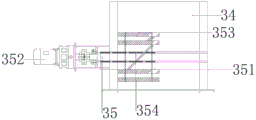
Furthermore, an air inlet A of the quick-drying system is tangentially communicated with the side surface of the horizontal cylinder, a feeding screw rod of the spiral feeder is vertical to the bottom surface of the horizontal cylinder, and the feeding screw rod is positioned above the circle center of the bottom surface of the horizontal cylinder; the central shaft A is connected with the motor through a speed reducer, and stirring blades A are arranged on the central shaft A; the crusher is arranged in the middle of the vertical cylinder and driven by a motor, and the rotating shaft of the motor is perpendicular to the cylinder wall of the vertical cylinder. The crushing machine comprises a crushing cutter set and a motor, the crushing cutter set comprises four crushing blades and a central cutter shaft, the crushing blades are long cubic metal sheets, the central cutter shaft is located on an extension line of the motor rotating shaft and connected with the motor rotating shaft, the crushing blades are parallel to the central cutter shaft and distributed in a pairwise symmetrical mode by taking the crushing blades as a symmetrical shaft, the vertical distance from one pair of crushing blades to the central cutter shaft is d, and the distance from the other pair of crushing blades to the central cutter shaft is smaller than 2 d.
The crusher is arranged to crush the materials with larger particles, when the materials are crushed to a certain particle size, the materials can be conveyed to the cross-flow drying system through air flow, if the particles are still too large, the materials can fall into the horizontal cylinder body, the drying and the stirring are continued, the materials are blown up by the air flow again and are crushed by the crusher for multiple times until the particles enter the cross-flow drying system.
Furthermore, an air inlet B of the flow-through system is tangentially communicated with the side surface of the horizontal cylinder, a central shaft B is connected with the motor through a speed reducer, a stirring blade B is arranged on the central shaft B, and an observation window is arranged on one side of the horizontal cylinder; the barrel bottom is provided with quick sample connection, and quick sample connection is including depositing appearance bucket, butterfly valve and toper appearance mouth, and the butterfly valve setting is on depositing the appearance bucket, and toper appearance mouth setting is under depositing the appearance bucket, and the quick sampling to material in the horizontal drum can be accomplished to the switch of butterfly valve.
The horizontal cylinder is also provided with a spiral air flow guide sheet, the air flow guide sheet can enable air flow entering from the tangential direction to flow along the spiral direction, the action time of the air flow in the cross-flow drying system is prolonged, the heat energy utilization rate is improved, meanwhile, walnut powder is fully stirred to form a fluidized state, and the dry mass and heat transfer efficiency is improved.
Furthermore, a fan A of the induced draft system is connected with a frequency converter, and a temperature sensor, a humidity sensor and an anemoscope are arranged in an air outlet air duct of the fan A.
The fan of the air inducing system can be subjected to frequency conversion, can be adjusted according to the amount of the materials, can control the moisture of the walnut powder at will, and if the moisture content of the walnut powder is higher in the operation process of the equipment, the rotating speed of the fan of the air inducing system is reduced, the staying time of the materials in the drying device is prolonged, and the moisture of the walnut powder is recovered to a normal state; otherwise, the rotation speed is increased. The whole adjusting process can be completed within 5 minutes, so that the moisture content of the final product can be changed, which cannot be realized in a common disc type dryer, if the moisture content is found to be higher or lower in the common dryer, the adjustment can only be performed by changing the feeding speed, the adjusting period is generally 1-2 hours, and the discharged materials are all unqualified products, so that great loss is caused on production.
A temperature sensor, a humidity sensor and an anemoscope are arranged in the air channel, and the frequency of the fan can be adjusted according to real-time feedback parameters.
Furthermore, a cyclone separator B of the cooling system is provided with an interlayer, a circulating cooling medium is arranged in the interlayer, and the bottom of the cyclone separator B is provided with a temperature sensor; the motor of the discharger is connected with a frequency converter.
The dried materials generally have higher temperature, are not suitable for direct packaging and bagging, or cause fire or product quality deterioration due to overheating; the temperature of the materials dried by the disc drying equipment is generally above 90 ℃, and long-time cooling treatment is needed, and after the drying of the disc drying equipment is finished, the temperature of the materials is generally about 35 ℃, the cooling time is short, and the efficiency is high. The temperature sensor at the bottom of the cyclone separator can feed back the temperature condition of the walnut powder in real time, the motor frequency of the discharger is adjusted according to the temperature condition, and the discharging speed is slowed down when the temperature is higher; when the temperature is lower, the discharging speed is accelerated.
Furthermore, a frequency converter, a wind speed sensor, a temperature sensor and a humidity sensor are connected with a programmable controller of the control system.
The invention has the beneficial effects that:
1. the invention belongs to a mobile rapid processing device, raw materials can be provided by consumers, the processing is carried out under the device, finished products are taken away by the consumers on the spot, and the production can be directly finished in the transportation process under the condition of orders in different places, thereby saving the working time and ensuring the freshness of the products;
2. the material can be quickly dried, the moisture content is reduced to below 12% from 65%, only 15 minutes are needed, and the traditional disc type drying equipment needs 1-2 hours;
3. the moisture content of the phosphorus walnut powder can be quickly adjusted, and the frequency conversion of a fan of an induced air system can be adjusted according to the feeding condition in actual production;
4. the drying energy consumption is reduced, the waste heat of the waste gas is recovered, a large amount of waste heat can be recovered from the generator and the waste gas, the drying of the walnut powder is completed, the energy consumption is reduced, and the product cost is reduced;
5. the device is environment-friendly, and the use of the device can reduce the heat discharged to the air by the automobile and reduce the influence on the environment.
Drawings
In order to more clearly illustrate the embodiments of the present invention or the technical solutions in the prior art, the drawings used in the description of the embodiments or the prior art will be briefly described below. It is obvious that the drawings in the following description are some embodiments of the invention, and that for a person skilled in the art, other drawings can be derived from them without inventive effort.
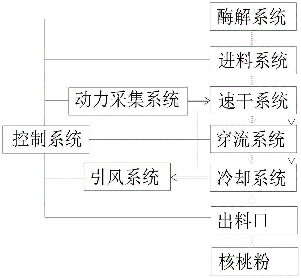
FIG. 1 is a block diagram of the overall structure of the present invention (wherein a single solid line is a control system connection diagram; double solid line arrows are gas flow direction diagrams; double dashed line arrows are material flow direction diagrams);
FIG. 2 is a schematic view of the overall structure of the present invention 1;
FIG. 3 is a schematic view of the overall structure of the present invention 2;
FIG. 4 is a schematic diagram of the enzymatic system of the present invention;
FIG. 5 is a schematic view of the power harvesting system of the present invention;
FIG. 6 is a schematic diagram of the quick drying system of the present invention;
FIG. 7 is a schematic diagram of the flow-through drying system of the present invention;
FIG. 8 is a schematic view of the cooling system configuration of the present invention;
FIG. 9 is a schematic view of the shredder construction of the quick drying system of the present invention;
FIG. 10 is a schematic view of the fast sampling port structure of the present invention;
FIG. 11 is a schematic top view of the air deflector of the present invention;
FIG. 12 is a side view of the air deflector of the present invention;
FIG. 13 is a schematic cross-sectional view of the shredder crushing blade set of the quick drying system of the present invention;
FIG. 14 is a schematic view of the structure of the air induction system of the present invention;
FIG. 15 is a schematic view of the internal structure of the heat exchanger of the present invention;
fig. 16 is a schematic view of the feed system configuration of the present invention.
In the figure, a power collection system 1, a feeding system 2, a quick drying system 3, a flow-through system 4, an induced draft system 5, a cooling system 6, a discharge port 7, an enzymolysis system 8, a heat exchanger 11, an exhaust gas inlet 12, an exhaust gas outlet 13, an air inlet 14, an air outlet 15, a filter screen 16, an air array pipe 17, a condensed water recovery tank 18, a heater 19, a hopper 21, a spiral feeder 22, a stirrer 23, an air inlet A31, a horizontal cylinder 32, a stirring paddle A33, a vertical cylinder 34, a pulverizer 35, an air outlet A36, a central shaft A37, an air inlet B41, a stirring paddle B42, a horizontal cylinder 43, a vertical cylinder 44, an air outlet B45, a central shaft B46, an observation window 47, a quick sampling port 48, an air flow guide sheet 49, a cyclone separator A51, a fan A52, a cyclone separator B61, a fan B62, an interlayer 63, a discharger 71, a crushing knife group 351, a motor, a crushing blade, The device comprises a central knife shaft 354, a sample storage barrel 481, a butterfly valve 482, a conical sample outlet 483, an enzymolysis tank 81, a motor 82, a stirring rod 83, a filter 84, a filter cartridge 85, a screw 86 and a liquid collecting pipe 87.
Detailed Description
In order to make the objects, technical solutions and advantages of the embodiments of the present invention clearer, the technical solutions in the embodiments of the present invention will be clearly and completely described below with reference to the drawings in the embodiments of the present invention. It is to be understood that the embodiments described are only a few embodiments of the present invention, and not all embodiments. All other embodiments, which can be derived by a person skilled in the art from the embodiments given herein without making any creative effort, shall fall within the protection scope of the present invention.
Example 1:
a mobile instant health walnut powder rapid processing device comprises an enzymolysis system 8, a power acquisition system 1, a feeding system 2, a quick drying system 3, a flow-through drying system 4, an induced air system 5, a cooling system 6, a discharge port 7 and a control system;
the enzymolysis system 8 comprises an enzymolysis tank 81 and a filter 84; the top of the enzymolysis tank is provided with a motor 82, the motor is connected with a stirring rod 83 in the tank body, the upper end of the motor is provided with a feeding port, the bottom of the motor is provided with a discharging port, the tank body is internally provided with a heating coil, the heating coil is divided into a plurality of groups and is connected with the motor through a controller; the discharge port is positioned above the feed port of the filter 84 and is connected with the feed port, the filter comprises a feed port, a spiral conveyor and a discharge port, the feed port is arranged above one side of the spiral conveyor, the discharge port is arranged below the other side of the spiral conveyor, the outer wall of the spiral conveyor is a filter cylinder with a hollow interior, a screw 86 is arranged in the filter cylinder, and the screw is connected with a speed reducer and a motor through a bearing; a liquid collecting pipe 87 is arranged outside the filter cylinder and is connected with a waste liquid tank;
the power acquisition system 1 comprises a power system and a waste heat acquisition system, the power system is connected with an automobile power supply and/or a storage battery, the heater 19 is controlled to heat, a heating pipe is arranged on the inner wall of the heater, one end of the heater is a cold air inlet, the other end of the heater is a hot air outlet, and the hot air outlet is communicated with the quick drying system 3; the waste heat collecting system comprises a heat exchanger 11, a waste gas inlet 12, a waste gas outlet 13, an air inlet 14 and an air outlet 15; the bottom of the heat exchanger 11 is communicated with a waste gas inlet 12, one side of the upper part of the heat exchanger is communicated with a waste gas outlet 13, an air inlet 14 is connected to one side of the heat exchanger 11, and the top of the heat exchanger 11 is communicated with an air outlet 15; the heat exchanger is also provided with a combustion furnace which is connected with a fuel storage tank; the automobile power supply and/or the large-capacity storage battery provide electric energy for the electric equipment on one hand and provide heat energy required by drying on the other hand; the waste heat collecting system can be communicated with an automobile tail gas pipe to recover partial heat energy, and the waste gas flowing cavity of the heat exchanger can exchange heat through the fuel combustion furnace under the condition of insufficient heat energy to heat air to finish drying; the heated air directly enters the drying cavity through the quick drying system;
the feeding system 2 comprises a hopper 21, a screw feeder 22 and a stirrer 23; the stirrer 23 is arranged in the middle of the inside of the hopper 21, and the spiral feeder is arranged at the bottom of the inside of the hopper 21 and communicated with the hopper 21; the screw feeder 22 and the stirrer 23 are connected with a motor through a transmission device; the quick drying system 3 comprises an air inlet A31, a horizontal cylinder 32, a stirring paddle A33, a vertical cylinder 34, a pulverizer 35 and an air outlet A36; the air inlet A31 is connected above the front end of the horizontal cylinder 32, the horizontal cylinder 32 is provided with a central shaft A37, the central shaft A37 is driven by a motor, and the central shaft A37 is provided with a stirring blade A33; the upper part of the rear end of the horizontal cylinder 32 is connected with the vertical cylinder 34, the middle part of the vertical cylinder 34 is provided with a crusher 35, the top is closed, the side wall of the top is provided with an air outlet A36 which is connected with an air inlet B41 of the flow-through system 4;
the flow-through system 4 comprises an air inlet B41, a stirring paddle B42, a horizontal cylinder 43, a vertical cylinder 44 and an air outlet B45; the horizontal cylinder 43 is provided with a central shaft B46, the central shaft B46 is driven by a motor, the central shaft B46 is provided with a stirring paddle B42, the bottom surfaces of two ends of the horizontal cylinder 43 are closed, and two vertical cylinders 44 are vertically arranged on the side surfaces of two ends of the cylinder and are respectively connected with the pre-drying system 3 and the induced draft system 5; the air inlet B41 is arranged on the vertical cylinder 44 connected with the pre-drying system 3, and the air outlet B45 is arranged on the vertical cylinder 44 connected with the induced air system 5;
an airflow guide sheet 49 is arranged in the horizontal cylinder of the flow passing system 4, the airflow guide sheet 49 can change the flow direction of airflow and flow along a spiral line type mode, and the airflow guide sheet 49 is an annular guide blade;
the induced draft system 5 comprises a cyclone separator A51, a fan A52 and an air duct; the upper end of the cyclone separator A51 is connected with a fan A52 through an air duct, and the other side of the upper end of the cyclone separator A51 is connected with an air outlet B45 of the flow-through system 4;
the cooling system 6 comprises a cyclone separator B61, a fan B62 and an air duct; the upper end of the cyclone separator B61 is connected with a fan B62 through an air duct, and the other side of the upper end is connected with the lower end of a cyclone separator A51 of the induced draft system 5;
the heat exchanger 11 of the waste heat collecting system is a separated tube type heat exchanger, and the heat exchanger 11 is respectively connected with a waste gas inlet and a waste gas outlet and an air inlet and outlet to realize the exchange of waste gas heat and air heat; the feeding system 2 is connected with the quick-drying system 3, the spiral feeder 22 is communicated with a horizontal cylinder 32 of the quick-drying system 3, an air outlet 15 connected with the heat exchanger 11 is communicated with an air inlet A31 through an air duct, the air inlet A31 is arranged on the horizontal cylinder 32, and the vertical cylinder 34 is arranged at one end of the horizontal cylinder 32 far away from the feeding system 2; the pre-drying system 3 and the induced draft system 5 are respectively connected with a feed end vertical cylinder 44 and a discharge end vertical cylinder 44 of the flow-through system 4;
the induced draft system 5 is communicated with the flow passing system 4 through an air duct, the air duct is connected with a cyclone separator A51, and the tail end of the air duct is connected with a fan A52; an air duct of the cooling system 6 is arranged below the cyclone separator A51 and is connected with the upper end of the cyclone separator B61, the air duct of the cooling system 6 is connected with the cyclone separator B61 and the fan B62 of the cooling system 6, a discharge port 7 is arranged below the cyclone separator 62 of the cooling system 6, and a discharger 71 is arranged at the discharge port 7;
the enzymolysis system 8, the power acquisition system 1, the feeding system 2, the quick drying system 3, the flow-through system 4, the induced air system 5, the cooling system 6 and the motor, the sensor and other electrical appliances on the discharge hole 7 are all connected with a control system, and the control system is a multi-channel programmable controller;
the air tube 17 of the heat exchanger 11, the quick drying system 3, the flow penetrating system 4 and the induced draft system 5 are communicated through an air duct to form an air flow channel.
The air inlet 14 of the waste heat collecting system is provided with a filter screen 16, an air tube 17 of the heat exchanger 11 and a horizontal plane form a 15-degree angle, the bottom of one side of the heat exchanger 11 comprises a condensate water recovery tank 18, a waste gas outlet 13 of the heat exchanger 11 is connected with a fan through an air duct, and an air outlet end of the fan is connected with a flue.
An air inlet A31 of the quick-drying system 3 is tangentially communicated with the side surface of the horizontal cylinder 32, a feeding screw of the screw feeder 22 is vertical to the bottom surface of the horizontal cylinder 32, and the feeding screw is positioned above the circle center of the bottom surface of the horizontal cylinder 32; the central shaft A37 is connected with the motor through a speed reducer, and a stirring paddle A33 is arranged on the central shaft A37; the crusher 35 is arranged in the middle of the vertical cylinder 34, the crusher 35 is driven by a motor, and the rotating shaft of the motor is perpendicular to the cylinder wall of the vertical cylinder 34. The crusher 35 comprises a crushing cutter group 351 and a motor 352, the crushing cutter group 351 comprises four crushing blades 353 and a central cutter shaft 354, the crushing blades 353 are long cubic metal sheets, the central cutter shaft 354 is positioned on an extension line of a rotating shaft of the motor 352 and is connected with the rotating shaft of the motor 352, the crushing blades 353 are parallel to the central cutter shaft 354 and are symmetrically distributed pairwise by taking the central cutter shaft 354 as a symmetric shaft, the vertical distance from one pair of the crushing blades 353 to the central cutter shaft 354 is d, and the distance from the other pair of the crushing blades 353 to the central cutter shaft 354 is less than 2 d.
An air inlet B41 of the flow-through system 4 is tangentially communicated with the side surface of the horizontal cylinder 43, a central shaft B46 is connected with a motor through a speed reducer, a stirring blade B42 is arranged on the central shaft B46, and an observation window 47 is arranged on one side of the horizontal cylinder 43; the barrel bottom is provided with quick sample connection 48, and quick sample connection includes sample storage bucket 481, butterfly valve 482 and toper appearance port 483, and butterfly valve 482 sets up on sample storage bucket 481, and toper appearance port 483 sets up under sample storage bucket 481, and the quick sample of material in horizontal drum 43 can be accomplished to the switch of butterfly valve 482.
A fan A52 of the induced draft system 5 is connected with a frequency converter, and a temperature sensor, a humidity sensor and an anemoscope are arranged in an air outlet air duct of the fan A52.
The cyclone separator B61 of the cooling system 6 is provided with an interlayer 63, a circulating cooling medium is arranged in the interlayer 63, and the bottom of the cyclone separator B61 is provided with a temperature sensor; the motor of the discharger 71 is connected with a frequency converter.
And a programmable controller of the control system is connected with a frequency converter, an air speed sensor, a temperature sensor and a humidity sensor.
Example 2:
the outer edge of the propeller blade of the screw is coated with a cleaning brush. It can be self-cleaning in case of filter cartridge filter holes clogging.
The rest of the structure is the same as that of embodiment 1.
The walnut kernel raw material is dried by the equipment and the traditional powder making equipment (soaking, grinding, slurry-residue separation (removing bitter brown skin), deodorization, batching, homogenization, concentration sterilization and spray drying production line), and the effects are compared as follows:
the equipment can provide high-quality walnut powder, particularly reduce the damage of vitamins, fats (unsaturated fatty acids) and other active ingredients sensitive to high temperature, high heat and high humidity, has rich nutrient component types and high content, can provide raw materials by consumers, is processed under the device, takes off finished products by the consumers on the spot, and has wide market prospect.