CN107389272B - SO (SO) 3 Standard gas generating device and calibration method - Google Patents
SO (SO) 3 Standard gas generating device and calibration method Download PDFInfo
- Publication number
- CN107389272B CN107389272B CN201710674122.2A CN201710674122A CN107389272B CN 107389272 B CN107389272 B CN 107389272B CN 201710674122 A CN201710674122 A CN 201710674122A CN 107389272 B CN107389272 B CN 107389272B
- Authority
- CN
- China
- Prior art keywords
- gas
- pipeline
- pressure
- standard
- deionized water
- Prior art date
- Legal status (The legal status is an assumption and is not a legal conclusion. Google has not performed a legal analysis and makes no representation as to the accuracy of the status listed.)
- Active
Links
Images

Classifications
-
- G—PHYSICS
- G01—MEASURING; TESTING
- G01M—TESTING STATIC OR DYNAMIC BALANCE OF MACHINES OR STRUCTURES; TESTING OF STRUCTURES OR APPARATUS, NOT OTHERWISE PROVIDED FOR
- G01M3/00—Investigating fluid-tightness of structures
- G01M3/02—Investigating fluid-tightness of structures by using fluid or vacuum
-
- G—PHYSICS
- G01—MEASURING; TESTING
- G01F—MEASURING VOLUME, VOLUME FLOW, MASS FLOW OR LIQUID LEVEL; METERING BY VOLUME
- G01F25/00—Testing or calibration of apparatus for measuring volume, volume flow or liquid level or for metering by volume
-
- G—PHYSICS
- G01—MEASURING; TESTING
- G01N—INVESTIGATING OR ANALYSING MATERIALS BY DETERMINING THEIR CHEMICAL OR PHYSICAL PROPERTIES
- G01N33/00—Investigating or analysing materials by specific methods not covered by groups G01N1/00 - G01N31/00
- G01N33/0004—Gaseous mixtures, e.g. polluted air
- G01N33/0009—General constructional details of gas analysers, e.g. portable test equipment
- G01N33/0027—General constructional details of gas analysers, e.g. portable test equipment concerning the detector
- G01N33/0036—General constructional details of gas analysers, e.g. portable test equipment concerning the detector specially adapted to detect a particular component
- G01N33/0042—SO2 or SO3
-
- Y—GENERAL TAGGING OF NEW TECHNOLOGICAL DEVELOPMENTS; GENERAL TAGGING OF CROSS-SECTIONAL TECHNOLOGIES SPANNING OVER SEVERAL SECTIONS OF THE IPC; TECHNICAL SUBJECTS COVERED BY FORMER USPC CROSS-REFERENCE ART COLLECTIONS [XRACs] AND DIGESTS
- Y02—TECHNOLOGIES OR APPLICATIONS FOR MITIGATION OR ADAPTATION AGAINST CLIMATE CHANGE
- Y02A—TECHNOLOGIES FOR ADAPTATION TO CLIMATE CHANGE
- Y02A50/00—TECHNOLOGIES FOR ADAPTATION TO CLIMATE CHANGE in human health protection, e.g. against extreme weather
- Y02A50/20—Air quality improvement or preservation, e.g. vehicle emission control or emission reduction by using catalytic converters
Landscapes
- Physics & Mathematics (AREA)
- General Physics & Mathematics (AREA)
- Fluid Mechanics (AREA)
- Sampling And Sample Adjustment (AREA)
- Feeding, Discharge, Calcimining, Fusing, And Gas-Generation Devices (AREA)
Abstract
本发明公开了一种SO3标准气体发生装置及标定方法,发生装置包括气体发生系统和装置标定系统;气体发生系统包括SO2/N2高压混合气体管道、O2高压气体管道、N2高压气体管道、气体混合管道、去离子水管道、盘管式气体混合加热器、含有钒触媒的反应器、排气管道和SO3标准气体采集管道;各气体管道分别设有减压阀和气体质量流量计,去离子水管道设有平流泵;装置标定系统包括分别设于各气体质量流量计前后与气体管道连通的校准管道;各气体管道上于气体质量流量计后的校准管道、气体混合管道之间分别设有球阀;各校准管道分别设有球阀;去离子水管道设有球阀,球阀前的管道连通有排水管道,排水管道上设有球阀;排气管道和SO3标准气体采集管道设有球阀。
The invention discloses a SO 3 standard gas generating device and a calibration method. The generating device includes a gas generating system and a device calibration system; the gas generating system includes a SO 2 /N 2 high-pressure mixed gas pipeline, an O 2 high-pressure gas pipeline, and a N 2 high-pressure gas pipeline. Gas pipeline, gas mixing pipeline, deionized water pipeline, coiled gas mixing heater, reactor containing vanadium catalyst, exhaust pipeline and SO 3 standard gas collection pipeline; each gas pipeline is equipped with a pressure reducing valve and gas quality The flow meter and the deionized water pipeline are equipped with an advection pump; the calibration system of the device includes calibration pipelines connected with the gas pipelines respectively located before and after each gas mass flowmeter; calibration pipelines and gas mixing pipelines on each gas pipeline behind the gas mass flowmeter There are ball valves between them; each calibration pipeline is equipped with a ball valve; the deionized water pipeline is equipped with a ball valve, the pipeline in front of the ball valve is connected with a drainage pipeline, and a ball valve is installed on the drainage pipeline; the exhaust pipeline and the SO 3 standard gas collection pipeline are set There are ball valves.
Description
技术领域technical field
本发明属于环境工程领域,涉及一种SO3标准气体发生装置及标定方法。The invention belongs to the field of environmental engineering and relates to an SO3 standard gas generating device and a calibration method.
背景技术Background technique
SO3作为存在于燃煤烟气中一种特殊污染物,其具有危害高,难控制,难检测的特点。近年来随着我国对燃煤大气污染控制的日益关注和研究的不断深入,对SO3污染的关注度也逐步提升,众多大气污染问题,诸如雾霾、电厂蓝烟、电厂烟道及相关设备腐蚀等均发现与SO3有着密切的联系。但由于对SO3排放问题的重视程度不够,在SO3排放控制、检测方面缺乏合理有效的手段。虽然能够参考美国环境保护局提供的EPA-8a方法以及电力行业标准《石灰石-石膏湿法烟气脱硫装置性能验收试验规范》(DL/T 998-2016)中所描述的测定方法对烟气中SO3进行采样检测,但作为一种定量测试方法,必须具备相应的标准物质对方法本身的测量精确度进行检验。目前国内在SO3标准气体产品和SO3标准气体发生装置方面尚处于空白,因而难以提供准确、权威的烟气中SO3浓度检测结果。As a special pollutant existing in coal-fired flue gas, SO 3 has the characteristics of high hazard, difficult control and detection. In recent years, with China's increasing attention to the control of coal-fired air pollution and the deepening of research, the attention to SO 3 pollution has also gradually increased. Many air pollution problems, such as smog, blue smoke from power plants, power plant flues and related equipment Corrosion, etc. are found to have a close relationship with SO 3 . However, due to insufficient attention to the issue of SO 3 emissions, there is a lack of reasonable and effective means in the control and detection of SO 3 emissions. Although it is possible to refer to the EPA-8a method provided by the US Environmental Protection Agency and the determination method described in the power industry standard "Limestone-Gypsum Wet Flue Gas Desulfurization Unit Performance Acceptance Test Specification" (DL/T 998-2016) SO 3 is sampled and tested, but as a quantitative test method, corresponding reference materials must be available to test the measurement accuracy of the method itself. At present, there is still a gap in SO 3 standard gas products and SO 3 standard gas generating devices in China, so it is difficult to provide accurate and authoritative detection results of SO 3 concentration in flue gas.
发明内容Contents of the invention
本发明的目的在于克服现有技术的不足,提供一种SO3标准气体发生装置及标定方法,用于生成含量准确的SO3混合气,并能对装置本身的准确性进行标定和验证,从而用于对现有气态SO3测定装置和方法提供校准和鉴定。The purpose of the present invention is to overcome the deficiencies in the prior art, provide a kind of SO Standard gas generating device and calibration method, be used for generating the SO of accurate content Mixed gas, and the accuracy of device itself can be calibrated and verified, thereby It is used to provide calibration and qualification for existing gaseous SO 3 determination devices and methods.
上述目的是通过如下技术方案实现的:The above-mentioned purpose is achieved through the following technical solutions:
一种SO3标准气体发生装置,包括气体发生系统和装置标定系统:A kind of SO Standard gas generating device, including gas generating system and device calibration system:
气体发生系统:包括SO2/N2高压混合气体管道、O2高压气体管道、N2高压气体管道、气体混合管道、去离子水管道、盘管式气体混合加热器、含有钒触媒的反应器、排气管道和SO3标准气体采集管道;SO2/N2高压混合气体管道、O2高压气体管道、N2高压气体管道分别与气体混合管道连通,气体混合管道和去离子水管道分别与盘管式气体混合加热器的入口连通,盘管式气体混合加热器的出口与反应器的入口连通,排气管道和SO3标准气体采集管道与反应器的出口连通;所述SO2/N2高压混合气体管道、O2高压气体管道、N2高压气体管道分别设有减压阀和气体质量流量计,去离子水管道设有平流泵;Gas generation system: including SO 2 /N 2 high pressure mixed gas pipeline, O 2 high pressure gas pipeline, N 2 high pressure gas pipeline, gas mixing pipeline, deionized water pipeline, coil gas mixing heater, reactor containing vanadium catalyst , exhaust pipeline and SO 3 standard gas collection pipeline; SO 2 /N 2 high-pressure mixed gas pipeline, O 2 high-pressure gas pipeline, N 2 high-pressure gas pipeline are respectively connected with the gas mixing pipeline, and the gas mixing pipeline and deionized water pipeline are respectively connected with the The inlet of the coiled gas mixing heater is connected, the outlet of the coiled gas mixing heater is connected with the inlet of the reactor, and the exhaust pipe and the SO standard gas collection pipe are connected with the outlet of the reactor; the SO 2 /N 2 The high-pressure mixed gas pipeline, the O2 high-pressure gas pipeline, and the N2 high-pressure gas pipeline are respectively equipped with a pressure reducing valve and a gas mass flow meter, and the deionized water pipeline is equipped with an advection pump;
装置标定系统:包括分别设于各气体质量流量计前后与气体管道连通的校准管道;Device calibration system: including calibration pipes connected to the gas pipelines respectively located at the front and rear of each gas mass flow meter;
SO2/N2高压混合气体管道、O2高压气体管道、N2高压气体管道上于气体质量流量计后的校准管道、气体混合管道之间分别设有球阀;各校准管道分别设有球阀;去离子水管道设有球阀,该球阀前的管道还连通有排水管道,排水管道上设有球阀;排气管道和SO3标准气体采集管道分别设有球阀。The SO 2 /N 2 high-pressure mixed gas pipeline, the O 2 high-pressure gas pipeline, and the N 2 high-pressure gas pipeline are respectively equipped with ball valves between the calibration pipeline behind the gas mass flowmeter and the gas mixing pipeline; each calibration pipeline is respectively equipped with a ball valve; The deionized water pipeline is provided with a ball valve, and the pipeline in front of the ball valve is also connected with a drainage pipeline, and a ball valve is provided on the drainage pipeline; the exhaust pipeline and the SO 3 standard gas collection pipeline are respectively provided with ball valves.
优选地,所述盘管式气体混合加热器的出口还设有中部采样管道,该管道设有球阀。Preferably, the outlet of the coil-type gas mixing heater is also provided with a central sampling pipe, and the pipe is provided with a ball valve.
优选地,所述去离子水管道上于球阀、盘管式气体混合加热器入口之间设有测压点。Preferably, the deionized water pipeline is provided with a pressure measuring point between the ball valve and the inlet of the coil gas mixing heater.
优选地,盘管式气体混合加热器的出口、反应器的入口处分别设有测温点。Preferably, the outlet of the coiled gas mixing heater and the inlet of the reactor are respectively provided with temperature measuring points.
利用上述发生装置制备SO3标准气体的方法,包括如下流程:Utilize above-mentioned generator to prepare SO The method for standard gas comprises the following processes:
(1)以SO2/N2高压混合气体、O2高压气体、N2高压气体作为气源,三路气体经减压阀调压后分别经由气体质量流量计控制流量后汇入气体混合管道,再进入盘管式气体混合加热器,使得各气体组分充分混合并加热至反应温度;(1) With SO 2 /N 2 high-pressure mixed gas, O 2 high-pressure gas, and N 2 high-pressure gas as the gas source, the three-way gas is adjusted by a pressure reducing valve and then flows into the gas mixing pipeline after being controlled by a gas mass flow meter , and then enter the coiled gas mixing heater, so that the gas components are fully mixed and heated to the reaction temperature;
(2)去离子水经平流泵准确计量后,注入盘管式气体混合加热器受热汽化,并与其它气体形成混合气体;(2) After the deionized water is accurately metered by the advection pump, it is injected into the coil type gas mixing heater to be heated and vaporized, and forms a mixed gas with other gases;
(3)混合气体由盘管式气体混合加热器进入反应器,与钒触媒接触并发生催化反应,混合气体中SO2被完全氧化生成SO3;(3) The mixed gas enters the reactor by the coil type gas mixing heater, contacts with the vanadium catalyst and undergoes a catalytic reaction, and SO in the mixed gas is completely oxidized to generate SO 3 ;
(4)由反应器后的SO3标准气体采集管道导出的气体中SO3含量已知且稳定,可作为SO3标准气体,其中SO3浓度C(μL/L)按照下式进行计算:(4) SO content is known and stable in the gas exported by the SO standard gas collection pipeline behind the reactor, which can be used as SO standard gas, wherein the SO concentration C (μL/L) is calculated according to the following formula:

式中,C1为SO2/N2高压混合气体中的SO2浓度(μL/L);In the formula, C 1 is the SO 2 concentration (μL/L) in the SO 2 /N 2 high-pressure mixed gas;
Q1为SO2/N2高压混合气体供气速率(L/min,标准状态);Q 1 is the gas supply rate of SO 2 /N 2 high-pressure mixed gas (L/min, standard state);
Q2为O2高压气体供气速率(L/min,标准状态);Q 2 is O 2 high-pressure gas supply rate (L/min, standard state);
Q3为N2高压气体供气速率(L/min,标准状态);Q 3 is N 2 high-pressure gas supply rate (L/min, standard state);
Q4为去离子水注入速率(g/min);Q 4 is deionized water injection rate (g/min);
(5)剩余尾气由反应器后的排气管道排出,并经由盛有碱性吸收液的莫氏吸收瓶脱除其中酸性气体后排空。(5) The remaining tail gas is discharged from the exhaust pipe behind the reactor, and the acid gas is removed through the Mohs absorption bottle filled with alkaline absorption liquid and then emptied.
上述发生装置的标定方法,包括如下流程:The calibration method of the above-mentioned generating device includes the following procedures:
(1)气密性检查:(1) Air tightness check:
参照《石油化工有毒可燃介质钢制管道工程施工及验收规范》(SH 3501-2011)中管道系统压力试验及泄露性试验部分的要求,对发生装置的气密性进行检查;Check the air tightness of the generating device with reference to the requirements of the pressure test and leakage test of the pipeline system in the "Petrochemical Toxic and Flammable Medium Steel Pipeline Engineering Construction and Acceptance Code" (SH 3501-2011);
(2)气体质量流量计校准:(2) Gas mass flowmeter calibration:
参照《皂膜流量计检定规程》(JJG 586-2006),对发生装置中所包含的三台气体质量流量计进行校准;Refer to the "Soap Film Flowmeter Verification Regulations" (JJG 586-2006) to calibrate the three gas mass flowmeters included in the generator;
(3)平流泵加水速率校准:(3) Calibration of the water filling rate of the advection pump:
利用合适容器盛装一定质量的去离子水作为平流泵供水源,校准前先利用精密天平称量容器中去离子水的质量,再开启平流泵,调节泵出速率至某一稳定值后,由容器中抽取去离子水,同时利用秒表计时,待抽取指定时长后将平流泵关闭,并再次称量容器中去离子水的质量,通过计算去离子水质量变化与抽取时间的比值,以此获得平流泵的实际泵出速率;按照相同流程设置一系列泵出速率测试点,则获得平流泵控制泵出速率与实际泵出速率的关系曲线,以此对所述发生装置中包含的平流泵校准;Use a suitable container to hold a certain quality of deionized water as the water supply source for the advection pump. Before calibration, use a precision balance to weigh the quality of the deionized water in the container, then turn on the advection pump, and adjust the pumping rate to a certain stable value. Extract deionized water in the container, and use a stopwatch to time the time. After the specified time of extraction, turn off the advection pump, and weigh the quality of the deionized water in the container again. By calculating the ratio of the change in the quality of deionized water to the extraction time, the advection pump can be obtained. The actual pumping rate of the pump; a series of pumping rate test points are set according to the same process, then the relationship curve between the controlled pumping rate of the advection pump and the actual pumping rate is obtained, so as to calibrate the advection pump included in the generating device;
(4)SO2/N2高压混合气体中SO2浓度校验:(4) SO 2 concentration verification in SO 2 /N 2 high-pressure mixed gas:
4.1准备两只莫式吸收瓶,向其中分别注入一定量的10%浓度H2O2吸收液,再将其串联,并连接至SO2/N2高压混合气体管道上气体质量流量计之后的校准管道;4.1 Prepare two Moss absorption bottles, inject a certain amount of 10% H2O2 absorption liquid into them respectively, connect them in series, and connect them to the gas mass flowmeter on the SO2 / N2 high-pressure mixed gas pipeline. calibration pipes;
4.2将SO2/N2高压混合气体利用气体减压阀调压后向气体质量流量计供气,调节供气速率至指定值,待供气稳定后,将气路切换至气体质量流量计之后的校准管道,同时利用秒表开始计时;4.2 Regulate the pressure of the SO 2 /N 2 high-pressure mixed gas with the gas pressure reducing valve to supply gas to the gas mass flowmeter, adjust the gas supply rate to the specified value, and after the gas supply is stable, switch the gas path to the gas mass flowmeter Calibrate the pipeline, and start timing with a stopwatch at the same time;
4.3被校验气体流经串联布置的两只莫式吸收瓶,其中的SO2成分被吸收;待通气指定时长后,将该校准管道上的球阀关闭,并关闭SO2/N2高压混合气体供气;4.3 The gas to be calibrated flows through two Moss absorption bottles arranged in series, and the SO 2 component in it is absorbed; after a specified period of ventilation, the ball valve on the calibration pipeline is closed, and the SO 2 /N 2 high-pressure mixed gas is closed air supply;
4.4将两只莫式吸收瓶中的吸收液分别取出,参照《工业循环冷却水及锅炉水中氟、氯、磷酸根、亚硝酸根、硝酸根和硫酸根的测定离子色谱法》(GB/T 14642-2009)或《石灰石-石膏湿法烟气脱硫装置性能验收试验规范》(DL/T 998-2016)对其中的硫酸根含量进行测定;若后方莫式吸收瓶中的吸收液内未检出含有硫酸根,或硫酸根含量低于某一限值,则表明SO2/N2高压混合气体中的SO2已被完全捕集;4.4 Take out the absorption liquid in the two Mohs absorption bottles respectively, and refer to "Ion Chromatography for the Determination of Fluorine, Chlorine, Phosphate, Nitrite, Nitrate and Sulfate in Industrial Circulating Cooling Water and Boiler Water" (GB/T 14642-2009) or "Limestone-Gypsum Wet Flue Gas Desulfurization Equipment Performance Acceptance Test Specification" (DL/T 998-2016) to determine the sulfate content; If it contains sulfate, or the sulfate content is lower than a certain limit, it indicates that SO 2 in the SO 2 /N 2 high-pressure mixed gas has been completely captured;
4.5测定得到前方莫式吸收瓶中的吸收液内所含硫酸根总量,再根据通气时长和SO2/N2高压混合气体供气速率,按下式计算得到SO2/N2高压混合气体中SO2的准确浓度C1(μL/L):4.5 Measure the total amount of sulfate radical contained in the absorption liquid in the front Mohs absorption bottle, and then calculate the SO 2 /N 2 high-pressure mixed gas according to the following formula according to the ventilation time and the SO 2 /N 2 high-pressure mixed gas supply rate The exact concentration of SO 2 in C 1 (μL/L):

式中,MS为前方莫式吸收瓶中的吸收液内所含有的硫酸根总量(mg);In the formula, MS is the sulfate radical total amount (mg) contained in the absorption liquid in the front Mohs absorption bottle;
Q1'为SO2/N2高压混合气体供气速率(L/min,标准状态);Q 1' is the gas supply rate of SO 2 /N 2 high-pressure mixed gas (L/min, standard state);
T为通气时长T(s);T is the ventilation time T(s);
(5)SO3标准气体发生装置出口气体中SO3浓度校验:(5) Verification of the concentration of SO 3 in the outlet gas of the SO 3 standard gas generator:
5.1准备三只莫式吸收瓶,向前两只莫式吸收瓶中分别注入一定量的10%浓度的异丙醇吸收液,并且通过水浴方式调节前两只莫式吸收瓶及其中吸收液温度至某一恒定值;向第三只莫式吸收瓶中注入一定量的10%浓度H2O2吸收液,将这三只莫式吸收瓶依次串联,并连接至反应器之后的SO3标准气体采集管道;5.1 Prepare three Moss absorption bottles, inject a certain amount of 10% isopropanol absorption liquid into the first two Moss absorption bottles, and adjust the temperature of the first two Moss absorption bottles and the absorption liquid in the water bath to a constant value; inject a certain amount of 10% concentration H 2 O 2 absorption liquid into the third Mohs absorption bottle, connect the three Mohs absorption bottles in series, and connect to the SO 3 standard behind the reactor Gas collection pipeline;
5.2开启盘管式气体混合加热器和反应器,分别控制加热温度至指定值,将SO2/N2高压混合气体、O2高压气体、N2高压气体分别利用气体减压阀调压后向对应的气体质量流量计供气,调节供气速率至指定值;开启平流泵,调节注水速率至指定值,向盘管式气体混合加热器中注入去离子水;待温度、供气和供水稳定后,将气路切换至反应器之后的SO3标准气体采集管道,同时利用秒表开始计时;5.2 Turn on the coil-type gas mixing heater and reactor, control the heating temperature to the specified value respectively, and adjust the pressure of SO 2 /N 2 high-pressure mixed gas, O 2 high-pressure gas, and N 2 high-pressure gas respectively to the The corresponding gas mass flowmeter supplies gas, adjust the gas supply rate to the specified value; turn on the advection pump, adjust the water injection rate to the specified value, and inject deionized water into the coil gas mixed heater; wait for the temperature, gas supply and water supply to stabilize Finally, switch the gas path to the SO standard gas collection pipeline behind the reactor, and start timing with a stopwatch;
5.3被校验气体流经串联布置的三只莫式吸收瓶,其中存在的SO2和SO3成分被吸收;待通气指定时长后,将SO3标准气体采集管道上的球阀关闭,并关闭SO2/N2高压混合气体、O2高压气体、N2高压气体供气;5.3 The gas to be calibrated flows through three Morse absorption bottles arranged in series, and the SO 2 and SO 3 components present in them are absorbed; after a specified period of ventilation, the ball valve on the SO 3 standard gas collection pipeline is closed, and the SO 3 is closed. 2 /N 2 high pressure mixed gas, O 2 high pressure gas, N 2 high pressure gas supply;
5.4将三只莫式吸收瓶中的吸收液分别取出,参照GB/T 14642-2009或DL/T 998-2016,对其中的硫酸根含量进行测定;若同时满足以下条件,则表明SO2/N2高压混合气体中SO2被完全氧化为SO3,且所发生的SO3标准气体中的SO3浓度与上述计算得到的SO3浓度相一致:5.4 Take out the absorption liquid in the three Mohsel absorption bottles respectively, and measure the sulfate content in them with reference to GB/T 14642-2009 or DL/T 998-2016; if the following conditions are met at the same time, it means that SO 2 / SO 2 in the N 2 high - pressure mixed gas is completely oxidized to SO 3 , and the resulting SO 3 concentration in the standard gas is consistent with the SO 3 concentration calculated above:
A、中间莫式吸收瓶中的吸收液未检出含有硫酸根,或硫酸根含量低于某一限值;A. The absorption liquid in the middle Mohs absorption bottle does not contain sulfate radicals, or the sulfate radical content is lower than a certain limit;
B、最后莫式吸收瓶中的吸收液未检出含有硫酸根,或硫酸根含量低于某一限值。B. The absorption solution in the last Mohs absorption bottle contains no sulfate radicals, or the sulfate radical content is lower than a certain limit.
本发明的有益效果:Beneficial effects of the present invention:
1、本发明提供的SO3标准气体发生装置结构简洁,运行稳定性好,可靠性高,可产生浓度准确的SO3标准气体,能够满足标准《气体分析标定用混合气体的制备》(ISO 6142-2001)对标准气体质量的要求,可供各种类型的气态SO3测定装置和方法进行校准和鉴定。1, the SO provided by the present invention Standard gas generating device is simple in structure, good in operation stability, high in reliability, can produce SO with accurate concentration standard gas, and can meet the standard "Preparation of Mixed Gas for Gas Analysis and Calibration" (ISO 6142 -2001) requirements for standard gas quality, which can be used for calibration and identification of various types of gaseous SO 3 measuring devices and methods.
2、本发明提供的SO3标准气体发生装置,其发生气量和气态SO3浓度可根据实际需求进行调节,适用范围广,灵活性高。2. The SO 3 standard gas generator provided by the present invention can generate gas volume and gaseous SO 3 concentration that can be adjusted according to actual needs, and has a wide application range and high flexibility.
3、基于燃煤烟气中所含水分对于SO3采样过程有显著影响这一特征,本发明提供的SO3标准气体发生装置包含了气体水分调节这一功能,更符合实际应用的要求。3. Based on the fact that the moisture contained in coal-fired flue gas has a significant impact on the SO 3 sampling process, the SO 3 standard gas generator provided by the present invention includes the function of gas moisture adjustment, which is more in line with the requirements of practical applications.
4、本发明中有针对性的提出了一整套逻辑严密的自标定方法,在本发明提供的SO3标准气体发生装置实际使用之前,可通过一系列的校验流程,确保所产生的SO3标准气体中SO3浓度是准确且稳定的,以满足方法自身的严谨性和可靠性。4. In the present invention, a whole set of self-calibration method with rigorous logic is put forward. Before the SO 3 standard gas generating device provided by the present invention is actually used, a series of calibration procedures can be performed to ensure that the generated SO 3 The SO3 concentration in the standard gas is accurate and stable to meet the rigor and reliability of the method itself.
附图说明Description of drawings
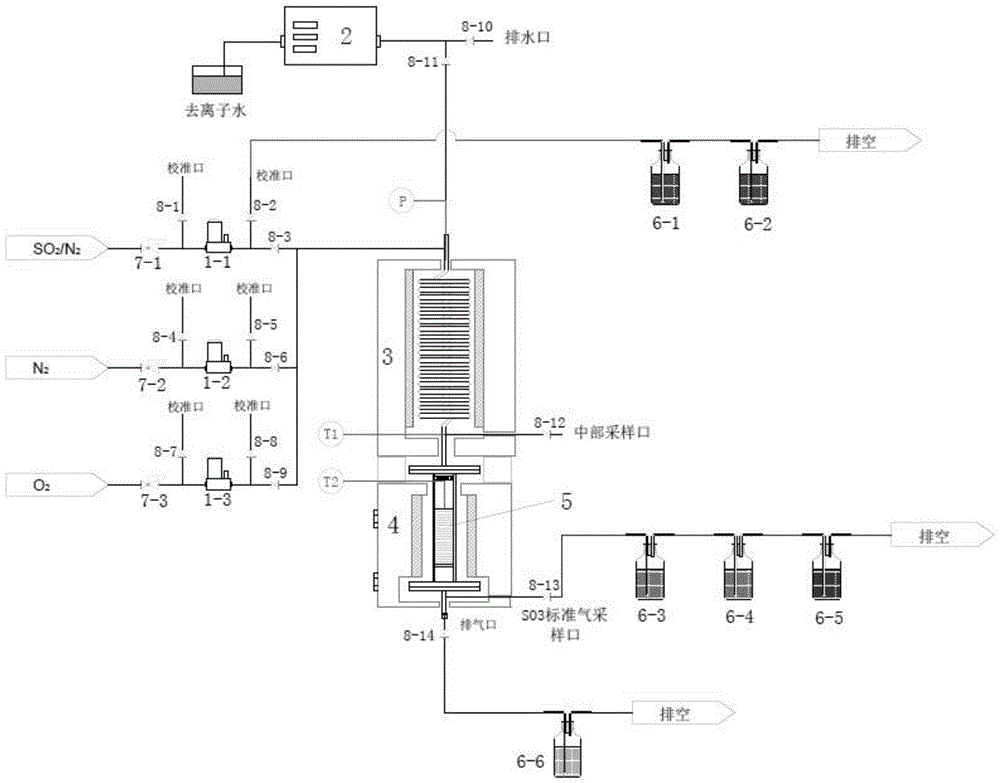
图1为本发明SO3标准气体发生装置的结构示意图;Fig. 1 is SO of the present invention The structural representation of standard gas generator;
图中,1-1~1-3—气体质量流量计,2—平流泵,3—盘管式气体混合加热器,4—反应器,5—钒触媒,6-1~6-6—莫式吸收瓶,7-1~7-3—气体减压阀,8-1~8-14—球阀,P—测压点,T-1、T-2—测温点。In the figure, 1-1~1-3—gas mass flowmeter, 2—advection pump, 3—coil gas mixing heater, 4—reactor, 5—vanadium catalyst, 6-1~6-6—Mo Type absorption bottle, 7-1~7-3—gas pressure reducing valve, 8-1~8-14—ball valve, P—pressure measuring point, T-1, T-2—temperature measuring point.
具体实施方式Detailed ways
下面结合附图具体介绍本发明的技术方案。The technical solution of the present invention will be described in detail below in conjunction with the accompanying drawings.
图1为一种SO3标准气体发生装置,包括气体发生系统和装置标定系统:Fig. 1 is a kind of SO Standard gas generating device, including gas generating system and device calibration system:
气体发生系统:包括SO2/N2高压混合气体管道、O2高压气体管道、N2高压气体管道、气体混合管道、去离子水管道、盘管式气体混合加热器3、含有钒触媒5的反应器4、排气管道和SO3标准气体采集管道;SO2/N2高压混合气体管道、O2高压气体管道、N2高压气体管道分别与气体混合管道连通,气体混合管道和去离子水管道分别与盘管式气体混合加热器3的入口连通,盘管式气体混合加热器3的出口与反应器4的入口连通,排气管道和SO3标准气体采集管道与反应器4的出口连通;SO2/N2高压混合气体管道、O2高压气体管道、N2高压气体管道分别设有减压阀7-1~7-3和气体质量流量计1-1~1-3,去离子水管道设有平流泵2;Gas generation system: including SO 2 /N 2 high-pressure mixed gas pipeline, O 2 high-pressure gas pipeline, N 2 high-pressure gas pipeline, gas mixing pipeline, deionized water pipeline, coil type gas mixing heater 3,
装置标定系统:包括分别设于气体质量流量计1-1~1-3前后与气体管道连通的校准管道;Calibration system of the device: including calibration pipes respectively arranged in front of and behind the gas mass flow meters 1-1 to 1-3 and connected with the gas pipes;
SO2/N2高压混合气体管道、O2高压气体管道、N2高压气体管道上于气体质量流量计后的校准管道、气体混合管道之间分别设有球阀8-3、8-6、8-9;各校准管道分别设有球阀8-1、8-2、8-4、8-5、8-7、8-8;去离子水管道设有球阀8-11,该球阀前的管道还连通有排水管道,排水管道上设有球阀8-10;排气管道和SO3标准气体采集管道分别设有球阀8-14、8-13。盘管式气体混合加热器3的出口还设有中部采样管道,该管道设有球阀8-12。去离子水管道上于球阀8-11、盘管式气体混合加热器3入口之间设有测压点P。盘管式气体混合加热器4的出口、反应器4的入口处分别设有测温点T1、T2。Ball valves 8-3, 8-6, and 8 are arranged between the calibration pipeline behind the gas mass flowmeter and the gas mixing pipeline on the SO 2 /N 2 high-pressure mixed gas pipeline, O 2 high-pressure gas pipeline, and
一、对所述的SO3标准气体发生装置的标定方法及流程:One, to described SO The calibration method and flow process of standard gas generator:
1、气密性检查:1. Air tightness check:
参照《石油化工有毒可燃介质钢制管道工程施工及验收规范》(SH 3501-2011)中管道系统压力试验及泄露性试验部分的要求,对发生装置的气密性进行检查,确认无泄露。Refer to the requirements of the pipeline system pressure test and leakage test in the "Code for Construction and Acceptance of Steel Pipeline Engineering with Toxic and Flammable Medium in Petrochemical Industry" (SH 3501-2011), check the air tightness of the generating device and confirm that there is no leakage.
2、气体质量流量计校准:2. Gas mass flowmeter calibration:
参照《皂膜流量计检定规程》(JJG 586-2006)对SO3标准气体发生装置中所包含的三台气体质量流量计1-1~1-3进行校准,确保气体流量计控制精度满足使用要求。Refer to the "Soap Film Flowmeter Verification Regulations" (JJG 586-2006) to calibrate the three gas mass flowmeters 1-1 to 1-3 included in the SO 3 standard gas generating device to ensure that the control accuracy of the gas flowmeter meets the requirements of use. Require.
3、平流泵加水速率校准:3. Calibration of the water filling rate of the advection pump:
利用合适容器盛装一定质量的去离子水作为平流泵供水源,校准前先利用精密天平称量容器中去离子水的质量,再开启平流泵,调节泵出速率至某一稳定值后,由容器中抽取去离子水,同时利用秒表计时,待抽取指定时长后将平流泵关闭,并再次称量容器中去离子水的质量,通过计算去离子水质量变化与抽取时间的比值,以此获得平流泵的实际泵出速率;按照相同流程设置一系列泵出速率测试点,则获得平流泵控制泵出速率与实际泵出速率的关系曲线,以此对发生装置中包含的平流泵2校准,确保平流泵注水速率控制精度满足使用要求。Use a suitable container to contain deionized water of a certain quality as the water supply source for the advection pump. Extract the deionized water in the container, and use a stopwatch to time the time. After the specified time of extraction, turn off the advection pump, and weigh the quality of the deionized water in the container again. By calculating the ratio of the change in the quality of the deionized water to the extraction time, the advection pump can be obtained. The actual pumping rate of the pump; set a series of pumping rate test points according to the same process, and then obtain the relationship curve between the controlled pumping rate of the advection pump and the actual pumping rate, so as to calibrate the
4、SO2/N2高压混合气体中SO2浓度校验:4. Verification of SO 2 concentration in SO 2 /N 2 high-pressure mixed gas:
4.1准备两只莫式吸收瓶(6-1,6-2),向其中分别注入约250mL的10%浓度H2O2吸收液,再将其串联,并连接至气体质量流量计(1-1)之后的校准口。4.1 Prepare two Mohs absorption bottles (6-1, 6-2), inject about 250mL of 10% concentration H 2 O 2 absorption solution into them respectively, connect them in series, and connect them to the gas mass flow meter (1- 1) After the calibration port.
4.2将SO2/N2高压混合气(其中SO2体积分数约为1%)体利用气体减压阀(7-1)调压后向气体质量流量计(1-1)供气,调节供气速率至2L/min,待供气稳定后,将气路切换至气体质量流量计(1-1)之后的校准口,同时利用秒表开始计时。4.2 Use the pressure reducing valve (7-1) to adjust the pressure of the SO2 / N2 high-pressure mixed gas (the volume fraction of SO2 is about 1%), and then supply the gas to the gas mass flow meter (1-1). The gas rate is 2L/min. After the gas supply is stable, switch the gas path to the calibration port behind the gas mass flow meter (1-1), and start timing with a stopwatch.
4.3被校验气体流经串联布置的两只莫式吸收瓶(6-1,6-2),其中的SO2成分被吸收。待通气120s后,将气路阀门(8-2)关闭,并关闭SO2/N2高压混合气体供气。4.3 The gas to be checked flows through two Mohs absorption bottles (6-1, 6-2) arranged in series, and the SO 2 component in it is absorbed. After ventilating for 120s, close the gas path valve (8-2), and close the SO 2 /N 2 high-pressure mixed gas supply.
4.4将两只莫式吸收瓶(6-1,6-2)中的吸收液分别取出,参照GB/T 14642-2009,利用离子色谱法对其中的硫酸根含量进行测定。其中莫式吸收瓶(6-2)中的吸收液内未检出含有硫酸根,表明SO2/N2高压混合气体中的SO2已被完全捕集。4.4 Take out the absorption solution in the two Mohs absorption bottles (6-1, 6-2) respectively, and measure the sulfate content therein by referring to GB/T 14642-2009 by ion chromatography. Wherein the absorption liquid in the Mohs absorption bottle (6-2) contains no sulfate radicals, indicating that the SO 2 in the SO 2 /N 2 high-pressure mixed gas has been completely captured.
4.5测定得到莫式吸收瓶(6-1)中的吸收液内所含有的硫酸根总量为185.9mg,再根据通气时长和SO2/N2高压混合气体供气速率,按下式计算得到SO2/N2高压混合气体中SO2的准确浓度C1(μL/L):4.5 Determine the total amount of sulfate contained in the absorption liquid in the Mohs absorption bottle (6-1) to be 185.9 mg, and then calculate according to the following formula according to the ventilation time and the SO 2 /N 2 high-pressure mixed gas supply rate The exact concentration C 1 of SO 2 in SO 2 /N 2 high-pressure mixed gas (μL/L):

式中,MS为前方莫式吸收瓶中的吸收液内所含有的硫酸根总量(mg);In the formula, MS is the sulfate radical total amount (mg) contained in the absorption liquid in the front Mohs absorption bottle;
Q1'为SO2/N2高压混合气体供气速率(L/min,标准状态);Q 1' is the gas supply rate of SO 2 /N 2 high-pressure mixed gas (L/min, standard state);
T为通气时长T(s);T is the ventilation time T(s);
计算得到该SO2/N2高压混合气体中SO2的准确浓度10844.2μL/L。The exact concentration of SO 2 in the SO 2 /N 2 high-pressure mixed gas was calculated to be 10844.2 μL/L.
5、SO3标准气体发生装置出口气体中SO3浓度校验:5. Verification of the concentration of SO 3 in the outlet gas of the SO 3 standard gas generator:
5.1准备三只莫式吸收瓶(6-3~6-5),向前两只莫式吸收瓶(6-3,6-4)中分别注入250mL的10%浓度的异丙醇吸收液,并且通过水浴方式调节莫式吸收瓶(6-3,6-4)及其中吸收液温度至70℃恒定;向第三只莫式吸收瓶(6-5)中注入250mL的10%浓度H2O2吸收液。将这三只莫式吸收瓶依次串联,并连接至反应器(4)之后的SO3标准气采样口。5.1 Prepare three Moss absorption bottles (6-3~6-5), inject 250mL of 10% isopropanol absorption solution into the front two Moss absorption bottles (6-3, 6-4) respectively, And adjust the Mohs absorption bottle (6-3, 6-4) and the temperature of the absorption liquid therein to 70°C by means of a water bath; inject 250mL of 10% H2 into the third Mohs absorption bottle (6-5) O2 absorbing fluid. These three Mohs absorption bottles are connected in series successively, and are connected to the SO behind the reactor ( 4 ) Standard gas sampling port.
5.2开启盘管式气体混合加热器(3)和反应器(4),分别控制加热温度至420℃。将SO2/N2高压混合气体、O2高压气体、N2高压气体分别利用气体减压阀(7-1~7-3)调压后向对应的气体质量流量计(1-1~1-3)供气,其中SO2/N2高压混合气体供气速率为0.3L/min;O2高压气体供气速率为0.2L/min;N2高压气体供气速率为5.5L/min。开启平流泵(2),调节注水速率至1.5mL/min,向盘管式气体混合加热器(3)中注入去离子水。待温度、供气和供水稳定后,将气路切换至反应器(4)之后的SO3标准气采样口,同时利用秒表开始计时。5.2 Turn on the coiled gas mixing heater (3) and the reactor (4), and control the heating temperature to 420°C respectively. The SO 2 /N 2 high-pressure mixed gas, O 2 high-pressure gas, and N 2 high-pressure gas are respectively adjusted by the gas pressure reducing valve (7-1~7-3) and then sent to the corresponding gas mass flowmeter (1-1~1 -3) Gas supply, wherein the gas supply rate of SO 2 /N 2 high-pressure mixed gas is 0.3L/min; the gas supply rate of O 2 high-pressure gas is 0.2L/min; the gas supply rate of N 2 high-pressure gas is 5.5L/min. Turn on the advection pump (2), adjust the water injection rate to 1.5mL/min, and inject deionized water into the coiled gas mixing heater (3). After the temperature, gas supply and water supply are stabilized, the gas path is switched to the SO standard gas sampling port behind the reactor (4), and a stopwatch is used to start timing.
5.3被校验气体流经串联布置的三只莫式吸收瓶(6-3~6-5),其中的可能存在的SO2和SO3成分被吸收。待通气600s后,将气路阀门(8-13)关闭,并关闭SO2/N2高压混合气体、O2高压气体、N2高压气体供气。5.3 The gas to be verified flows through three Moss absorption bottles (6-3~6-5) arranged in series, and the possible SO 2 and SO 3 components in them are absorbed. After ventilating for 600s, close the gas circuit valve (8-13), and close the SO 2 /N 2 high-pressure mixed gas, O 2 high-pressure gas, and N 2 high-pressure gas supply.
5.4将三只莫式吸收瓶(6-3~6-5)中的吸收液分别取出,参照GB/T 14642-2009,利用离子色谱法对其中的硫酸根含量进行测定。结果发现莫式吸收瓶(6-4)与莫式吸收瓶(6-5)中的吸收液均为未检出含有硫酸根,表明SO2/N2高压混合气体中SO2被完全氧化为SO3,且所发生的SO3标准气体中的SO3浓度可按照下式进行计算:5.4 Take out the absorption liquids in the three Moss absorption bottles (6-3~6-5) respectively, and measure the sulfate content in them by ion chromatography with reference to GB/T 14642-2009. As a result, it was found that the absorption liquid in the Mohs absorption bottle (6-4) and the Mohs absorption bottle (6-5) contained no sulfate radicals, indicating that SO2 in the SO2 / N2 high-pressure mixed gas was completely oxidized to SO 3 , and the SO 3 concentration in the produced SO 3 standard gas can be calculated according to the following formula:

式中,C1为SO2/N2高压混合气体中的SO2浓度(μL/L);In the formula, C 1 is the SO 2 concentration (μL/L) in the SO 2 /N 2 high-pressure mixed gas;
Q1为SO2/N2高压混合气体供气速率(L/min,标准状态);Q 1 is the gas supply rate of SO 2 /N 2 high-pressure mixed gas (L/min, standard state);
Q2为O2高压气体供气速率(L/min,标准状态);Q 2 is O 2 high-pressure gas supply rate (L/min, standard state);
Q3为N2高压气体供气速率(L/min,标准状态);Q 3 is N 2 high-pressure gas supply rate (L/min, standard state);
Q4为去离子水注入速率(g/min);Q 4 is deionized water injection rate (g/min);
计算结果为413.5(μL/L)。The calculated result was 413.5 (μL/L).
二、经由前述一系列设备标定及校验操作后,即可实际运行所述的SO3标准气体发生装置产生所需的SO3标准气体,其操作流程如下:Two, after the aforementioned series of equipment calibration and verification operations, the SO standard gas generating device can be actually operated to produce the required SO standard gas, and its operation process is as follows:
1、开启盘管式气体混合加热器(3)和反应器(4),分别控制加热温度至420℃。将SO2/N2高压混合气体、O2高压气体、N2高压气体分别利用气体减压阀(7-1~7-3)调压后向对应的气体质量流量计(1-1~1-3)供气,其中SO2/N2高压混合气体供气速率为0.3L/min;O2高压气体供气速率为0.2L/min;N2高压气体供气速率为5.5L/min。三路气体汇入主管后进入盘管式气体混合加热器(3),使得各气体组分充分混合并加热至反应温度。1. Turn on the coiled gas mixing heater (3) and the reactor (4), and control the heating temperature to 420°C respectively. The SO 2 /N 2 high-pressure mixed gas, O 2 high-pressure gas, and N 2 high-pressure gas are respectively adjusted by the gas pressure reducing valve (7-1~7-3) and then sent to the corresponding gas mass flowmeter (1-1~1 -3) Gas supply, wherein the gas supply rate of SO 2 /N 2 high-pressure mixed gas is 0.3L/min; the gas supply rate of O 2 high-pressure gas is 0.2L/min; the gas supply rate of N 2 high-pressure gas is 5.5L/min. The three-way gas enters the main pipe and then enters the coiled gas mixing heater (3), so that the various gas components are fully mixed and heated to the reaction temperature.
2、开启平流泵(2),调节注水速率至1.5mL/min,向盘管式气体混合加热器(3)中注入去离子水。去离子水受热汽化,并与其它气体形成混合气体。2. Turn on the advection pump (2), adjust the water injection rate to 1.5mL/min, and inject deionized water into the coiled gas mixing heater (3). Deionized water is vaporized by heat and forms a mixed gas with other gases.
3、混合气体由盘管式气体混合加热器(3)进入反应器(4),与钒触媒(5)接触并发生催化反应。混合气体中SO2被完全氧化生成SO3。3. The mixed gas enters the reactor (4) from the coiled gas mixing heater (3), contacts with the vanadium catalyst (5) and undergoes a catalytic reaction. SO 2 in the mixed gas is completely oxidized to generate SO 3 .
4、由反应器(4)后的SO3标准气采样口导出的气体中SO3含量已知且稳定,可作为SO3标准气体,其中SO3浓度可按照下式进行计算:4, by the SO behind the reactor ( 4 ) standard gas sampling port SO content is known and stable in the gas derived from the standard gas sampling port, it can be used as SO standard gas, wherein the SO concentration can be calculated according to the following formula:

式中,C1为SO2/N2高压混合气体中的SO2浓度(μL/L);In the formula, C 1 is the SO 2 concentration (μL/L) in the SO 2 /N 2 high-pressure mixed gas;
Q1为SO2/N2高压混合气体供气速率(L/min,标准状态);Q 1 is the gas supply rate of SO 2 /N 2 high-pressure mixed gas (L/min, standard state);
Q2为O2高压气体供气速率(L/min,标准状态);Q 2 is O 2 high-pressure gas supply rate (L/min, standard state);
Q3为N2高压气体供气速率(L/min,标准状态);Q 3 is N 2 high-pressure gas supply rate (L/min, standard state);
Q4为去离子水注入速率(g/min);Q 4 is deionized water injection rate (g/min);
计算结果为413.5(μL/L)。The calculated result was 413.5 (μL/L).
5、剩余尾气由反应器(4)后的排气口排出,并经由莫氏吸收瓶(6-6,其中盛有250mL,10%浓度的NaHCO3吸收液)脱除其中酸性气体成分后排空。5. The remaining tail gas is discharged from the exhaust port behind the reactor (4), and the acid gas component is removed after the Mohs absorption bottle (6-6, which contains 250mL, 10% concentration of NaHCO3 absorption solution) null.
通过上述实施例可以看出,本发明提供的SO3标准气体发生装置结构简洁,运行稳定性好,可靠性高,可产生浓度准确的SO3标准气体,能够满足标准《气体分析标定用混合气体的制备》(ISO 6142-2001)对标准气体质量的要求,可供各种类型的气态SO3测定装置和方法进行校准和鉴定。本发明提供的SO3标准气体发生装置,其发生气量和气态SO3浓度可根据实际需求进行调节,适用范围广,灵活性高。基于燃煤烟气中所含水分对于SO3采样过程有显著影响这一特征,本发明提供的SO3标准气体发生装置包含了气体水分调节这一功能,更符合实际应用的要求。而且,本发明中有针对性的提出了一整套逻辑严密的自标定方法,在本发明提供的SO3标准气体发生装置实际使用之前,可通过一系列的校验流程,确保所产生的SO3标准气体中SO3浓度是准确且稳定的,以满足方法自身的严谨性和可靠性。As can be seen from the above examples, the SO standard gas generating device provided by the present invention is simple in structure, good in operation stability, and high in reliability, and can produce SO with accurate concentration standard gas, which can meet the standard "gas analysis and calibration mixed gas Preparation of "(ISO 6142-2001) requirements for standard gas quality, which can be used for calibration and identification of various types of gaseous SO 3 measurement devices and methods. The SO3 standard gas generating device provided by the present invention can generate gas volume and gaseous SO3 concentration which can be adjusted according to actual needs, and has a wide application range and high flexibility. Based on the fact that the moisture contained in coal-fired flue gas has a significant impact on the SO 3 sampling process, the SO 3 standard gas generator provided by the present invention includes the function of gas moisture adjustment, which is more in line with the requirements of practical applications. Moreover, in the present invention, a whole set of logic-rigorous self-calibration method is pointedly proposed. Before the SO3 standard gas generating device provided by the present invention is actually used, a series of calibration procedures can be performed to ensure that the produced SO3 The SO3 concentration in the standard gas is accurate and stable to meet the rigor and reliability of the method itself.
上述实施例的作用仅在于说明本发明的实质性内容,但并不以此限定本发明的保护范围。本领域的普通技术人员应当理解,可以对本发明的技术方案进行修改或者等同替换,而不脱离本发明技术方案的实质和保护范围。The purpose of the above-mentioned embodiments is only to illustrate the substantive content of the present invention, but not to limit the protection scope of the present invention. Those skilled in the art should understand that the technical solution of the present invention can be modified or equivalently replaced without departing from the essence and protection scope of the technical solution of the present invention.
Claims (6)


Priority Applications (1)
| Application Number | Priority Date | Filing Date | Title |
|---|---|---|---|
| CN201710674122.2A CN107389272B (en) | 2017-08-09 | 2017-08-09 | SO (SO) 3 Standard gas generating device and calibration method |
Applications Claiming Priority (1)
| Application Number | Priority Date | Filing Date | Title |
|---|---|---|---|
| CN201710674122.2A CN107389272B (en) | 2017-08-09 | 2017-08-09 | SO (SO) 3 Standard gas generating device and calibration method |
Publications (2)
| Publication Number | Publication Date |
|---|---|
| CN107389272A CN107389272A (en) | 2017-11-24 |
| CN107389272B true CN107389272B (en) | 2023-04-18 |
Family
ID=60355233
Family Applications (1)
| Application Number | Title | Priority Date | Filing Date |
|---|---|---|---|
| CN201710674122.2A Active CN107389272B (en) | 2017-08-09 | 2017-08-09 | SO (SO) 3 Standard gas generating device and calibration method |
Country Status (1)
| Country | Link |
|---|---|
| CN (1) | CN107389272B (en) |
Families Citing this family (8)
| Publication number | Priority date | Publication date | Assignee | Title |
|---|---|---|---|---|
| CN108179682A (en) * | 2018-03-01 | 2018-06-19 | 福建铁拓机械有限公司 | The pitch on-line proving device and method of continuous asphalt mixing plant |
| CN108760988A (en) * | 2018-06-01 | 2018-11-06 | 深圳睿境环保科技有限公司 | A kind of SO3 testing calibration system and methods occurred based on simulated flue gas |
| CN109084856B (en) * | 2018-07-19 | 2021-06-04 | 中国神华能源股份有限公司 | Flow measuring method for open circulating water system |
| CN109061036A (en) * | 2018-10-31 | 2018-12-21 | 国电环境保护研究院有限公司 | It is a kind of can self-test SCR denitration device for detecting activity and self checking method |
| CN112229946A (en) * | 2020-08-18 | 2021-01-15 | 华电电力科学研究院有限公司 | Intelligent SO3Standard gas preparation method and system |
| CN113830739B (en) * | 2021-09-26 | 2023-12-22 | 国电环境保护研究院有限公司 | SO3 standard gas generator and SO3 standard gas preparation method |
| CN115979996B (en) * | 2021-10-14 | 2026-01-06 | 中石化南京化工研究院有限公司 | A calibration device and method for an online monitoring system of sulfur trioxide concentration using laser technology |
| CN114324756B (en) * | 2021-12-28 | 2024-03-29 | 太原理工大学 | Online real-time measurement device and method for preparing SO3 by oxidizing SO2 |
Family Cites Families (6)
| Publication number | Priority date | Publication date | Assignee | Title |
|---|---|---|---|---|
| WO1984003641A1 (en) * | 1983-03-18 | 1984-09-27 | Edwards Enterprises J | Gas scrubbing method and apparatus |
| CN101881728A (en) * | 2009-05-06 | 2010-11-10 | 中国科学院半导体研究所 | Device and method for detecting sulfur dioxide gas |
| CN103471686B (en) * | 2013-09-17 | 2015-12-30 | 陕西天仪智能仪表有限公司 | A kind of gas flow standard device and application process thereof |
| CN106807260B (en) * | 2016-12-23 | 2020-01-07 | 北京雪迪龙科技股份有限公司 | Multi-standard gas generator control system and combined system and method |
| CN207163661U (en) * | 2017-08-09 | 2018-03-30 | 国电环境保护研究院 | A kind of SO3Standard gas generating apparatus |
| CN114018370B (en) * | 2021-11-09 | 2024-01-23 | 中国科学院工程热物理研究所 | A flow calibration coefficient calibration method for multi-component mixed gases |
-
2017
- 2017-08-09 CN CN201710674122.2A patent/CN107389272B/en active Active
Also Published As
| Publication number | Publication date |
|---|---|
| CN107389272A (en) | 2017-11-24 |
Similar Documents
| Publication | Publication Date | Title |
|---|---|---|
| CN107389272A (en) | A kind of SO3Standard gas generating apparatus and scaling method | |
| CN104722203B (en) | A kind of SCR denitration control system of flue gas of heating furnace and method | |
| CN108507918B (en) | Device and method for on-line monitoring concentration of ultralow-emission flue gas particles | |
| CN103472061B (en) | The on-line measuring device of sulfur trioxide and method in a kind of flue gas | |
| JPS59134332A (en) | Apparatus and method for controlling gas turbine exhaust gasby catalyst | |
| CN207528674U (en) | A kind of flue gas acid dew point experimental provision for realizing multifactor quantitatively regulating and controlling | |
| CN106990064B (en) | Gas concentration lwevel detecting system and detection method in a kind of industrial smoke | |
| CN100593718C (en) | A flow injection dissolved oxygen meter testing method and device | |
| CN103197341B (en) | Methyl iodide gas sampling system suitable for high pressure steam pipeline environment | |
| CN110044835B (en) | Sulfur trioxide online analysis system and method | |
| CN105954184A (en) | Flue gas low-temperature corrosion experiment device method for multi-factor quantitative regulation | |
| CN105536490B (en) | The automatic desulphurization system of one kind sintering flue gas and its method | |
| CN104316657B (en) | A Simulated Ship Exhaust Gas System for Wet Scrubbing | |
| CN113559706B (en) | Flue gas denitration and zonal ammonia spraying system and method based on urea direct injection pyrolysis | |
| CN207163661U (en) | A kind of SO3Standard gas generating apparatus | |
| CN103543121A (en) | Device and method for on-line calibration on high-temperature flue gas infrared spectrum measurement system | |
| CN104122374B (en) | The verification method of a kind of sulphur trioxide sampling test macro and device | |
| CN104792581A (en) | Sampling device for smoke discharge gas | |
| CN210639149U (en) | Dynamic multi-component automatic gas distribution instrument | |
| CN205506777U (en) | A Catalyst Performance Testing System | |
| CN112229946A (en) | Intelligent SO3Standard gas preparation method and system | |
| CN206920410U (en) | A kind of generation system of standard gaseous nitrous acid | |
| WO2023010634A1 (en) | Quick-response online continuous measurement system for sulfur trioxide and method therefor | |
| CN204807498U (en) | Online continuous monitor's of deNOx systems escape ammonia device | |
| CN210123399U (en) | Sulfur trioxide online analysis system |
Legal Events
| Date | Code | Title | Description |
|---|---|---|---|
| PB01 | Publication | ||
| PB01 | Publication | ||
| SE01 | Entry into force of request for substantive examination | ||
| SE01 | Entry into force of request for substantive examination | ||
| CB02 | Change of applicant information | ||
| CB02 | Change of applicant information |
Address after: 210031 Pudong Road, Pukou District, Jiangsu, No. 10, No. Applicant after: GUODIAN ENVIRONMENTAL PROTECTION RESEARCH INSTITUTE Co.,Ltd. Address before: 210031 Pudong Road, Pukou District, Jiangsu, No. 10, No. Applicant before: State Power Environmental Protection Research Institute |
|
| GR01 | Patent grant | ||
| GR01 | Patent grant |