CN106941304B - Wheel follow-up dual-rotor range-extending generator - Google Patents
Wheel follow-up dual-rotor range-extending generator Download PDFInfo
- Publication number
- CN106941304B CN106941304B CN201710235323.2A CN201710235323A CN106941304B CN 106941304 B CN106941304 B CN 106941304B CN 201710235323 A CN201710235323 A CN 201710235323A CN 106941304 B CN106941304 B CN 106941304B
- Authority
- CN
- China
- Prior art keywords
- rotor
- coil
- magnetic
- force
- shell
- Prior art date
- Legal status (The legal status is an assumption and is not a legal conclusion. Google has not performed a legal analysis and makes no representation as to the accuracy of the status listed.)
- Active
Links
- 238000005096 rolling process Methods 0.000 claims abstract description 20
- 230000004907 flux Effects 0.000 claims abstract description 19
- XEEYBQQBJWHFJM-UHFFFAOYSA-N Iron Chemical group [Fe] XEEYBQQBJWHFJM-UHFFFAOYSA-N 0.000 claims abstract description 9
- 229910000831 Steel Inorganic materials 0.000 claims abstract description 9
- 239000010959 steel Substances 0.000 claims abstract description 9
- 238000013016 damping Methods 0.000 claims description 6
- 230000009471 action Effects 0.000 claims description 5
- 230000005611 electricity Effects 0.000 claims description 4
- 239000000696 magnetic material Substances 0.000 claims 2
- 238000010248 power generation Methods 0.000 abstract 1
- 230000005484 gravity Effects 0.000 description 8
- 230000008859 change Effects 0.000 description 6
- 238000013459 approach Methods 0.000 description 5
- 239000000446 fuel Substances 0.000 description 5
- 238000000034 method Methods 0.000 description 5
- 230000006698 induction Effects 0.000 description 3
- 230000008569 process Effects 0.000 description 3
- 230000004048 modification Effects 0.000 description 2
- 238000012986 modification Methods 0.000 description 2
- 241000282414 Homo sapiens Species 0.000 description 1
- 230000009286 beneficial effect Effects 0.000 description 1
- 238000006243 chemical reaction Methods 0.000 description 1
- 238000002485 combustion reaction Methods 0.000 description 1
- 230000007812 deficiency Effects 0.000 description 1
- 238000011161 development Methods 0.000 description 1
- 230000000694 effects Effects 0.000 description 1
- 238000005516 engineering process Methods 0.000 description 1
- 239000002803 fossil fuel Substances 0.000 description 1
- 239000005431 greenhouse gas Substances 0.000 description 1
- 238000009440 infrastructure construction Methods 0.000 description 1
- 238000012423 maintenance Methods 0.000 description 1
- 230000001681 protective effect Effects 0.000 description 1
- 230000009466 transformation Effects 0.000 description 1
Images



Classifications
-
- H—ELECTRICITY
- H02—GENERATION; CONVERSION OR DISTRIBUTION OF ELECTRIC POWER
- H02K—DYNAMO-ELECTRIC MACHINES
- H02K16/00—Machines with more than one rotor or stator
- H02K16/005—Machines with only rotors, e.g. counter-rotating rotors
-
- H—ELECTRICITY
- H02—GENERATION; CONVERSION OR DISTRIBUTION OF ELECTRIC POWER
- H02K—DYNAMO-ELECTRIC MACHINES
- H02K53/00—Alleged dynamo-electric perpetua mobilia
Landscapes
- Engineering & Computer Science (AREA)
- Power Engineering (AREA)
- Permanent Magnet Type Synchronous Machine (AREA)
- Connection Of Motors, Electrical Generators, Mechanical Devices, And The Like (AREA)
Abstract
The invention relates to an electrically-driven vehicle, and belongs to the technical field of range extension of electric vehicles. The wheel-follow dual-rotor range-increasing generator device comprises a coil rotor and a shaft, wherein the coil rotor is composed of an iron core, a coil protection plate and a coil rotor shell, and the magnetic rotor is composed of a magnetic rotor protection plate, vibration reduction rubber, permanent magnet steel, a magnetic rotor shell and a tire. When the coil rotor starts to rotate, the coil rotor rolls the magnetic rotor, the magnetic rotor starts to rotate along with the coil rotor, the coil rotor is close to the magnetic rotor in the rolling direction to cut magnetic lines of force, so that the magnetic flux in the coil is increased, the coil rotor is far away from the magnetic rotor in the reverse rolling direction to cut the magnetic lines of force, so that the magnetic flux in the coil is reduced, the size of the magnetic flux in the coil changes circularly to generate electromotive force for power generation, and when a load is externally connected, current is output.
Description
Technical Field
The invention relates to the field of electrically driven vehicles, in particular to a range extending device of an electric vehicle.
Background
The internal combustion engine technology of vehicles using fossil energy as fuel, especially automobiles, is mature after more than 100 years of development, but the fuel utilization rate is low, the pollution is serious, and the global greenhouse gas emission contribution is large. With global climate change, a serious disaster is frequently brought to human beings, electric automobiles are developed, strategic transformation of the traditional automobile industry is promoted, and the electric automobiles become one of hot approaches for dealing with climate change in the world at present. The electric vehicle is more and more favored by people, however, the pure electric vehicle has the shortcoming of short driving distance and high cost compared with a fuel vehicle due to the limited factors of low energy density of a battery, lag of infrastructure construction, long charging time and the like, so that the electric vehicle can not meet the requirements of most users, especially remote trip users. At present, the range extending modes of the electric vehicle are mainly divided into two types. The first type of range extending mode is that mechanical energy is recovered and converted into electric energy and stored in a battery when a vehicle is braked or a fuel engine is temporarily stopped and idled; the second type of range extending mode is that the pure electric vehicle starts the small fuel engine to generate power to charge the battery when the electric quantity of the battery is insufficient. Both of the above mentioned approaches currently suffer from limited range extension or still rely on fossil fuels.
Disclosure of Invention
In view of the problems and deficiencies of the prior art, the invention provides a wheel-follow-up dual-rotor range-extending generator device. The device mainly adopts the double rotors to change the distance between the coil and the permanent magnet in the rolling process to cause the magnetic flux in the coil to change and generate power output, namely when the coil rotor rolls at a certain speed, the magnetic rotor sleeved on the coil rotor rotates along with the coil rotor, the coil rotor is close to the magnetic rotor in the rolling direction to cut magnetic lines of force, the magnetic flux is increased, the coil rotor is far away from the magnetic rotor in the opposite rolling direction to cut the magnetic lines of force, the magnetic flux is reduced, any point of the double rotors completes one-time approaching-departing along with one-time approaching in one rolling period, so that the magnetic flux in the coil changes to generate electromotive force, when a load is externally connected, current is output, the device is completely matched with a wheel, and the one-time investment cost is low.
A wheel-follow dual-rotor range-increasing generator device comprises a coil rotor consisting of an iron core 1, a coil 2, a coil guard plate 3 and a coil rotor shell 4, a shaft 5, and a magnetic rotor consisting of a magnetic rotor guard plate 6, damping rubber 7, permanent magnetic steel 8, a magnetic rotor shell 9 and a tire 10.
The coil 2 is wound and fixed on the iron core 1.
And the iron core 1 and the coil 2 are fixedly connected with the protective plate 3 and the coil rotor shell 4.
The magnetic rotor guard plate 6 is fixedly connected with the magnetic rotor shell 9.
The vibration damping rubber 7 is fixedly connected with the permanent magnet steel 8.
The permanent magnet steel 8 is fixedly connected with the magnetic rotor shell 9.
The magnetic rotor housing 9 is fixedly connected with a tire 10.
The coil rotor and the magnetic rotor are connected in a rolling friction mode through the coil guard plate 3 and the magnetic rotor shell 9, and are not fixedly connected.
The use method of the wheel-following dual-rotor range-extending generator device comprises the following steps: (1) as shown in fig. 1, when the wheel-driven range-increasing generator device is vertically placed, i.e. the shaft 5 is placed parallel to the ground, the magnetic rotor tire 10 contacts the ground, the coil rotor tightly contacts the magnetic rotor in the direction of gravity, and is away from the magnetic rotor in the opposite direction of gravity, the shaft 5 transmits force to the coil rotor and starts to rotate under the action of external force, and simultaneously the coil rotor rolls the magnetic rotor, and the magnetic rotor starts to rotate along with the coil rotor, in the rolling direction, one coil in the coil rotor approaches the magnetic rotor, cuts magnetic force lines, increases magnetic flux in the coil, in the opposite direction of rolling, one coil in the coil rotor is away from the magnetic rotor, cuts the magnetic force lines, reduces magnetic flux in the coil, and in each rotation period, the process that the coil approaches to and departs from the permanent magnet once, causes the magnitude of magnetic flux in the coil to change cyclically to generate electromotive force, when the load is externally connected, current is output.
Compared with the traditional range extending device, the wheel follow-up dual-rotor range extending generator has the following beneficial effects: (1) the device mainly comprises a coil rotor and a magnetic rotor, and generates electricity through the approaching-departing process of the coil rotor and the magnetic rotor in the rolling process of the double rotors, and has simple structure and low one-time investment and maintenance cost; (2) when the device is used in the starting process and low-speed running of a vehicle, the magnetic induction resistance is small and can be ignored; (3) when the device runs to a certain hourly speed, the coil rotor cuts magnetic lines of force to generate electricity, and the magnetic induction resistance from the magnetic rotor is applied to the electricity generation by the coil rotor, the resistance forms acting force and reaction force between the coil rotor and the magnetic rotor, the acting force applied to the coil rotor by the magnetic rotor is counteracted by traction force from a shaft, namely, the traction force from the shaft is transmitted to the magnetic rotor through the coil rotor, but because the magnetic rotor is in a circular structure, the resultant force transmitted to the magnetic rotor by the coil rotor pushes the magnetic rotor obliquely in the rolling direction, and in the opposite rolling direction, the resultant force transmitted to the magnetic rotor by the coil rotor pulls the magnetic rotor obliquely upwards, the two resultant forces form a force couple to promote the rotation of the magnetic rotor in the rolling direction without influencing the traction force, and meanwhile, the coil rotor intends to move upwards in the vertical direction and cannot move upwards due to the action of gravity, thereby realizing the work generation by gravity overcoming the magnetic induction resistance, the device needs less driving energy, has small influence on the traction of the vehicle and has obvious range extending effect.
Drawings
FIG. 1 is a schematic view of the combined structure of a disc coil rotor and a magnetic rotor according to the present invention;
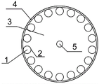
FIG. 2 is a coil rotor of the present invention;
FIG. 3 is a magnetic rotor of the present invention;
FIG. 4 is a schematic view of another coil rotor and magnet rotor combination of the present invention;
in the figure: 1-iron core, 2-coil, 3-coil guard plate, 4-coil rotor shell, 5-shaft, 6-magnetic rotor guard plate, 7-damping rubber, 8-permanent magnet steel, 9-magnetic rotor shell and 10-tire.
Detailed Description
The invention is further described with reference to the following drawings and detailed description.
Example 1
As shown in fig. 1, the wheel-driven dual-rotor range-extended generator device comprises a coil rotor consisting of an iron core 1, a coil 2, a coil guard plate 3 and a coil rotor shell 4, a shaft 5, and a magnetic rotor consisting of a magnetic rotor guard plate 6, damping rubber 7, permanent magnet steel 8, a magnetic rotor shell 9 and a tire 10.
When the wheel-driven dual-rotor range-increasing generator device is vertically placed, namely the shaft 5 is placed parallel to the ground, the magnetic rotor tire 10 is in contact with the ground, the coil rotor is tightly contacted with the magnetic rotor in the gravity direction, away from the magnetic rotor in the direction opposite to the gravity, the shaft 5 transfers the force to the coil rotor and starts to rotate under the action of the external force, and simultaneously the coil rotor rolls the magnetic rotor, the magnetic rotor starts to rotate along with the coil rotor, in the rolling direction, one coil rotor approaches the magnetic rotor, cuts magnetic lines of force, increases the magnetic flux in the coil, in the opposite direction of rolling, the other coil rotor is far away from the magnetic rotor to cut magnetic lines of force, so that the magnetic flux in the coil is reduced, each coil is close to or far away from the permanent magnet once in each rotation period, the size of the magnetic flux in the coil is changed to generate electromotive force, and when the coil is connected with a load, current is output.
Example 2
As shown in fig. 4, the wheel-driven dual-rotor range-extended generator device comprises a coil rotor consisting of an iron core 1, a coil 2, a coil guard plate 3 and a coil rotor shell 4, a shaft 5, and a magnetic rotor consisting of a magnetic rotor guard plate 6, damping rubber 7, permanent magnet steel 8, a magnetic rotor shell 9 and a tire 10.
When the wheel-following dual-rotor range-increasing generator device is vertically placed, namely the shaft 5 is placed parallel to the ground, the magnetic rotor tire 10 is in contact with the ground, the coil rotors are tightly contacted with the magnetic rotors in the gravity direction and far away from the magnetic rotors in the gravity reverse direction, the shaft 5 transmits force to the coil rotors and starts to rotate under the action of external force, the coil rotors roll the magnetic rotors, the magnetic rotors start to rotate along with the coil rotors, one coil rotor is close to the magnetic rotors in the rolling direction to increase the magnetic flux in the coil, the other coil rotor is far away from the magnetic rotors in the rolling reverse direction to reduce the magnetic flux in the coil, each coil is close to or far away from a permanent magnet once in each rotation period, the size change of the magnetic flux in the coil generates electromotive force, and when the load is connected, current is output.
The invention is described above with reference to the accompanying drawings, it is obvious that the implementation of the invention is not limited to the above, and it is within the scope of the invention to use the method concept and solution of the invention in various modifications or to apply the concept and solution of the invention directly to other applications without modification.
Claims (3)
1. The utility model provides a wheel follow-up birotor increases journey generator device which characterized in that: the dual-rotor range-extended generator device comprises a coil rotor, a shaft (5) and a magnetic rotor, wherein the coil rotor consists of an iron core (1), a coil (2), a coil guard plate (3) and a coil rotor shell (4), and the magnetic rotor consists of a magnetic rotor guard plate (6), damping rubber (7), permanent magnetic steel (8), a magnetic rotor shell (9) and a tire (10);
an iron core (1), a coil (2) and a coil guard plate (3) of the coil rotor are fixedly connected with a coil rotor shell (4);
a magnetic rotor guard plate (6), vibration reduction rubber (7) and permanent magnetic steel (8) of the magnetic rotor are fixedly connected with a magnetic rotor shell (9);
the coil rotor and the magnetic rotor are in rolling friction connection, non-fixed connection, between the coil rotor shell (4) and the magnetic rotor shell (9);
the shaft (5) is connected with the vehicle body;
when the coil rotor starts to rotate, the coil rotor rolls the magnetic rotor, and the magnetic rotor starts to rotate along with the coil rotor;
the shaft (5) transmits force to the coil rotor and starts to rotate under the action of external force;
the magnetic rotor shell (9) is fixedly connected with a tire (10).
2. The wheel-follower dual-rotor range-extending generator device of claim 1, wherein: the iron core (1) of the coil rotor is made of a magnetic material, a non-magnetic material or a hollow core.
3. The wheel-follower dual-rotor range-extending generator device of claim 1, wherein: in the rolling direction, the coil rotor is close to the magnetic rotor to cut magnetic lines of force, so that the magnetic flux in the coil is increased, in the reverse rolling direction, the coil rotor is far away from the magnetic rotor to cut the magnetic lines of force, so that the magnetic flux in the coil is reduced, the size of the magnetic flux in the coil changes circularly to generate electromotive force to generate electricity, and when a load is externally connected, current is output.
Priority Applications (1)
| Application Number | Priority Date | Filing Date | Title |
|---|---|---|---|
| CN201710235323.2A CN106941304B (en) | 2017-04-12 | 2017-04-12 | Wheel follow-up dual-rotor range-extending generator |
Applications Claiming Priority (1)
| Application Number | Priority Date | Filing Date | Title |
|---|---|---|---|
| CN201710235323.2A CN106941304B (en) | 2017-04-12 | 2017-04-12 | Wheel follow-up dual-rotor range-extending generator |
Publications (2)
| Publication Number | Publication Date |
|---|---|
| CN106941304A CN106941304A (en) | 2017-07-11 |
| CN106941304B true CN106941304B (en) | 2021-11-23 |
Family
ID=59464206
Family Applications (1)
| Application Number | Title | Priority Date | Filing Date |
|---|---|---|---|
| CN201710235323.2A Active CN106941304B (en) | 2017-04-12 | 2017-04-12 | Wheel follow-up dual-rotor range-extending generator |
Country Status (1)
| Country | Link |
|---|---|
| CN (1) | CN106941304B (en) |
Families Citing this family (1)
| Publication number | Priority date | Publication date | Assignee | Title |
|---|---|---|---|---|
| CN111697787B (en) * | 2020-06-11 | 2021-11-30 | 广东电网有限责任公司 | Magnetomotive system and magnetomotive transportation equipment |
Family Cites Families (7)
| Publication number | Priority date | Publication date | Assignee | Title |
|---|---|---|---|---|
| GB894242A (en) * | 1959-07-30 | 1962-04-18 | Fichtel & Sachs Ag | Improvements in and relating to wheel hubs with a built-in dynamo |
| JP2010011717A (en) * | 2008-06-24 | 2010-01-14 | Fukuichi Yuki | Roll-type generator |
| CN102739000A (en) * | 2011-04-12 | 2012-10-17 | 周智庆 | Eccentric rolling rotor variable reluctance motor |
| CN102303537A (en) * | 2011-06-23 | 2012-01-04 | 方子林 | Electric vehicle with two-way operating circulation generator |
| DE102012008141A1 (en) * | 2012-01-20 | 2013-10-24 | Dieter Brox | Rotary current generator for generating three-phase alternating current, has retaining wing that rotates relative to short-circuit ring rotor that is provided with roller bearing, and cam that is provided eccentric to engine shaft |
| JP2013162677A (en) * | 2012-02-07 | 2013-08-19 | Denso Corp | Axial gap type rotary electric machine and wheel |
| US20150288249A1 (en) * | 2014-04-03 | 2015-10-08 | Schaeffler Technologies AG & Co. KG | Eccentric motor |
-
2017
- 2017-04-12 CN CN201710235323.2A patent/CN106941304B/en active Active
Also Published As
| Publication number | Publication date |
|---|---|
| CN106941304A (en) | 2017-07-11 |
Similar Documents
| Publication | Publication Date | Title |
|---|---|---|
| CN102005877B (en) | Energy-saving hub motor | |
| JP2014520496A (en) | Electric power generation and charging equipment for electric vehicles | |
| CN101797896A (en) | Electric automobile capable of feeding back energy | |
| CN102390275A (en) | Electromagnetic braking device of electric automobile with function of energy recovery and work method thereof | |
| CN201044398Y (en) | Self-generator of minitype electric vehicle | |
| CN201204530Y (en) | A permanent magnet synchronous hub motor for direct driving of electric vehicle wheels | |
| CN101973203A (en) | Pure self-power generation environmental-friendly electric automobile without additional charge | |
| CN206277951U (en) | A kind of automobile tire device with generating function | |
| CN103051108A (en) | Disc-type excitation multi-pole brushless single-phase alternating current hub generator of automobile | |
| CN103280940A (en) | Moving motor and electric vehicle | |
| CN204258527U (en) | Vehicle-mounted energy accumulation device for fly wheel | |
| CN205220210U (en) | Battery -operated motor cycle front wheel with generating function | |
| CN106941304A (en) | A kind of wheel is servo-actuated birotor and increases journey generator | |
| CN216122093U (en) | Brushless motor with generator device for electric vehicle wheel | |
| CN206528352U (en) | A kind of automobile regeneration brake system | |
| CN104505975B (en) | On-board flywheel energy storage device | |
| CN203119694U (en) | Rim driving force generating set | |
| CN205239170U (en) | Photovoltaic energy car | |
| CN212708971U (en) | Power control system of electric tricycle | |
| CN202260591U (en) | Reverse charging device for electric bicycle | |
| CN215897496U (en) | Hub reduction motor | |
| CN203995732U (en) | A kind of wind power generation electronlmobil | |
| CN202320697U (en) | Electric bicycle with power generator | |
| CN202906552U (en) | Tyre generating device | |
| CN201729253U (en) | Electric car |
Legal Events
| Date | Code | Title | Description |
|---|---|---|---|
| PB01 | Publication | ||
| PB01 | Publication | ||
| SE01 | Entry into force of request for substantive examination | ||
| SE01 | Entry into force of request for substantive examination | ||
| GR01 | Patent grant | ||
| GR01 | Patent grant |