CN106852316B - Bird repelling device - Google Patents
Bird repelling device Download PDFInfo
- Publication number
- CN106852316B CN106852316B CN201611000095.2A CN201611000095A CN106852316B CN 106852316 B CN106852316 B CN 106852316B CN 201611000095 A CN201611000095 A CN 201611000095A CN 106852316 B CN106852316 B CN 106852316B
- Authority
- CN
- China
- Prior art keywords
- cavity
- microwave induction
- way
- bird repelling
- fixed
- Prior art date
- Legal status (The legal status is an assumption and is not a legal conclusion. Google has not performed a legal analysis and makes no representation as to the accuracy of the status listed.)
- Active
Links
Images


Classifications
-
- A—HUMAN NECESSITIES
- A01—AGRICULTURE; FORESTRY; ANIMAL HUSBANDRY; HUNTING; TRAPPING; FISHING
- A01M—CATCHING, TRAPPING OR SCARING OF ANIMALS; APPARATUS FOR THE DESTRUCTION OF NOXIOUS ANIMALS OR NOXIOUS PLANTS
- A01M29/00—Scaring or repelling devices, e.g. bird-scaring apparatus
-
- G—PHYSICS
- G01—MEASURING; TESTING
- G01V—GEOPHYSICS; GRAVITATIONAL MEASUREMENTS; DETECTING MASSES OR OBJECTS; TAGS
- G01V3/00—Electric or magnetic prospecting or detecting; Measuring magnetic field characteristics of the earth, e.g. declination, deviation
- G01V3/12—Electric or magnetic prospecting or detecting; Measuring magnetic field characteristics of the earth, e.g. declination, deviation operating with electromagnetic waves
-
- H—ELECTRICITY
- H02—GENERATION; CONVERSION OR DISTRIBUTION OF ELECTRIC POWER
- H02J—ELECTRIC POWER NETWORKS; CIRCUIT ARRANGEMENTS OR SYSTEMS FOR SUPPLYING OR DISTRIBUTING ELECTRIC POWER; SYSTEMS FOR STORING ELECTRIC ENERGY
- H02J7/00—Circuit arrangements for charging or discharging batteries or for supplying loads from batteries
- H02J7/34—Parallel operation in networks using both storage and other DC sources, e.g. providing buffering
- H02J7/35—Parallel operation in networks using both storage and other DC sources, e.g. providing buffering with light sensitive cells
Landscapes
- Life Sciences & Earth Sciences (AREA)
- Engineering & Computer Science (AREA)
- Remote Sensing (AREA)
- Physics & Mathematics (AREA)
- Pest Control & Pesticides (AREA)
- Environmental & Geological Engineering (AREA)
- Zoology (AREA)
- Environmental Sciences (AREA)
- Insects & Arthropods (AREA)
- Electromagnetism (AREA)
- Birds (AREA)
- Wood Science & Technology (AREA)
- Geology (AREA)
- General Life Sciences & Earth Sciences (AREA)
- General Physics & Mathematics (AREA)
- Geophysics (AREA)
- Power Engineering (AREA)
- Catching Or Destruction (AREA)
Abstract
本发明提供一种驱鸟装置,包括:具有平顶的腔体、固定装置、太阳能发电装置、设置于所述腔体外表面的微波感应控制装置、固定于所述腔体内部底面上的高压气体喷气装置和微波感应开关以及电源。所述腔体的侧面上具有多个出气口;所述微波感应控制装置包括一个或多个微波感应控制器;所述单向高压阀门喷气孔与所述腔体上的多个出气口分别通过喷气管连接;所述太阳能发电装置与所述电源连接,为所述电源供电;所述太阳能发电装置与所述电源连接,为所述电源供电;所述电源分别与所述微波感应开关、所述微波感应控制装置、所述电子单向控制阀电连接,为它们供电;所述腔体固定于所述固定装置上,所述固定装置固定于电线杆塔的横担上。
The invention provides a bird repelling device, comprising: a cavity with a flat top, a fixing device, a solar power generation device, a microwave induction control device arranged on the outer surface of the cavity, and a high-pressure gas fixed on the inner bottom surface of the cavity Jet device and microwave induction switch and power supply. There are a plurality of gas outlets on the side of the cavity; the microwave induction control device includes one or more microwave induction controllers; the gas injection hole of the one-way high-pressure valve passes through the plurality of gas outlets on the cavity respectively. connected to the jet pipe; the solar power generation device is connected to the power supply to supply power to the power supply; the solar power generation device is connected to the power supply to supply power to the power supply; the power supply is connected to the microwave induction switch, the The microwave induction control device and the electronic one-way control valve are electrically connected to supply power to them; the cavity is fixed on the fixing device, and the fixing device is fixed on the cross arm of the utility pole.
Description
技术领域technical field
本发明涉及电子设备领域,尤其涉及一种驱鸟装置。The invention relates to the field of electronic equipment, in particular to a bird repelling device.
背景技术Background technique
架空送电线路大多运行在荒山野外,覆盖面广,生态环境又变化无常,还常常受到鸟类活动的影响。目前国内外变电站主要驱鸟装置有风车式驱鸟装置、超声波驱鸟装置、图形惊吓驱鸟装置等,但是这些传统的驱鸟方式因为对鸟类容易产生适应性且受防护范围的限制,驱鸟效果都不太理想,因此鸟害引起的输电线路异常、事故数量仍呈逐年上升趋势,这给输送电线路的安全运行带来严重的后果。Most of the overhead power transmission lines run in the wilderness of barren mountains, covering a wide area, and the ecological environment is volatile, and is often affected by bird activities. At present, the main bird repelling devices in substations at home and abroad include windmill bird repelling devices, ultrasonic bird repelling devices, graphic frightening bird repelling devices, etc. However, these traditional bird repelling methods are easy to adapt to birds and are limited by the protection range. The effect of birds is not ideal, so the number of abnormal transmission lines and accidents caused by bird damage is still on the rise year by year, which brings serious consequences to the safe operation of transmission lines.
发明内容Contents of the invention
为解决现有存在的技术问题,本发明提供一种驱鸟装置,其能驱赶在电线杆塔周围驻留的鸟类。In order to solve the existing technical problems, the present invention provides a bird repelling device, which can repel birds staying around electric poles and towers.
为达到上述目的,本发明实施例的技术方案是这样实现的:In order to achieve the above object, the technical solution of the embodiment of the present invention is achieved in this way:
根据本发明,提供一种驱鸟装置,其包括:具有平顶的腔体、固定装置、太阳能发电装置、设置于所述腔体外表面的微波感应控制装置、固定于所述腔体内部底面上的高压气体喷气装置和微波感应开关以及电源。所述高压气体喷气装置包括用于容纳高压气体的高压气瓶和用于密封高压气瓶瓶口的三项阀,所述三项阀中位于瓶口两侧的阀中一个是单向充气阀,一个是电子单向控制阀,在电子单向控制阀的一端设置有单向高压阀门喷气孔,所述单向充气阀位于所述腔体的外面;所述腔体的侧面上具有多个出气口;所述微波感应控制装置包括一个或多个微波感应控制器;所述单向高压阀门喷气孔与所述腔体上的多个出气口分别通过喷气管连接;所述太阳能发电装置与所述电源连接,为所述电源供电;所述电源分别与所述微波感应开关、所述微波感应控制装置、所述电子单向控制阀电连接,为它们供电;所述微波感应控制装置与所述微波感应开关电连接,所述微波感应开关与所述电子单向控制阀电连接;所述腔体固定于所述固定装置上,所述固定装置固定于电线杆塔的横担上。According to the present invention, a bird repelling device is provided, which includes: a cavity with a flat top, a fixing device, a solar power generation device, a microwave induction control device arranged on the outer surface of the cavity, and fixed on the inner bottom surface of the cavity High-pressure gas injection device and microwave induction switch and power supply. The high-pressure gas injection device includes a high-pressure gas cylinder for containing high-pressure gas and a three-way valve for sealing the mouth of the high-pressure gas cylinder, one of the valves on both sides of the mouth of the three-way valve is a one-way inflation valve , one is an electronic one-way control valve, one end of the electronic one-way control valve is provided with a one-way high-pressure valve air injection hole, and the one-way inflation valve is located outside the cavity; the side of the cavity has a plurality of Gas outlet; the microwave induction control device includes one or more microwave induction controllers; the gas injection hole of the one-way high-pressure valve is connected to a plurality of gas outlets on the cavity respectively through gas injection pipes; the solar power generation device and The power supply is connected to supply power to the power supply; the power supply is electrically connected to the microwave induction switch, the microwave induction control device, and the electronic one-way control valve respectively to supply power to them; the microwave induction control device is connected to the microwave induction control device. The microwave induction switch is electrically connected, and the microwave induction switch is electrically connected with the electronic one-way control valve; the cavity is fixed on the fixing device, and the fixing device is fixed on the cross arm of the utility pole.
可选地,所述固定装置由固定板支架制作。Optionally, the fixing device is made of a fixing plate bracket.
可选地,所述固定板支架包括一端带有U型钩的固定板、一个或多个螺栓拉钩、以及一个或多个螺栓拉钩滑槽,其中所述螺栓拉钩滑槽平行于所述固定板的长度方向从所述固定板中间位置向带有U型钩侧开设,螺栓拉钩的数量与螺栓拉钩滑槽的数量对应,且所述螺栓拉钩分别固定于所述螺栓拉钩滑槽中,所述腔体固定于所述固定板不带有U型钩的一端且与所述U型钩分别位于所述固定板的两侧。Optionally, the fixing plate bracket includes a fixing plate with a U-shaped hook at one end, one or more bolt draw hooks, and one or more bolt draw hook chute, wherein the bolt draw hook chute is parallel to the fixing plate The length direction of the fixed plate is opened from the middle position of the fixing plate to the side with the U-shaped hook, the number of bolt hooks corresponds to the number of bolt hook chute, and the bolt hooks are respectively fixed in the bolt hook chute, the The cavity is fixed on one end of the fixing plate without the U-shaped hook and is respectively located on two sides of the fixing plate with the U-shaped hook.
可选地,所述太阳能发电装置固定于所述腔体的平顶上且朝向南或西南方向。Optionally, the solar power generation device is fixed on the flat top of the cavity and faces south or southwest.
可选地,所述腔体为具有锥形上部的圆柱体。Optionally, the cavity is a cylinder with a tapered upper portion.
可选地,所述微波感应控制装置设置于所述腔体的圆柱体的柱面外侧。Optionally, the microwave induction control device is arranged outside the cylindrical surface of the cylinder of the cavity.
可选地,所述微波感应控制装置位于距所述腔体的圆柱体的底面10厘米的位置处。Optionally, the microwave induction control device is located 10 cm away from the bottom surface of the cylinder of the cavity.
可选地,所述腔体上的喷气孔分散地位于所述腔体的圆柱体的柱面上。Optionally, the gas injection holes on the cavity are scattered on the cylindrical surface of the cylinder of the cavity.
可选地,所述腔体上的喷气孔分散地位于距所述腔体的圆柱体的底面10厘米的柱面上。Optionally, the jet holes on the cavity are scattered on a
可选地,当所述微波感应控制装置包含多个微波感应控制器时,每个微波感应控制器具有外壳。Optionally, when the microwave induction control device includes a plurality of microwave induction controllers, each microwave induction controller has a housing.
可选地,所述外壳为中间具有开口的封闭外壳,且所述开口大于或等于所述腔体上设置的喷气孔,所述微波感应控制器分别固定于所述腔体的出气口外侧,所述微波感应控制器的数量与所述腔体的出气口的数量相同。Optionally, the housing is a closed housing with an opening in the middle, and the opening is larger than or equal to the gas injection hole provided on the cavity, and the microwave induction controllers are respectively fixed on the outside of the gas outlet of the cavity, The number of the microwave induction controller is the same as the number of the air outlets of the cavity.
可选地,连接所述单向高压阀门喷气孔和所述腔体上的多个出气口的所述喷气管为具有多个子输出管的管子,所述喷气管的一端固定于所述单向高压阀门喷气孔,所述喷气管的多个子输出管的出口分别固定于所述腔体上的多个出气口的位置处。Optionally, the air injection pipe connecting the air injection hole of the one-way high-pressure valve and the multiple air outlets on the cavity is a pipe with multiple sub-output pipes, and one end of the air injection pipe is fixed to the one-way valve. The high-pressure valve gas injection hole, the outlets of the multiple sub-output pipes of the gas injection pipe are respectively fixed at the positions of the multiple gas outlets on the cavity.
可选地,所述单向高压阀门喷气孔处设置有多个子喷气孔,每个子喷气孔通过一喷气管与所述腔体上的其中一个出气口连接,所述喷气管与所述子喷气孔的数量相同。Optionally, a plurality of sub-jet holes are provided at the jet hole of the one-way high-pressure valve, and each sub-jet hole is connected to one of the gas outlets on the cavity through a jet tube, and the jet tube is connected to the sub-jet holes. The number of holes is the same.
附图说明Description of drawings
在附图(其不一定是按比例绘制的)中,相似的附图标记可在不同的视图中描述相似的部件。具有不同字母后缀的相似附图标记可表示相似部件的不同示例。附图以示例而非限制的方式大体示出了本文中所讨论的各个实施例。In the drawings (which are not necessarily drawn to scale), like reference numerals may describe like parts in different views. Similar reference numbers with different letter suffixes may indicate different instances of similar components. The drawings generally illustrate the various embodiments discussed herein, by way of example and not limitation.
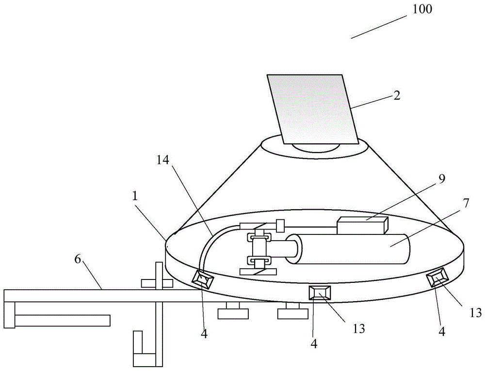
图1示出了根据本发明的一种实施方式的驱鸟装置的整体结构示意图;Figure 1 shows a schematic diagram of the overall structure of a bird repelling device according to an embodiment of the present invention;
图2示出了根据本发明的高压气体喷气装置的结构示意图;Fig. 2 shows the structural representation of the high-pressure gas injection device according to the present invention;
图3示出了根据本发明的固定板支架的正视图;Figure 3 shows a front view of a fixed plate bracket according to the present invention;
图4示出了根据本发明的固定板支架的立体图;Figure 4 shows a perspective view of a fixed plate bracket according to the present invention;
图5示出了根据本发明的安装在电线杆塔上的角铁上的固定板支架的正视图;Fig. 5 shows the front view of the fixed plate bracket installed on the angle iron on the utility pole tower according to the present invention;
图6示出了根据本发明的安装有微波感应控制装置和出气口的腔体的圆柱体部分的结构示意图;以及Fig. 6 shows a schematic structural view of the cylindrical part of the cavity equipped with a microwave induction control device and an air outlet according to the present invention; and
图7示出了根据本发明的驱鸟装置的电路连接图。Fig. 7 shows the circuit connection diagram of the bird repelling device according to the present invention.
具体实施方式detailed description
下面将参照附图更详细地描述本公开的示例性实施例。虽然附图中显示了本公开的示例性实施例,然而应当理解,可以以各种形式实现本公开而不应被这里阐述的实施例所限制。相反,提供这些实施例是为了能够更透彻地理解本公开,并且能够将本公开的范围完整的传达给本领域的技术人员。Exemplary embodiments of the present disclosure will be described in more detail below with reference to the accompanying drawings. Although exemplary embodiments of the present disclosure are shown in the drawings, it should be understood that the present disclosure may be embodied in various forms and should not be limited by the embodiments set forth herein. Rather, these embodiments are provided for more thorough understanding of the present disclosure and to fully convey the scope of the present disclosure to those skilled in the art.
图1示出了根据本发明的驱鸟装置的结构示意图。如图1所示,本发明的驱鸟装置100包括具有平顶的腔体1、固定装置6、太阳能发电装置2、设置于腔体1外表面的微波感应控制装置4、固定于腔体1内部底面上的高压气体喷气装置和微波感应开关9以及电源(图中未示出)。Fig. 1 shows a schematic structural diagram of a bird repelling device according to the present invention. As shown in Figure 1, the
腔体1基本上是封闭的,用于保护腔体1内的设备不受恶劣天气(例如风、雨、雪、雹等)的影响而被损坏。可选地,腔体1可以采用上部具有锥体形状的圆柱体,如图1所示,即该腔体1的上部为锥体形状,下部为圆柱体形状。但本发明并不限定腔体1的形状,例如腔体1的下部也可以采用棱柱体形状,另外腔体1还可以采用其它多种形状,例如柱体形状或者其它形状。The
在腔体1的平顶上面放置有太阳能发电装置2。太阳能发电装置2用于接收太阳能并将其转换成电能,为位于腔体1内部的电源(未示出)供电。所述电源可以采用蓄电池设备。A solar
在腔体1上设置有多个出气口13,优选地,所述多个出气口13分散地位于腔体1的不同方向上。当腔体1采用如图1所示的上部具有锥体形状的圆柱体时,可选地,所述多个出气口13分散地位于腔体1的圆柱体的侧面的一个圆周上,从而分别朝向不同的方向。优选地,所述多个出气口13位于腔体1的圆柱体的柱面上且距离腔体1的底面大约10厘米的位置处。A plurality of
高压气体喷气装置20,如图2所示,包括用于容纳高压气体的高压气瓶7、和用于密封高压气瓶瓶口的三项阀,所述三项阀中有两个阀位于瓶口两侧,其中一个阀是单向充气阀10,单向充气阀10在高压气体喷气装置20固定于腔体1的底面上时位于腔体1的底面的外面,以便在本发明的驱鸟装置100安装于电线杆塔的横担上以后方便给高压气瓶7充气,而不需要拆卸本发明的驱鸟装置100或者将高压气体喷气装置20从腔体1中取出。位于高压气瓶7瓶口两侧的另一个阀包括电子单向控制阀8和单向高压阀门喷气孔11,电子单向控制阀8和单向高压阀门喷气孔11分别设置于该阀的两端,如图2所示,由电子单向控制阀8控制单向高压阀门喷气孔11的接通和关闭,即控制单向高压阀门喷气孔11的开孔打开而喷气或者关闭而停止喷气。当然,这只是一种实施方式,本发明并不限定高压气瓶7以三项阀密封,也可以采用两项阀或其它方式,其中单向充气阀10可以设置于高压气瓶7的任何位置,例如在高压气瓶7放置于腔体1的底面时,单向充气阀10可以位于高压气瓶7的朝向腔体的底面的一侧,或者位于高压气瓶7的瓶底而从腔体1的柱形侧面伸出等等。The high-pressure
其中,单向高压阀门喷气孔11与腔体1上的多个出气口13分别通过喷气管14连接。可选地,连接单向高压阀门喷气孔11和腔体1上的多个出气口13的所述喷气管14为具有多个子输出管的管子,所述喷气管14的一端固定于所述单向高压阀门喷气孔11,所述喷气管14的多个子输出管的出口分别固定于腔体1上的多个出气口13的位置处。Wherein, the
可选地,所述单向高压阀门喷气孔11处还可以设置有多个子喷气孔,每个子喷气孔通过一喷气管与腔体1上的其中一个出气口13连接,所述喷气管14与所述子喷气孔的数量相同。Optionally, a plurality of sub-jet holes may also be provided at the
另外,所述喷气管14或者其子输出管在固定于腔体1的出气口13处的一侧的管口管径与出气口相适配,例如通过卡合的方式固定于出气口13处。本发明不限定喷气管14与单向高压阀门喷气孔11以及喷气管14与出气口13的连接方式,只要能够固定连接,使从单向高压阀门喷气孔11喷出的高压气体从出气口13顺利喷出即可。In addition, the diameter of the
固定装置6用于将本发明的驱鸟装置100固定于电线杆塔的横担上,例如,可以固定于电线杆塔的绝缘子悬挂点的横担处。可选地,固定装置6可以由图3至图5所示的固定板支架6制作。如图3-5所示,固定板支架6包括一端带有U型钩的固定板63、一个或多个螺栓拉钩61、以及一个或多个螺栓拉钩滑槽64,其中螺栓拉钩滑槽64平行于固定板63的长度方向且从固定板63中间位置向带有U型钩侧开设,螺栓拉钩61的数量与螺栓拉钩滑槽64的数量相同,且每个螺栓拉钩滑槽64中固定有一个螺栓拉钩61,例如螺栓拉钩61通过螺母固定于螺栓拉钩滑槽64中。当有两个以上螺栓拉钩滑槽64时,螺栓拉钩滑槽64均匀分布在固定板63的中间但偏U型钩的一侧,如图4所示。The fixing
螺栓拉钩61是一端带有U型拉钩的竖杆,如图3和5所示,螺栓拉钩61垂直于固定板63的板面而放置于螺栓拉钩滑槽64中,且螺栓拉钩61的U型拉钩朝向固定板63的U型钩一侧,从而使电线杆塔的横担上的角铁12的两边可以分别置于螺栓拉钩61的U型拉钩中和固定板63的U型钩中,从而可以将本发明的驱鸟装置100固定于电线杆塔的横担上。为了固定牢固,在固定板63的U型钩下方通过螺丝62将所述U型钩固定于电线杆塔的横担的角铁12上,所用螺丝62的数量根据需要而定,本发明对此不做限定。The
腔体1固定于固定板63不带有U型钩的一端上且与所述U型钩分别位于固定板63的板面的两侧,例如,如图1所示,U型钩位于固定板63的左端,腔体1固定于固定板63的右端,而且U型钩位于固定板63的板面的下面,而腔体1位于固定板63的板面的上面。腔体1可以通过例如螺钉62固定于固定板63的板面上,图4中采用4个螺钉62将腔体1固定于固定板63的板面的右侧。这里,所采用的螺钉62的数量根据需要而定,例如可以采用2个、或4个或更多,本发明对此不做限定。
微波感应控制装置4可以包括一个或多个微波感应控制器以及容纳微波感应控制器的外壳。微波感应控制装置4固定于靠近腔体1下部的外侧面上,用于感测鸟是否落在电线杆塔的横担附近或者横担上的绝缘子上。The microwave
当微波感应控制装置4包含多个微波感应控制器时,可选地,每个微波感应控制器具有一外壳,或者数个微波感应控制器封闭在一个外壳内。可选地,每个微波感应控制器的外壳为中间具有开口的封闭外壳,且所述开口大于或等于腔体1上设置的出气口13,微波感应控制装置4固定于腔体1的出气口13外侧,且使外壳上的开口与腔体1的出气口13对应放置,这时封装有微波感应控制器的壳体的数量与腔体1的出气口13的数量相同。When the microwave
另外,可选地,所述微波感应控制器的外壳上不开设有开口,微波感应控制装置4只是分散地放置于腔体1的外侧面上且位于不开设有出气口13的位置,可选地,放置于出气口13的周围。其中,所述微波感应控制器的外壳可以制作成方形、圆形、或其它形状等,可选地,使所述微波感应控制器的外壳与腔体1的侧面接触的面的形状与腔体1的侧面形状相适配。例如,当腔体1的下部为圆柱体形状时,微波感应控制装置4分散地放置于腔体1下部圆柱体的外侧面上且位于不开设有出气口13的位置,如图6所示,这时,可选地,微波感应控制器的外壳的与腔体1的圆柱体的柱面接触的面具有与所述柱面弧度一致的弧形。In addition, optionally, no opening is opened on the shell of the microwave induction controller, and the microwave
当腔体1采用如图1所示的上部具有锥体形状的圆柱体时,每个微波感应控制装置4可以分散地设置于腔体1的圆柱体的柱面外侧,例如,均匀地分布在圆柱体的柱面的某一圆周上,优选地,设置于距腔体1的圆柱体的底面10厘米的位置处。When the
但微波感应控制装置4不限于此种实施方式,例如,微波感应控制装置4还可以采用将多个微波感应控制器分散地放置于一个封闭外壳内,所述外壳与腔体1下部的外侧面形状相适应从而可以环绕在腔体1下部周围。在微波感应控制装置4的外壳上与腔体1上开设的出气口13对应的位置处分别开设有对应的开口。另外,可选地,微波感应控制装置4可以放置于腔体1上未开设有出气口13的位置,例如当腔体1的下部为圆柱体形状时,放置于腔体1的圆柱体柱面上的出气口13所位于的圆周的上方或下方或者其它不覆盖出气口13的位置上。But the microwave
太阳能发电装置2固定于腔体1的平顶上且使采集太阳能的一侧朝向南方或西南方向。图7示出了根据本发明的驱鸟装置的电路连接图。太阳能发电装置2与所述电源连接,为其提供电能。所述电源分别与微波感应开关9、微波感应控制装置4中的微波感应控制器、电子单向控制阀8电连接,为它们供电。微波感应控制装置4中的微波感应控制器与微波感应开关9电连接,微波感应开关9与电子单向控制阀电8连接。这样,当微波感应控制装置4中的任一微波感应控制器感测到鸟落在电线杆塔的横担附近或者其上的绝缘子附近时,就会产生控制信号并将所述控制信号发送给微波感应开关9,使微波感应开关9接通,从而使电子单向控制阀8通电,电子单向控制阀8控制单向高压阀门喷气孔11打开(打开或关闭的时间例如为0.5-5秒),这时高压气瓶7中的高压气体从单向高压阀门喷气孔11喷出,经所述喷气管14从腔体1上的出气口13向电线杆塔的横担或绝缘子周围喷出,由于高压气体冲力很大,强大的气流会惊吓落在横担附近或绝缘子上的鸟而使其飞离,从而避免鸟在横担或者横担的绝缘子上筑巢或在横担上留下粪便而影响变电设备的正常工作。当鸟类离开横担时,微波感应控制器将发送控制信号给微波感应开关9而使其断开电路,从而电子单向控制阀11关闭,高压气体停止从单向高压阀门喷气孔11喷出。可选地,所述电源可以放置于微波感应开关9中。The solar
通常采用两升的高压气瓶7大约可以喷射高压气体70-90次。当高压气瓶中的气体快要用完时,可以通过单向充气阀门10人工地为高压气瓶7充气,从而不需要拆卸本发明的驱鸟装置而更换高压气瓶,方便操作。Usually adopt the high-
本发明的驱鸟装置采用高压气体进行驱鸟,由于高压气体在高低温环境下都可以使用,不会像水、油、漆等材料,在低温时容易凝固,造成装置停止运行,另外,如果采用水、油、漆等材料,其材质不属于绝缘材料,喷出时容易对输电线路造成短路跳闸事故。The bird repelling device of the present invention uses high-pressure gas to drive birds, because the high-pressure gas can be used in high and low temperature environments, and will not be like water, oil, paint and other materials, which are easy to solidify at low temperatures, causing the device to stop running. In addition, if Water, oil, paint and other materials are used, and their materials are not insulating materials. When spraying out, it is easy to cause short-circuit tripping accidents to the transmission line.
本发明的驱鸟装置克服了现有驱鸟技术的不足,当鸟落到本发明的驱鸟装置附近时,该驱鸟装置电路就会接通,通过喷洒高压气体,产生的高压气流对鸟类产生惊吓,实现驱赶鸟类的作用,使鸟类自然放弃原有的环境而另觅新址(对于已经在横担上筑巢的情况而言)或者避免鸟类在横担或绝缘子上筑巢,从而保证输电线路的安全运行,而且还不会伤害鸟类。The bird repelling device of the present invention overcomes the deficiencies of the existing bird repelling technology. When a bird falls near the bird repelling device of the present invention, the circuit of the bird repelling device will be connected. It can scare the animals and realize the function of driving the birds, so that the birds will naturally abandon the original environment and find a new site (for the case of nesting on the cross-arm) or prevent the birds from building nests on the cross-arm or insulators , so as to ensure the safe operation of the transmission line, and it will not harm the birds.
在此处所提供的说明书中,说明了大量具体细节。然而,能够理解的是,本实用新型的实施例可以在没有这些具体细节的情况下实践。在一些实例中,并未详细示出公知的方法、结构和技术,以便不模糊对本说明书的理解。In the description provided herein, numerous specific details are set forth. However, it is understood that embodiments of the invention may be practiced without these specific details. In some instances, well-known methods, structures and techniques have not been shown in detail in order not to obscure the understanding of this description.
另外,以上所述的仅是本实用新型的原理和较佳的实施例。应当指出,对于本领域的普通技术人员来说,在本实用新型原理的基础上,还可以做出若干其它变型,这些变型也视为落入本实用新型的保护范围内。In addition, what is described above is only the principles and preferred embodiments of the present utility model. It should be pointed out that for those skilled in the art, several other modifications can be made on the basis of the principle of the utility model, and these modifications are also deemed to fall within the protection scope of the utility model.
此外,本领域的技术人员能够理解,不同实施例的特征的组合意味着处于本实用新型的范围之内并且形成不同的实施例。例如,在权利要求书中,所要求保护的实施例的任意之一都可以以任意的组合方式来使用。In addition, those skilled in the art can understand that the combination of features of different embodiments is meant to be within the scope of the present invention and form different embodiments. For example, in the claims, any one of the claimed embodiments can be used in any combination.
应该注意的是,上述实施例对本实用新型进行说明而不是对本实用新型进行限制,并且本领域技术人员在不脱离所附权利要求的范围的情况下可设计出替换实施例。在权利要求中,不应将位于括号之间的任何参考符号构造成对权利要求的限制。单词“包含”不排除存在未列在权利要求中的元件。位于元件之前的单词“一”或“一个”不排除存在多个这样的元件。It should be noted that the above-mentioned embodiments illustrate rather than limit the invention, and that those skilled in the art will be able to design alternative embodiments without departing from the scope of the appended claims. In the claims, any reference signs placed between parentheses shall not be construed as limiting the claim. The word "comprising" does not exclude the presence of elements not listed in a claim. The word "a" or "an" preceding an element does not exclude the presence of a plurality of such elements.
Claims (10)
Priority Applications (1)
| Application Number | Priority Date | Filing Date | Title |
|---|---|---|---|
| CN201611000095.2A CN106852316B (en) | 2016-11-14 | 2016-11-14 | Bird repelling device |
Applications Claiming Priority (1)
| Application Number | Priority Date | Filing Date | Title |
|---|---|---|---|
| CN201611000095.2A CN106852316B (en) | 2016-11-14 | 2016-11-14 | Bird repelling device |
Publications (2)
| Publication Number | Publication Date |
|---|---|
| CN106852316A CN106852316A (en) | 2017-06-16 |
| CN106852316B true CN106852316B (en) | 2023-01-06 |
Family
ID=59126845
Family Applications (1)
| Application Number | Title | Priority Date | Filing Date |
|---|---|---|---|
| CN201611000095.2A Active CN106852316B (en) | 2016-11-14 | 2016-11-14 | Bird repelling device |
Country Status (1)
| Country | Link |
|---|---|
| CN (1) | CN106852316B (en) |
Families Citing this family (3)
| Publication number | Priority date | Publication date | Assignee | Title |
|---|---|---|---|---|
| CN109418255B (en) * | 2017-08-18 | 2024-06-21 | 国网河南鄢陵县供电公司 | Compressed air bird repellent system for power line towers |
| CN109418254A (en) * | 2017-08-18 | 2019-03-05 | 和家慧 | Fanout free region power supply line bird repellent control method |
| CN109412072A (en) * | 2017-08-18 | 2019-03-01 | 和家慧 | The installation method of the anti-bird pest system of supply lines |
Family Cites Families (7)
| Publication number | Priority date | Publication date | Assignee | Title |
|---|---|---|---|---|
| US4573427A (en) * | 1982-06-14 | 1986-03-04 | Peter Konzak | Bird scaring device |
| NZ229862A (en) * | 1989-07-07 | 1993-01-27 | Alan Francis Gunn | Pivotable bird scaring gun automatically deployed at first light |
| CN2552221Y (en) * | 2002-05-14 | 2003-05-21 | 秦龙 | Device for preventing transmission line from birds trouble |
| KR101170022B1 (en) * | 2010-02-16 | 2012-08-01 | 주식회사 한성기건 | Device for elimination bird nest using compressed air |
| CN205305827U (en) * | 2016-01-19 | 2016-06-15 | 代安琪 | Distribution lines bird repellent device |
| CN205585177U (en) * | 2016-03-26 | 2016-09-21 | 重庆工业职业技术学院 | High -tension distributing line is bird repellent device for tower |
| CN206303076U (en) * | 2016-11-14 | 2017-07-07 | 国网冀北电力有限公司管理培训中心 | Scarer |
-
2016
- 2016-11-14 CN CN201611000095.2A patent/CN106852316B/en active Active
Also Published As
| Publication number | Publication date |
|---|---|
| CN106852316A (en) | 2017-06-16 |
Similar Documents
| Publication | Publication Date | Title |
|---|---|---|
| CN106614507B (en) | Bird repellent device | |
| CN107484752A (en) | A kind of high-voltage transmission line pole tower solar energy scarer and method | |
| CN205305827U (en) | Distribution lines bird repellent device | |
| CN106852316A (en) | Scarer | |
| CN206821815U (en) | Scarer | |
| CN206303076U (en) | Scarer | |
| CN206099039U (en) | Prevent transformer substation's lightning rod of charming appearance and behaviour vibration damage | |
| CN204499249U (en) | Wind whistle formula bird-scaring unit | |
| CN205624128U (en) | Spherical transmission line prevents bird cover | |
| CN201635487U (en) | Insulated Safety Fence | |
| CN206491214U (en) | A kind of power distribution network with can powered installation anti-driving birds away device | |
| CN201957657U (en) | Self-suction type wind power bird-driving device | |
| CN204860782U (en) | Transmission tower prevents bird mechanism | |
| CN204888503U (en) | Solar energy ultrasonic wave bird repellent device | |
| CN206801187U (en) | A kind of anti-bird pest cross-arm of 10KV circuits | |
| CN209152104U (en) | A kind of intelligent robot for driving animal for substation | |
| CN203942993U (en) | The anti-bird from building nest device of occupy-place formula tubulose | |
| CN207369965U (en) | A kind of wind-force catches up with bird to pierce | |
| CN204117832U (en) | Ring main unit and gas-insulated cabinet straight-through current transformer | |
| CN201639237U (en) | Anti-bird swivel for transmission lines | |
| CN111102134B (en) | High-voltage conductor corona effect generator | |
| CN102738601B (en) | Movable multifunctional external grounding device | |
| CN202855528U (en) | Power grid SF6 current transformer explosion-proof membrane protective cover | |
| CN203688604U (en) | Discharge rod for aging and withstand voltage test on GIS (Gas Insulated Switchgear) | |
| CN203646388U (en) | Electric wire tower bird repellent device |
Legal Events
| Date | Code | Title | Description |
|---|---|---|---|
| PB01 | Publication | ||
| PB01 | Publication | ||
| SE01 | Entry into force of request for substantive examination | ||
| SE01 | Entry into force of request for substantive examination | ||
| GR01 | Patent grant | ||
| GR01 | Patent grant |