CN106743921B - Novel automatic soft tissue stacking machine - Google Patents
Novel automatic soft tissue stacking machine Download PDFInfo
- Publication number
- CN106743921B CN106743921B CN201710088544.1A CN201710088544A CN106743921B CN 106743921 B CN106743921 B CN 106743921B CN 201710088544 A CN201710088544 A CN 201710088544A CN 106743921 B CN106743921 B CN 106743921B
- Authority
- CN
- China
- Prior art keywords
- separation
- separating
- lifting
- movable
- movable frame
- Prior art date
- Legal status (The legal status is an assumption and is not a legal conclusion. Google has not performed a legal analysis and makes no representation as to the accuracy of the status listed.)
- Expired - Fee Related
Links
- 210000004872 soft tissue Anatomy 0.000 title claims 4
- 238000000926 separation method Methods 0.000 claims abstract description 260
- 230000007246 mechanism Effects 0.000 claims abstract description 132
- 230000001360 synchronised effect Effects 0.000 claims abstract description 60
- 230000005540 biological transmission Effects 0.000 claims description 58
- 230000000694 effects Effects 0.000 claims 4
- 238000009434 installation Methods 0.000 claims 3
- 238000000605 extraction Methods 0.000 claims 1
- 210000001519 tissue Anatomy 0.000 claims 1
- 238000005086 pumping Methods 0.000 abstract description 14
- 238000000034 method Methods 0.000 description 5
- 238000010586 diagram Methods 0.000 description 3
- 230000009286 beneficial effect Effects 0.000 description 1
- 230000007812 deficiency Effects 0.000 description 1
- 238000004519 manufacturing process Methods 0.000 description 1
Images


Classifications
-
- B—PERFORMING OPERATIONS; TRANSPORTING
- B65—CONVEYING; PACKING; STORING; HANDLING THIN OR FILAMENTARY MATERIAL
- B65H—HANDLING THIN OR FILAMENTARY MATERIAL, e.g. SHEETS, WEBS, CABLES
- B65H33/00—Forming counted batches in delivery pile or stream of articles
- B65H33/06—Forming counted batches in delivery pile or stream of articles by displacing articles to define batches
-
- B—PERFORMING OPERATIONS; TRANSPORTING
- B65—CONVEYING; PACKING; STORING; HANDLING THIN OR FILAMENTARY MATERIAL
- B65H—HANDLING THIN OR FILAMENTARY MATERIAL, e.g. SHEETS, WEBS, CABLES
- B65H2701/00—Handled material; Storage means
- B65H2701/10—Handled articles or webs
- B65H2701/19—Specific article or web
- B65H2701/1924—Napkins or tissues, e.g. dressings, toweling, serviettes, kitchen paper and compresses
Landscapes
- Sheets, Magazines, And Separation Thereof (AREA)
Abstract
本发明公开了一种新式软抽纸自动分叠机,其机架装设弧形导送板、承接台板、顶部支撑架、软抽纸分离组件、自动承接组件、自动推送组件、水平输送带;软抽纸分离组件包括分离升降活动架、分离升降驱动机构、旋转分离机构、左、右侧活动分离机构以及左、右侧分离支承机构,旋转分离机构包括旋转分离安装座、旋转分离进给座、旋转分离进给气缸、旋转分离转盘、旋转分离驱动电机;左、右侧活动分离机构包括分离驱动电机、分离活动座、同步带传动机构、分离进给气缸、分离插板;左、右侧分离支承机构包括分离支承气缸、分离支承板。本发明能自动高效完成软抽纸分叠作业,结构设计新颖、自动化程度高、工作效率高且能够有效地节省人工成本。
The invention discloses a new type automatic stacking machine for soft pumping paper. The frame is equipped with an arc-shaped guide plate, a receiving platen, a top support frame, a soft paper pumping separation component, an automatic receiving component, an automatic pushing component, and horizontal conveying. Belt; the soft paper separation component includes a separation lifting movable frame, a separation lifting drive mechanism, a rotating separation mechanism, a left and right movable separation mechanism, and a left and right separation supporting mechanism. Feeding seat, rotary separation feed cylinder, rotary separation turntable, rotary separation drive motor; left and right movable separation mechanisms include separation drive motor, separation movable seat, synchronous belt drive mechanism, separation feed cylinder, separation insert plate; left, right The separation support mechanism on the right side comprises a separation support cylinder and a separation support plate. The invention can automatically and efficiently complete the folding operation of soft pumping paper, has novel structural design, high degree of automation, high work efficiency and can effectively save labor costs.
Description
技术领域technical field
本发明涉及自动化设备技术领域,尤其涉及一种新式软抽纸自动分叠机。The invention relates to the technical field of automation equipment, in particular to a new type of automatic stacking machine for soft pumping paper.
背景技术Background technique
在软抽纸加工过程中,高速打纸机将软抽纸连续送出;在生产软抽纸包过程中,需要将高速打纸机送出的软抽纸进行分离。During the processing of soft paper, the high-speed paper machine continuously sends out the soft paper; during the production of soft paper packs, it is necessary to separate the soft paper sent out by the high-speed paper machine.
其中,现有技术一般采用人工作业的方式来进行软抽纸分离,工作效率低、自动化程度低且人工成本高。Among them, the prior art generally adopts manual operation to separate soft paper, which has low work efficiency, low degree of automation and high labor cost.
发明内容Contents of the invention
本发明的目的在于针对现有技术的不足而提供一种新式软抽纸自动分叠机,该新式软抽纸自动分叠机结构设计新颖、自动化程度高、工作效率高且能够有效地节省人工成本。The purpose of the present invention is to provide a new type of soft paper automatic stacking machine for the deficiencies of the prior art. The new type of soft paper automatic stacking machine has novel structure design, high degree of automation, high work efficiency and can effectively save labor. cost.
为达到上述目的,本发明通过以下技术方案来实现。In order to achieve the above object, the present invention is achieved through the following technical solutions.
一种新式软抽纸自动分叠机,包括有机架,机架装设有呈90度圆弧形的弧形导送板、位于弧形导送板后端侧且呈水平横向布置的承接台板,机架的上端部于承接台板的正上方装设有顶部支撑架,顶部支撑架的前端部于弧形导送板的上端侧装设有软抽纸分离组件,顶部支撑架于软抽纸分离组件的后端侧装设有自动承接组件、位于自动承接组件后端侧的自动推送组件,机架于承接台板的后端侧装设有水平输送带;A new type of soft paper automatic stacking machine, including a frame, the frame is equipped with an arc-shaped guide plate in a 90-degree arc shape, and a receiving plate arranged horizontally and horizontally on the rear end side of the arc-shaped guide plate. Platen, the upper end of the frame is provided with a top supporting frame directly above the receiving platen, and the front end of the top supporting frame is equipped with a soft paper separation assembly on the upper end side of the arc-shaped guide plate. The rear end of the soft paper separation assembly is equipped with an automatic receiving assembly and an automatic pushing assembly located at the rear end of the automatic receiving assembly, and the frame is equipped with a horizontal conveyor belt on the rear end of the receiving platen;
软抽纸分离组件包括有可相对上下活动地装设于顶部支撑架前端部的分离升降活动架,顶部支撑架的前端部于分离升降活动架的上端侧装设有分离升降驱动机构,分离升降驱动机构与分离升降活动架驱动连接,分离升降活动架的中间位置装设有旋转分离机构,旋转分离机构包括有螺装于分离升降活动架中间位置的旋转分离安装座,旋转分离安装座可相对前后活动地装设有旋转分离进给座,旋转分离安装座对应旋转分离进给座装设有旋转分离进给气缸,旋转分离进给气缸的活塞杆外延端部与旋转分离进给座连接,旋转分离进给座的前端部可相对转动地装设有呈圆盘形状的旋转分离转盘,旋转分离进给座的后端部于旋转分离转盘的后端侧装设有旋转分离驱动电机,旋转分离驱动电机的动力输出轴与旋转分离转盘驱动连接;The soft paper separation component includes a separation lifting movable frame that is relatively movable up and down at the front end of the top support frame. The front end of the top support frame is equipped with a separation lifting drive mechanism on the upper end side of the separation lifting movable frame. The driving mechanism is driven and connected with the separation and lifting movable frame. The middle position of the separation and lifting movable frame is equipped with a rotating separation mechanism. A rotary separation feed seat is installed front and rear movable, and a rotary separation feed cylinder is installed corresponding to the rotary separation feed seat, and the piston rod extension end of the rotary separation feed cylinder is connected with the rotary separation feed seat. The front end of the rotary separation feed seat can be relatively rotatably equipped with a rotary separation turntable in the shape of a disc, and the rear end of the rotary separation feed seat is equipped with a rotary separation drive motor on the rear end side of the rotary separation turntable. The power output shaft of the separation driving motor is drivingly connected with the rotating separation turntable;
分离升降活动架于旋转分离机构的左端侧装设有左侧活动分离机构,分离升降活动架于旋转分离机构的右端侧装设有右侧活动分离机构;左侧活动分离机构包括有装设于分离升降活动架的左侧分离驱动电机、左侧分离活动座以及水平布置的左侧同步带传动机构,左侧分离驱动电机的动力输出轴与左侧同步带传动机构驱动连接,左侧分离活动座通过卡紧块紧固于左侧同步带传动机构的传动同步带,左侧分离活动座装设有左侧分离进给气缸,左侧分离进给气缸的活塞杆外延端部装设有左侧分离插板;右侧活动分离机构包括有装设于分离升降活动架的右侧分离驱动电机、右侧分离活动座以及水平布置的右侧同步带传动机构,右侧分离驱动电机的动力输出轴与右侧同步带传动机构驱动连接,右侧分离活动座通过卡紧块紧固于右侧同步带传动机构的传动同步带,右侧分离活动座装设有右侧分离进给气缸,右侧分离进给气缸的活塞杆外延端部装设有右侧分离插板;The separation and lifting movable frame is equipped with a left movable separation mechanism on the left end side of the rotary separation mechanism, and the separation and lifting movable frame is equipped with a right movable separation mechanism on the right end side of the rotary separation mechanism; the left movable separation mechanism includes a movable separation mechanism installed on Separate the left side separation driving motor of the lifting movable frame, the left separation movable seat and the left synchronous belt transmission mechanism arranged horizontally, the power output shaft of the left separation driving motor is drivingly connected with the left synchronous belt transmission mechanism, and the left separation movement The seat is fastened to the transmission timing belt of the synchronous belt transmission mechanism on the left side through the clamping block. The left side separation movable seat is equipped with a left separation feed cylinder, and the piston rod extension end of the left separation feed cylinder is equipped with a left Side separation board; the right side separation mechanism includes the right separation drive motor installed on the separation lifting movable frame, the right separation movable seat and the right synchronous belt drive mechanism arranged horizontally, and the power output of the right separation drive motor The shaft is drivingly connected with the right synchronous belt transmission mechanism, and the right separation movable seat is fastened to the transmission synchronous belt of the right synchronous belt transmission mechanism through a clamping block. The right separation movable seat is equipped with a right separation feed cylinder, and the right The outer end of the piston rod of the side separation feeding cylinder is equipped with a separation plate on the right side;
分离升降活动架于左侧活动分离机构的下端侧装设有左侧分离支承机构,分离升降活动架于右侧活动分离机构的下端侧装设有右侧分离支承机构;左侧分离支承机构包括有至少两个左右间隔布置且分别装设于分离升降活动架的左侧分离支承气缸,各左侧分离支承气缸的活塞杆外延端部分别装设有左侧分离支承板;右侧分离支承机构包括有至少两个左右间隔布置且分别装设于分离升降活动架的右侧分离支承气缸,各右侧分离支承气缸的活塞杆外延端部分别装设有右侧分离支承板。The separation lifting movable frame is equipped with a left separation support mechanism on the lower end side of the left movable separation mechanism, and the separation lifting movable frame is equipped with a right separation support mechanism on the lower end side of the right movable separation mechanism; the left separation support mechanism includes There are at least two left and right separated support cylinders arranged at intervals on the left and right and respectively installed on the separate lifting movable frame. The piston rod extension ends of each left separated support cylinder are respectively equipped with left separated support plates; It includes at least two left and right separated support cylinders arranged at intervals on the left and right and respectively installed on the separate lifting movable frame. The piston rod extension ends of each right separated support cylinder are respectively equipped with right separated support plates.
其中,所述分离升降驱动机构包括有装设于所述顶部支撑架前端部的分离升降驱动电机、呈竖向布置的分离升降同步带传动机构,分离升降驱动电机的动力输出轴与分离升降同步带传动机构驱动连接,所述分离升降活动架通过卡紧块紧固于分离升降同步带传动机构的传动同步带。Wherein, the separated lifting drive mechanism includes a separated lifting drive motor installed at the front end of the top support frame, a separated lifting synchronous belt drive mechanism arranged vertically, and the power output shaft of the separated lifting drive motor is synchronized with the separated lifting The belt transmission mechanism is driven and connected, and the separated lifting movable frame is fastened to the transmission timing belt of the separated lifting synchronous belt transmission mechanism through a clamping block.
其中,所述自动承接组件包括有可相对前后水平活动地装设于所述顶部支撑架上端部的承接水平活动架,顶部支撑架对应承接水平活动架装设有承接水平驱动机构,承接水平驱动机构与承接水平活动架驱动连接,承接水平活动架的下端侧可相对上下活动地装设有承接升降活动架,承接水平活动架对应承接升降活动架装设有承接升降驱动气缸,承接升降活动架与承接升降驱动气缸的活塞杆外延端部连接,承接升降活动架的下端部装设有活动承接板。Wherein, the automatic receiving assembly includes a receiving horizontal movable frame that can be installed on the upper end of the top support frame relatively forward and backward horizontally. The mechanism is driven and connected with the receiving horizontal movable frame, and the lower end side of the receiving horizontal movable frame can be installed with a lifting movable frame relatively up and down. It is connected with the extension end of the piston rod of the lifting drive cylinder, and the lower end of the lifting movable frame is equipped with a movable receiving plate.
其中,所述承接水平驱动机构包括有装设于所述顶部支撑架上端部的承接水平驱动电机、沿着前后方向水平延伸的承接水平同步带传动机构,承接水平驱动电机的动力输出轴与承接水平同步带传动机构驱动连接,所述承接水平活动架通过卡紧块紧固于承接水平同步带传动机构的传动同步带。Wherein, the receiving horizontal drive mechanism includes a receiving horizontal driving motor installed on the upper end of the top support frame, a receiving horizontal synchronous belt transmission mechanism extending horizontally along the front and rear directions, a power output shaft of the receiving horizontal driving motor and a receiving The horizontal synchronous belt transmission mechanism is driven and connected, and the receiving horizontal movable frame is fastened to the transmission synchronous belt of the horizontal synchronous belt transmission mechanism through clamping blocks.
其中,所述自动推送组件包括有可相对前后水平活动地装设于所述顶部支撑架的推送水平活动架,顶部支撑架对应推送水平活动架装设有前后动作的水平推送气缸,水平推送气缸的活塞杆外延端部与推送水平活动架连接,推送水平活动架的下端侧可相对上下活动地装设有活动推送板,推送水平活动架对应活动推送板装设有升降推送气缸,升降推送气缸的活塞杆外延端部与活动推送板连接。Wherein, the automatic push assembly includes a push horizontal movable frame that can be installed on the top support frame relative to the front and back horizontally. The extended end of the piston rod is connected with the push horizontal movable frame, and the lower end side of the push horizontal movable frame can be equipped with a movable push plate relatively up and down. The extended end of the piston rod is connected with the movable push plate.
本发明的有益效果为:本发明所述的一种新式软抽纸自动分叠机,其机架装设弧形导送板、承接台板、顶部支撑架,顶部支撑架装设软抽纸分离组件、自动承接组件、自动推送组件,机架于承接台板后端侧装设水平输送带;软抽纸分离组件包括分离升降活动架、分离升降驱动机构、旋转分离机构、左侧活动分离机构、右侧活动分离机构、左侧分离支承机构、右侧分离支承机构,旋转分离机构包括旋转分离安装座、旋转分离进给座、旋转分离进给气缸、旋转分离转盘、旋转分离驱动电机;左、右侧活动分离机构包括分离驱动电机、分离活动座、同步带传动机构、分离进给气缸、分离插板;左、右侧分离支承机构包括分离支承气缸、分离支承板。通过上述结构设计,本发明能够自动且高效地完成软抽纸分叠作业,即本发明具有结构设计新颖、自动化程度高、工作效率高且能够有效地节省人工成本的优点。The beneficial effect of the present invention is: a new type of soft paper automatic stacking machine described in the present invention, its frame is equipped with an arc-shaped guide plate, a receiving platen, a top support frame, and the top support frame is equipped with a soft paper drawer. Separation component, automatic receiving component, automatic pushing component, the frame is equipped with a horizontal conveyor belt on the rear end of the receiving platen; the soft paper separation component includes a separation lifting movable frame, a separation lifting drive mechanism, a rotating separation mechanism, and a left movable separation Mechanism, right movable separation mechanism, left separation support mechanism, right separation support mechanism, rotation separation mechanism includes rotation separation mounting seat, rotation separation feed seat, rotation separation feed cylinder, rotation separation turntable, rotation separation drive motor; The left and right movable separation mechanisms include a separation drive motor, a separation movable seat, a synchronous belt transmission mechanism, a separation feed cylinder, and a separation insert; the left and right separation support mechanisms include a separation support cylinder and a separation support plate. Through the above structural design, the present invention can automatically and efficiently complete the folding operation of soft pumping paper, that is, the present invention has the advantages of novel structural design, high degree of automation, high work efficiency and effective labor cost savings.
附图说明Description of drawings
下面利用附图来对本发明进行进一步的说明,但是附图中的实施例不构成对本发明的任何限制。The present invention will be further described below using the accompanying drawings, but the embodiments in the accompanying drawings do not constitute any limitation to the present invention.
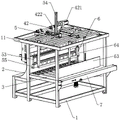
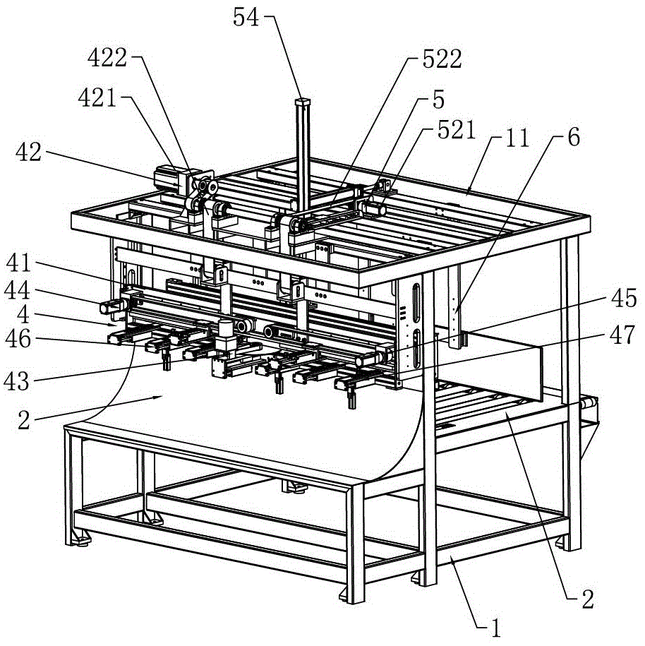
图1为本发明的结构示意图。Fig. 1 is a structural schematic diagram of the present invention.
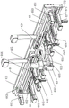
图2为本发明另一视角的结构示意图。Fig. 2 is a structural schematic diagram of another perspective of the present invention.
图3为本发明又一视角的结构示意图。Fig. 3 is a structural schematic diagram of another viewing angle of the present invention.
图4为本发明的软抽纸分离组件的结构示意图。Fig. 4 is a schematic structural view of the soft paper separation assembly of the present invention.
在图1至图4中包括有:In Figures 1 to 4 include:
1——机架 11——顶部支撑架1——
2——弧形导送板 3——承接台板2——
4——软抽纸分离组件 41——分离升降活动架4——soft pumping
42——分离升降驱动机构 421——分离升降驱动电机42——Separate
422——分离升降同步带传动机构 43——旋转分离机构422——Separation lifting synchronous
431——旋转分离安装座 432——旋转分离进给座431——rotation
433——旋转分离进给气缸 434——旋转分离转盘433——Rotary
435——旋转分离驱动电机 44——左侧活动分离机构435——Rotary
441——左侧分离驱动电机 442——左侧分离活动座441——Left
443——左侧同步带传动机构 444——左侧分离进给气缸443——Left synchronous
445——左侧分离插板 45——右侧活动分离机构445——
451——右侧分离驱动电机 452——右侧分离活动座451——right
453——右侧同步带传动机构 454——右侧分离进给气缸453——Right synchronous
455——右侧分离插板 46——左侧分离支承机构455——
461——左侧分离支承气缸 462——左侧分离支承板461——Left separated
47——右侧分离支承机构 471——右侧分离支承气缸47——Separate support mechanism on the
472——右侧分离支承板 5——自动承接组件472——Separation support plate on the
51——承接水平活动架 52——承接水平驱动机构51——Horizontal
521——承接水平驱动电机 522——承接水平同步带传动机构521——undertake
53——承接升降活动架 54——承接升降驱动气缸53——Undertake the lifting
55——活动承接板 6——自动推送组件55——movable receiving
61——推送水平活动架 62——水平推送气缸61——Push horizontal
63——活动推送板 64——升降推送气缸63——
7——水平输送带。7—Horizontal conveyor belt.
具体实施方式detailed description
下面结合具体的实施方式来对本发明进行说明。The present invention will be described below in conjunction with specific embodiments.
如图1至图4所示,一种新式软抽纸自动分叠机,包括有机架1,机架1装设有呈90度圆弧形的弧形导送板2、位于弧形导送板2后端侧且呈水平横向布置的承接台板3,机架1的上端部于承接台板3的正上方装设有顶部支撑架11,顶部支撑架11的前端部于弧形导送板2的上端侧装设有软抽纸分离组件4,顶部支撑架11于软抽纸分离组件4的后端侧装设有自动承接组件5、位于自动承接组件5后端侧的自动推送组件6,机架1于承接台板3的后端侧装设有水平输送带7。As shown in Figures 1 to 4, a new type of soft paper automatic stacking machine includes a
进一步的,软抽纸分离组件4包括有可相对上下活动地装设于顶部支撑架11前端部的分离升降活动架41,顶部支撑架11的前端部于分离升降活动架41的上端侧装设有分离升降驱动机构42,分离升降驱动机构42与分离升降活动架41驱动连接,分离升降活动架41的中间位置装设有旋转分离机构43,旋转分离机构43包括有螺装于分离升降活动架41中间位置的旋转分离安装座431,旋转分离安装座431可相对前后活动地装设有旋转分离进给座432,旋转分离安装座431对应旋转分离进给座432装设有旋转分离进给气缸433,旋转分离进给气缸433的活塞杆外延端部与旋转分离进给座432连接,旋转分离进给座432的前端部可相对转动地装设有呈圆盘形状的旋转分离转盘434,旋转分离进给座432的后端部于旋转分离转盘434的后端侧装设有旋转分离驱动电机435,旋转分离驱动电机435的动力输出轴与旋转分离转盘434驱动连接。Further, the soft
更进一步的,分离升降活动架41于旋转分离机构43的左端侧装设有左侧活动分离机构44,分离升降活动架41于旋转分离机构43的右端侧装设有右侧活动分离机构45;左侧活动分离机构44包括有装设于分离升降活动架41的左侧分离驱动电机441、左侧分离活动座442以及水平布置的左侧同步带传动机构443,左侧分离驱动电机441的动力输出轴与左侧同步带传动机构443驱动连接,左侧分离活动座442通过卡紧块紧固于左侧同步带传动机构443的传动同步带,左侧分离活动座442装设有左侧分离进给气缸444,左侧分离进给气缸444的活塞杆外延端部装设有左侧分离插板445;右侧活动分离机构45包括有装设于分离升降活动架41的右侧分离驱动电机451、右侧分离活动座452以及水平布置的右侧同步带传动机构453,右侧分离驱动电机451的动力输出轴与右侧同步带传动机构453驱动连接,右侧分离活动座452通过卡紧块紧固于右侧同步带传动机构453的传动同步带,右侧分离活动座452装设有右侧分离进给气缸454,右侧分离进给气缸454的活塞杆外延端部装设有右侧分离插板455。Furthermore, the separation lifting
另外,分离升降活动架41于左侧活动分离机构44的下端侧装设有左侧分离支承机构46,分离升降活动架41于右侧活动分离机构45的下端侧装设有右侧分离支承机构47;左侧分离支承机构46包括有至少两个左右间隔布置且分别装设于分离升降活动架41的左侧分离支承气缸461,各左侧分离支承气缸461的活塞杆外延端部分别装设有左侧分离支承板462;右侧分离支承机构47包括有至少两个左右间隔布置且分别装设于分离升降活动架41的右侧分离支承气缸471,各右侧分离支承气缸471的活塞杆外延端部分别装设有右侧分离支承板472。In addition, the separation lifting
需进一步解释,分离升降驱动机构42包括有装设于顶部支撑架11前端部的分离升降驱动电机421、呈竖向布置的分离升降同步带传动机构422,分离升降驱动电机421的动力输出轴与分离升降同步带传动机构422驱动连接,分离升降活动架41通过卡紧块紧固于分离升降同步带传动机构422的传动同步带。Further explanation is needed, the separation lifting
在本发明工作过程中,高速打纸机将软抽纸连续地送入至弧形导送板2,由于弧形导送板2呈90度圆弧形状,水平送入的软抽纸经弧形导送板2引导后会竖直朝上送出。In the working process of the present invention, the high-speed paper machine continuously feeds the soft paper to the arc-shaped
工作时,当需要将连续的软抽纸分离时,分离升降驱动电机421正转并驱动分离升降同步带传动机构422动作,分离升降同步带传动机构422通过其传动同步带带动分离升降活动架41朝下移动,以使得分离升降活动架41下移至软抽纸分离位置;待分离升降活动架41下移到位后,旋转分离驱动电机435驱动旋转分离转盘434转动,且旋转分离进给气缸433驱动旋转分离进给座432朝软抽纸侧移动,旋转分离进给座432带动旋转分离驱动电机435、旋转分离转盘434同步朝软抽纸侧移动并最终使得旋转分离转盘434旋入至连续的软抽纸内;待旋转分离转盘434旋入到位后,左侧分离驱动电机441通过左侧同步带传动机构443驱动左侧分离活动座442朝左侧移动,同时幼儿分离驱动电机通过右侧同步带传动机构453驱动右侧分离活动座452朝右侧移动,在左侧分离活动座442、右侧分离活动座452移动之前,左侧分离进给气缸444驱动左侧分离插板445插入至由旋转分离转盘434所产生的间隙内,右侧分离进给气缸454驱动右侧分离插板455插入至由旋转分离转盘434所产生的间隙内;在左侧分离驱动电机441通过左侧同步带传动机构443驱动左侧分离插板445朝左侧移动的过程中,左侧分离支承机构46的各左侧分离支承气缸461分别通过相应的左侧分离支承板462依次插入至由左侧分离插板445所产生的间隙内,同样的,在右侧分离驱动电机451通过右侧同步带传动机构453驱动右侧分离插板455朝右侧移动的过程中,右侧分离支承机构47的各右侧分离支承气缸471分别通过相应的右侧分离支承板472依次插入至由右侧分离插板455所产生的间隙内,各左侧分离支承板462以及各右侧分离支承板472支承被分离的软抽纸;待软抽纸被分离后,分离升降驱动电机421反转并通过分离升降同步带传动机构422带动分离升降活动架41朝上移动,分离升降活动架41带动已分离的软抽纸朝上移动;待已分离的软抽纸上移到位后,自动承接组件5动作并自动承接被上移抬起的软抽纸,且自动承接组件5将分离后的软抽纸自动地放置于承接台板3上表面,而后自动推送组件6动作并将放置于承接台板3上表面的软抽纸自动推送至水平输送带7,水平输送带7将软抽纸送入至相应的裁切装置中进行后续加工。During work, when the continuous soft paper needs to be separated, the separation lifting driving motor 421 rotates forward and drives the separation lifting synchronous belt transmission mechanism 422, and the separation lifting synchronous belt transmission mechanism 422 drives the separation lifting movable frame 41 through its transmission timing belt Move downwards so that the separation and lifting movable frame 41 moves down to the soft paper separation position; after the separation and lifting movable frame 41 moves down to the position, the rotary separation drive motor 435 drives the rotary separation turntable 434 to rotate, and the rotary separation feed cylinder 433 Drive the rotary separation feed seat 432 to move toward the soft paper pumping side, the rotary separation feed seat 432 drives the rotary separation drive motor 435, and the rotary separation turntable 434 moves synchronously toward the soft paper pumping side, and finally makes the rotary separation turntable 434 screw into the continuous Inside the soft pumping paper; after the rotary separation turntable 434 is screwed in place, the left separation drive motor 441 drives the left separation movable seat 442 to move to the left through the left synchronous belt transmission mechanism 443, and at the same time, the child separation drive motor drives the left side through the right synchronous The belt transmission mechanism 453 drives the right side separation movable seat 452 to move toward the right side, and before the left side separation movable seat 442 and the right side separation movable seat 452 move, the left side separation feeding cylinder 444 drives the left side separation plate 445 to be inserted into the In the gap generated by rotating the separation turntable 434, the right separation feed cylinder 454 drives the right separation insert plate 455 to insert into the gap generated by the rotation separation turntable 434; the left separation drive motor 441 is driven by the left synchronous belt During the process that the mechanism 443 drives the left separation board 445 to move to the left, each left separation support cylinder 461 of the left separation support mechanism 46 is respectively inserted into the left separation board 462 through the corresponding left separation support plate 462 to the left side separation board. In the gap produced by 445, similarly, in the process that the right side
综合上述情况可知,通过上述结构设计,本发明能够自动且高效地完成软抽纸分叠作业,即本发明具有结构设计新颖、自动化程度高、工作效率高且能够有效地节省人工成本的优点。Based on the above situation, it can be seen that, through the above structural design, the present invention can automatically and efficiently complete the soft pumping and stacking operation, that is, the present invention has the advantages of novel structural design, high degree of automation, high work efficiency and effective labor cost savings.
作为优选的实施方式,如图1至图3所示,自动承接组件5包括有可相对前后水平活动地装设于顶部支撑架11上端部的承接水平活动架51,顶部支撑架11对应承接水平活动架51装设有承接水平驱动机构52,承接水平驱动机构52与承接水平活动架51驱动连接,承接水平活动架51的下端侧可相对上下活动地装设有承接升降活动架53,承接水平活动架51对应承接升降活动架53装设有承接升降驱动气缸54,承接升降活动架53与承接升降驱动气缸54的活塞杆外延端部连接,承接升降活动架53的下端部装设有活动承接板55。As a preferred embodiment, as shown in Figures 1 to 3, the
其中,承接水平驱动机构52包括有装设于顶部支撑架11上端部的承接水平驱动电机521、沿着前后方向水平延伸的承接水平同步带传动机构522,承接水平驱动电机521的动力输出轴与承接水平同步带传动机构522驱动连接,承接水平活动架51通过卡紧块紧固于承接水平同步带传动机构522的传动同步带。Wherein, the receiving
在本发明利用自动承接组件5将已分离的软抽纸移送至承接台板3上表面时,承接水平驱动电机521通过承接水平同步带传动机构522驱动承接水平活动架51朝前移动,且承接水平活动架51带动承接升降活动架53、承接升降驱动气缸54、活动承接板55朝前移动并使得活动承接板55移动至软抽纸下方,而后承接升降驱动气缸54动作并驱动活动承接板55朝上移动,上移的活动承接板55承接由左侧分离支承板462、右侧分离支承板472所支承的软抽纸,而后承接水平驱动电机521反转并使得活动承接板55带动软抽纸朝后侧移动;待软抽纸后移到位后,承接升降驱动气缸54驱动活动承接板55下移,下移的活动承接板55最终使得软抽纸放置于承接台板3的上表面。When the present invention utilizes the
作为优选的实施方式,如图1至图3所示,自动推送组件6包括有可相对前后水平活动地装设于顶部支撑架11的推送水平活动架61,顶部支撑架11对应推送水平活动架61装设有前后动作的水平推送气缸62,水平推送气缸62的活塞杆外延端部与推送水平活动架61连接,推送水平活动架61的下端侧可相对上下活动地装设有活动推送板63,推送水平活动架61对应活动推送板63装设有升降推送气缸64,升降推送气缸64的活塞杆外延端部与活动推送板63连接。As a preferred embodiment, as shown in Figures 1 to 3, the
在自动推送组件6将承接台板3上表面的软抽纸推送至水平输送带7的过程中,升降推送气缸64先驱动活动推送板63下移,而后水平推送气缸62驱动推送水平活动架61朝后侧移动,后移的推送水平活动架61带动升降推送气缸64、活动推送板63同步朝后侧移动,后移的活动推送板63将软抽纸推送至水平输送带7。During the process of the automatic pushing
以上内容仅为本发明的较佳实施例,对于本领域的普通技术人员,依据本发明的思想,在具体实施方式及应用范围上均会有改变之处,本说明书内容不应理解为对本发明的限制。The above content is only a preferred embodiment of the present invention. For those of ordinary skill in the art, according to the idea of the present invention, there will be changes in the specific implementation and application scope. limits.
Claims (1)
Priority Applications (1)
| Application Number | Priority Date | Filing Date | Title |
|---|---|---|---|
| CN201710088544.1A CN106743921B (en) | 2017-02-20 | 2017-02-20 | Novel automatic soft tissue stacking machine |
Applications Claiming Priority (1)
| Application Number | Priority Date | Filing Date | Title |
|---|---|---|---|
| CN201710088544.1A CN106743921B (en) | 2017-02-20 | 2017-02-20 | Novel automatic soft tissue stacking machine |
Publications (2)
| Publication Number | Publication Date |
|---|---|
| CN106743921A CN106743921A (en) | 2017-05-31 |
| CN106743921B true CN106743921B (en) | 2022-12-06 |
Family
ID=58957685
Family Applications (1)
| Application Number | Title | Priority Date | Filing Date |
|---|---|---|---|
| CN201710088544.1A Expired - Fee Related CN106743921B (en) | 2017-02-20 | 2017-02-20 | Novel automatic soft tissue stacking machine |
Country Status (1)
| Country | Link |
|---|---|
| CN (1) | CN106743921B (en) |
Families Citing this family (1)
| Publication number | Priority date | Publication date | Assignee | Title |
|---|---|---|---|---|
| CN108455325A (en) * | 2018-01-29 | 2018-08-28 | 山东精诺机械股份有限公司 | A kind of full-automatic face tissue separation machine |
Family Cites Families (6)
| Publication number | Priority date | Publication date | Assignee | Title |
|---|---|---|---|---|
| IT1252779B (en) * | 1991-07-23 | 1995-06-28 | Perini Fabio Spa | DEVICE TO TRANSFER PACKAGES OF NAPKINS FROM A STACK POWERED BY A FOLDING MACHINE TO A CONVEYOR. |
| CN202464246U (en) * | 2012-01-16 | 2012-10-03 | 汕头市爱美高自动化设备有限公司 | Folding machine of removable facial tissues |
| CN203740738U (en) * | 2014-03-14 | 2014-07-30 | 吴兆广 | Automatic pile separatingdevice of automatic folding machine for household tissues |
| CN203998228U (en) * | 2014-08-15 | 2014-12-10 | 浙江国威印刷机械有限公司 | The defeated paper of full automaticity unloads the dual-purpose machine of paper |
| CN205131798U (en) * | 2015-08-24 | 2016-04-06 | 柳州市卓信自动化设备有限公司 | Automatic packing reason material device of soft paper extraction |
| CN207973298U (en) * | 2017-02-20 | 2018-10-16 | 王久任 | A kind of new-type soft paper automatically and separately stacking machine |
-
2017
- 2017-02-20 CN CN201710088544.1A patent/CN106743921B/en not_active Expired - Fee Related
Also Published As
| Publication number | Publication date |
|---|---|
| CN106743921A (en) | 2017-05-31 |
Similar Documents
| Publication | Publication Date | Title |
|---|---|---|
| CN203282151U (en) | Automation riveting machine of cooling fin fixing feet | |
| CN204369246U (en) | A kind of isarithmic paper feeder | |
| CN110253428B (en) | Automatic feeder and intermittent conveyor for clothes hanger sander | |
| CN107322355B (en) | Pipe jacking and feeding device for full-automatic pipe sawing machine | |
| CN213351053U (en) | An aluminum profile cutting machine with a palletizing device | |
| CN204736057U (en) | Vertical combination grinding machine | |
| CN210653856U (en) | High-speed unpacking origami device | |
| CN205996526U (en) | A utility knife automatic assembly equipment | |
| CN208696577U (en) | A kind of plate cutting device | |
| CN111532508B (en) | Automatic leather shell groove pressing system | |
| CN206634747U (en) | The clear powder device of automatic sheet-feeding | |
| CN106743921A (en) | A kind of new-type soft paper automatically and separately stacking machine | |
| CN210791329U (en) | Automatic feeding system of woodworking engraving machine | |
| CN207973298U (en) | A kind of new-type soft paper automatically and separately stacking machine | |
| CN106629063A (en) | Automatic piece feeding powder cleaning device and working method thereof | |
| CN212073098U (en) | Cam-type paper feeding device | |
| CN113878247B (en) | Laser pipe cutting equipment | |
| CN214978155U (en) | Copper pipe cutting device | |
| CN117299883A (en) | A bending machine with adjustable plate processing position | |
| CN213504751U (en) | Feeding device of ultrasonic cleaning machine | |
| CN211226175U (en) | Screw rod elevator | |
| CN210061321U (en) | Paperboard cutting machine convenient for adjusting cutting interval | |
| CN212474169U (en) | Automatic grooving system for leather shells | |
| CN206982759U (en) | A kind of fish meal cutter device | |
| CN209440985U (en) | A kind of new CT P platemaking machine |
Legal Events
| Date | Code | Title | Description |
|---|---|---|---|
| PB01 | Publication | ||
| PB01 | Publication | ||
| TA01 | Transfer of patent application right | ||
| TA01 | Transfer of patent application right |
Effective date of registration: 20170608 Address after: Chang Long Cun Huang Jiang town 523750 Guangdong city of Dongguan Province Liu Dong Road No. 523 Applicant after: DONGGUAN CHENGFU INDUSTRIAL Co.,Ltd. Address before: Chang Long Cun Huang Jiang town 523750 Guangdong city of Dongguan Province Liu Dong Road No. 532 Applicant before: Wang Jiuren |
|
| TA01 | Transfer of patent application right | ||
| TA01 | Transfer of patent application right |
Effective date of registration: 20181225 Address after: 514339 Beidou Community Residence Committee Dormitory, Beidou Town, Fengshun County, Guangdong Province Applicant after: Wang Jiuren Address before: 523750 No. 523 Liudong Road, Changlong Village, Huangjiang Town, Dongguan City, Guangdong Province Applicant before: DONGGUAN CHENGFU INDUSTRIAL Co.,Ltd. |
|
| SE01 | Entry into force of request for substantive examination | ||
| SE01 | Entry into force of request for substantive examination | ||
| GR01 | Patent grant | ||
| GR01 | Patent grant | ||
| CF01 | Termination of patent right due to non-payment of annual fee | ||
| CF01 | Termination of patent right due to non-payment of annual fee |
Granted publication date: 20221206 |