CN105208931B - System and method for processing biopsy samples - Google Patents
System and method for processing biopsy samples Download PDFInfo
- Publication number
- CN105208931B CN105208931B CN201480028394.XA CN201480028394A CN105208931B CN 105208931 B CN105208931 B CN 105208931B CN 201480028394 A CN201480028394 A CN 201480028394A CN 105208931 B CN105208931 B CN 105208931B
- Authority
- CN
- China
- Prior art keywords
- image
- biopsy sample
- biopsy
- sample
- processing unit
- Prior art date
- Legal status (The legal status is an assumption and is not a legal conclusion. Google has not performed a legal analysis and makes no representation as to the accuracy of the status listed.)
- Active
Links
Images


Classifications
-
- A—HUMAN NECESSITIES
- A61—MEDICAL OR VETERINARY SCIENCE; HYGIENE
- A61B—DIAGNOSIS; SURGERY; IDENTIFICATION
- A61B10/00—Other methods or instruments for diagnosis, e.g. instruments for taking a cell sample, for biopsy, for vaccination diagnosis; Sex determination; Ovulation-period determination; Throat striking implements
- A61B10/02—Instruments for taking cell samples or for biopsy
- A61B10/04—Endoscopic instruments
-
- A—HUMAN NECESSITIES
- A61—MEDICAL OR VETERINARY SCIENCE; HYGIENE
- A61B—DIAGNOSIS; SURGERY; IDENTIFICATION
- A61B10/00—Other methods or instruments for diagnosis, e.g. instruments for taking a cell sample, for biopsy, for vaccination diagnosis; Sex determination; Ovulation-period determination; Throat striking implements
- A61B10/02—Instruments for taking cell samples or for biopsy
- A61B10/0233—Pointed or sharp biopsy instruments
- A61B10/0241—Pointed or sharp biopsy instruments for prostate
-
- A—HUMAN NECESSITIES
- A61—MEDICAL OR VETERINARY SCIENCE; HYGIENE
- A61B—DIAGNOSIS; SURGERY; IDENTIFICATION
- A61B10/00—Other methods or instruments for diagnosis, e.g. instruments for taking a cell sample, for biopsy, for vaccination diagnosis; Sex determination; Ovulation-period determination; Throat striking implements
- A61B10/02—Instruments for taking cell samples or for biopsy
- A61B10/0233—Pointed or sharp biopsy instruments
- A61B10/0266—Pointed or sharp biopsy instruments means for severing sample
- A61B10/0275—Pointed or sharp biopsy instruments means for severing sample with sample notch, e.g. on the side of inner stylet
-
- A—HUMAN NECESSITIES
- A61—MEDICAL OR VETERINARY SCIENCE; HYGIENE
- A61B—DIAGNOSIS; SURGERY; IDENTIFICATION
- A61B8/00—Diagnosis using ultrasonic, sonic or infrasonic waves
- A61B8/08—Detecting organic movements or changes, e.g. tumours, cysts, swellings
- A61B8/0833—Detecting organic movements or changes, e.g. tumours, cysts, swellings involving detecting or locating foreign bodies or organic structures
- A61B8/0841—Detecting organic movements or changes, e.g. tumours, cysts, swellings involving detecting or locating foreign bodies or organic structures for locating instruments
-
- A—HUMAN NECESSITIES
- A61—MEDICAL OR VETERINARY SCIENCE; HYGIENE
- A61B—DIAGNOSIS; SURGERY; IDENTIFICATION
- A61B8/00—Diagnosis using ultrasonic, sonic or infrasonic waves
- A61B8/12—Diagnosis using ultrasonic, sonic or infrasonic waves in body cavities or body tracts, e.g. by using catheters
-
- A—HUMAN NECESSITIES
- A61—MEDICAL OR VETERINARY SCIENCE; HYGIENE
- A61B—DIAGNOSIS; SURGERY; IDENTIFICATION
- A61B8/00—Diagnosis using ultrasonic, sonic or infrasonic waves
- A61B8/42—Details of probe positioning or probe attachment to the patient
- A61B8/4245—Details of probe positioning or probe attachment to the patient involving determining the position of the probe, e.g. with respect to an external reference frame or to the patient
- A61B8/4254—Details of probe positioning or probe attachment to the patient involving determining the position of the probe, e.g. with respect to an external reference frame or to the patient using sensors mounted on the probe
-
- A—HUMAN NECESSITIES
- A61—MEDICAL OR VETERINARY SCIENCE; HYGIENE
- A61B—DIAGNOSIS; SURGERY; IDENTIFICATION
- A61B90/00—Instruments, implements or accessories specially adapted for surgery or diagnosis and not covered by any of the groups A61B1/00 - A61B50/00, e.g. for luxation treatment or for protecting wound edges
- A61B90/10—Instruments, implements or accessories specially adapted for surgery or diagnosis and not covered by any of the groups A61B1/00 - A61B50/00, e.g. for luxation treatment or for protecting wound edges for stereotaxic surgery, e.g. frame-based stereotaxis
- A61B90/11—Instruments, implements or accessories specially adapted for surgery or diagnosis and not covered by any of the groups A61B1/00 - A61B50/00, e.g. for luxation treatment or for protecting wound edges for stereotaxic surgery, e.g. frame-based stereotaxis with guides for needles or instruments, e.g. arcuate slides or ball joints
- A61B90/13—Instruments, implements or accessories specially adapted for surgery or diagnosis and not covered by any of the groups A61B1/00 - A61B50/00, e.g. for luxation treatment or for protecting wound edges for stereotaxic surgery, e.g. frame-based stereotaxis with guides for needles or instruments, e.g. arcuate slides or ball joints guided by light, e.g. laser pointers
-
- A—HUMAN NECESSITIES
- A61—MEDICAL OR VETERINARY SCIENCE; HYGIENE
- A61B—DIAGNOSIS; SURGERY; IDENTIFICATION
- A61B90/00—Instruments, implements or accessories specially adapted for surgery or diagnosis and not covered by any of the groups A61B1/00 - A61B50/00, e.g. for luxation treatment or for protecting wound edges
- A61B90/50—Supports for surgical instruments, e.g. articulated arms
-
- G—PHYSICS
- G06—COMPUTING; CALCULATING OR COUNTING
- G06T—IMAGE DATA PROCESSING OR GENERATION, IN GENERAL
- G06T7/00—Image analysis
- G06T7/0002—Inspection of images, e.g. flaw detection
- G06T7/0012—Biomedical image inspection
- G06T7/0014—Biomedical image inspection using an image reference approach
-
- A—HUMAN NECESSITIES
- A61—MEDICAL OR VETERINARY SCIENCE; HYGIENE
- A61B—DIAGNOSIS; SURGERY; IDENTIFICATION
- A61B10/00—Other methods or instruments for diagnosis, e.g. instruments for taking a cell sample, for biopsy, for vaccination diagnosis; Sex determination; Ovulation-period determination; Throat striking implements
- A61B10/02—Instruments for taking cell samples or for biopsy
- A61B10/04—Endoscopic instruments
- A61B2010/045—Needles
-
- A—HUMAN NECESSITIES
- A61—MEDICAL OR VETERINARY SCIENCE; HYGIENE
- A61B—DIAGNOSIS; SURGERY; IDENTIFICATION
- A61B34/00—Computer-aided surgery; Manipulators or robots specially adapted for use in surgery
- A61B34/10—Computer-aided planning, simulation or modelling of surgical operations
- A61B2034/101—Computer-aided simulation of surgical operations
- A61B2034/105—Modelling of the patient, e.g. for ligaments or bones
-
- A—HUMAN NECESSITIES
- A61—MEDICAL OR VETERINARY SCIENCE; HYGIENE
- A61B—DIAGNOSIS; SURGERY; IDENTIFICATION
- A61B34/00—Computer-aided surgery; Manipulators or robots specially adapted for use in surgery
- A61B34/10—Computer-aided planning, simulation or modelling of surgical operations
- A61B2034/107—Visualisation of planned trajectories or target regions
-
- A—HUMAN NECESSITIES
- A61—MEDICAL OR VETERINARY SCIENCE; HYGIENE
- A61B—DIAGNOSIS; SURGERY; IDENTIFICATION
- A61B34/00—Computer-aided surgery; Manipulators or robots specially adapted for use in surgery
- A61B34/20—Surgical navigation systems; Devices for tracking or guiding surgical instruments, e.g. for frameless stereotaxis
- A61B2034/2046—Tracking techniques
- A61B2034/2055—Optical tracking systems
- A61B2034/2057—Details of tracking cameras
-
- A—HUMAN NECESSITIES
- A61—MEDICAL OR VETERINARY SCIENCE; HYGIENE
- A61B—DIAGNOSIS; SURGERY; IDENTIFICATION
- A61B34/00—Computer-aided surgery; Manipulators or robots specially adapted for use in surgery
- A61B34/20—Surgical navigation systems; Devices for tracking or guiding surgical instruments, e.g. for frameless stereotaxis
- A61B2034/2046—Tracking techniques
- A61B2034/2063—Acoustic tracking systems, e.g. using ultrasound
-
- A—HUMAN NECESSITIES
- A61—MEDICAL OR VETERINARY SCIENCE; HYGIENE
- A61B—DIAGNOSIS; SURGERY; IDENTIFICATION
- A61B34/00—Computer-aided surgery; Manipulators or robots specially adapted for use in surgery
- A61B34/20—Surgical navigation systems; Devices for tracking or guiding surgical instruments, e.g. for frameless stereotaxis
- A61B2034/2046—Tracking techniques
- A61B2034/2065—Tracking using image or pattern recognition
-
- A—HUMAN NECESSITIES
- A61—MEDICAL OR VETERINARY SCIENCE; HYGIENE
- A61B—DIAGNOSIS; SURGERY; IDENTIFICATION
- A61B90/00—Instruments, implements or accessories specially adapted for surgery or diagnosis and not covered by any of the groups A61B1/00 - A61B50/00, e.g. for luxation treatment or for protecting wound edges
- A61B90/36—Image-producing devices or illumination devices not otherwise provided for
- A61B2090/363—Use of fiducial points
-
- A—HUMAN NECESSITIES
- A61—MEDICAL OR VETERINARY SCIENCE; HYGIENE
- A61B—DIAGNOSIS; SURGERY; IDENTIFICATION
- A61B90/00—Instruments, implements or accessories specially adapted for surgery or diagnosis and not covered by any of the groups A61B1/00 - A61B50/00, e.g. for luxation treatment or for protecting wound edges
- A61B90/36—Image-producing devices or illumination devices not otherwise provided for
- A61B2090/364—Correlation of different images or relation of image positions in respect to the body
- A61B2090/367—Correlation of different images or relation of image positions in respect to the body creating a 3D dataset from 2D images using position information
-
- A—HUMAN NECESSITIES
- A61—MEDICAL OR VETERINARY SCIENCE; HYGIENE
- A61B—DIAGNOSIS; SURGERY; IDENTIFICATION
- A61B90/00—Instruments, implements or accessories specially adapted for surgery or diagnosis and not covered by any of the groups A61B1/00 - A61B50/00, e.g. for luxation treatment or for protecting wound edges
- A61B90/36—Image-producing devices or illumination devices not otherwise provided for
- A61B90/37—Surgical systems with images on a monitor during operation
- A61B2090/374—NMR or MRI
-
- A—HUMAN NECESSITIES
- A61—MEDICAL OR VETERINARY SCIENCE; HYGIENE
- A61B—DIAGNOSIS; SURGERY; IDENTIFICATION
- A61B90/00—Instruments, implements or accessories specially adapted for surgery or diagnosis and not covered by any of the groups A61B1/00 - A61B50/00, e.g. for luxation treatment or for protecting wound edges
- A61B90/36—Image-producing devices or illumination devices not otherwise provided for
- A61B90/37—Surgical systems with images on a monitor during operation
- A61B2090/376—Surgical systems with images on a monitor during operation using X-rays, e.g. fluoroscopy
-
- A—HUMAN NECESSITIES
- A61—MEDICAL OR VETERINARY SCIENCE; HYGIENE
- A61B—DIAGNOSIS; SURGERY; IDENTIFICATION
- A61B90/00—Instruments, implements or accessories specially adapted for surgery or diagnosis and not covered by any of the groups A61B1/00 - A61B50/00, e.g. for luxation treatment or for protecting wound edges
- A61B90/36—Image-producing devices or illumination devices not otherwise provided for
- A61B90/37—Surgical systems with images on a monitor during operation
- A61B2090/378—Surgical systems with images on a monitor during operation using ultrasound
- A61B2090/3782—Surgical systems with images on a monitor during operation using ultrasound transmitter or receiver in catheter or minimal invasive instrument
-
- A—HUMAN NECESSITIES
- A61—MEDICAL OR VETERINARY SCIENCE; HYGIENE
- A61B—DIAGNOSIS; SURGERY; IDENTIFICATION
- A61B90/00—Instruments, implements or accessories specially adapted for surgery or diagnosis and not covered by any of the groups A61B1/00 - A61B50/00, e.g. for luxation treatment or for protecting wound edges
- A61B90/39—Markers, e.g. radio-opaque or breast lesions markers
- A61B2090/3983—Reference marker arrangements for use with image guided surgery
-
- A—HUMAN NECESSITIES
- A61—MEDICAL OR VETERINARY SCIENCE; HYGIENE
- A61B—DIAGNOSIS; SURGERY; IDENTIFICATION
- A61B2576/00—Medical imaging apparatus involving image processing or analysis
-
- A—HUMAN NECESSITIES
- A61—MEDICAL OR VETERINARY SCIENCE; HYGIENE
- A61B—DIAGNOSIS; SURGERY; IDENTIFICATION
- A61B5/00—Measuring for diagnostic purposes; Identification of persons
- A61B5/05—Detecting, measuring or recording for diagnosis by means of electric currents or magnetic fields; Measuring using microwaves or radio waves
- A61B5/055—Detecting, measuring or recording for diagnosis by means of electric currents or magnetic fields; Measuring using microwaves or radio waves involving electronic [EMR] or nuclear [NMR] magnetic resonance, e.g. magnetic resonance imaging
-
- G—PHYSICS
- G06—COMPUTING; CALCULATING OR COUNTING
- G06T—IMAGE DATA PROCESSING OR GENERATION, IN GENERAL
- G06T2207/00—Indexing scheme for image analysis or image enhancement
- G06T2207/10—Image acquisition modality
- G06T2207/10056—Microscopic image
-
- G—PHYSICS
- G06—COMPUTING; CALCULATING OR COUNTING
- G06T—IMAGE DATA PROCESSING OR GENERATION, IN GENERAL
- G06T2207/00—Indexing scheme for image analysis or image enhancement
- G06T2207/30—Subject of image; Context of image processing
- G06T2207/30004—Biomedical image processing
- G06T2207/30024—Cell structures in vitro; Tissue sections in vitro
Abstract
A system for facilitating obtaining a biopsy sample from a body of a patient is provided that includes a display for displaying an image to a user. The system further comprises a processing unit functionally associated with the display, wherein the processing unit comprises an image processing module. The system further includes a camera functionally associated with the processing unit via a communication channel for communicating images from the camera to the processing unit and configured to obtain an image of a biopsy sample from a patient's body. The processing unit is configured to receive image data from an imaging modality capable of obtaining images of internal body parts not directly visible from outside the patient's body, and to display images related to the image data on the display for the user. The processing unit is further configured to generate a processed image related to the biopsy sample from the at least one image of the biopsy sample and using the image processing module, and to display the processed image on the display.
Description
Technical Field
In some embodiments, the present invention relates to the field of biopsy samples, and more particularly, but not exclusively, to systems and methods for obtaining biopsy samples and manipulating and processing such biopsy samples.
Background
Biopsy is a routine procedure for obtaining samples of biological tissue from a living organ for laboratory testing. Typically, the surgeon is assisted by a support system when performing such a procedure. For example, a biopsy sample may be obtained from an internal organ of the body that is not visible from outside the body and is therefore not directly visible to the surgeon. In this case, an imaging instrument like an ultrasound, MRI or X-ray system may be used to provide the surgeon with an image of the region inside the body from which the biopsy sample is to be obtained. In some cases, such images may also be used to identify sites that are suspected of being abnormal and thus are candidates for obtaining a biopsy sample therefrom. In some cases, such images, especially if provided to the surgeon continuously in a real-time video stream, may image the surgeon the organ or the border line of the organ, and may also image the biopsy needle as it is advanced towards the desired biopsy site.
The tracking system may also be used to provide the surgeon with a substantially continuous stream of position data for the treatment tool, thereby facilitating navigation of the treatment tool to the desired location. In addition, the position data of a portable imaging modality, such as an ultrasound portable imaging probe, provided by such a tracking system may be utilized to assign image position data to the image data obtained by the imaging modality, for example by assigning a position along a predetermined coordinate system for substantially each pixel in each image.
International patent application publication No. WO/2011/161684 (hereinafter named '684), filed on 23/6/2011, and international patent application No. PCT/IL2013/050065 (hereinafter named' 065), filed on 24/1/2013, both of which are incorporated herein by reference, describe various embodiments that incorporate an integrated system of data from a tracking system and from an imaging instrument to facilitate a treatment procedure. In particular, in some embodiments, such systems may facilitate obtaining a biopsy sample from a desired site in an internal organ that is not directly visible from outside the body. According to some embodiments, a series of two-dimensional (2D) images of an organ, such as a prostate of a male, are obtained, and each image is assigned image location data as described above. A set of substantially parallel images obtained with a sufficiently small spatial separation between each other may be suitably arranged and combined to obtain a three-dimensional (3D) image of the imaged organ. Furthermore, a virtual 3D model of the imaged organ may be generated and stored in the memory of the computer by identifying the boundary line of the imaged organ, for example by computerized image recognition or by manual inspection of the image and virtually marking the boundary line of the imaged organ.
By continuously tracking the position of the treatment tool, and further by identifying the time of a particular treatment event, the location of the treatment site to which the treatment was actually applied, may be recorded with a predetermined 3D coordinate system, e.g. a predetermined coordinate system associated with the tracking system. For example, by continuously tracking the position of the biopsy needle with the tracking system as described above, the position of the needle relative to the position of the target organ from which the biopsy is to be obtained may be continuously recorded. By recording the moment at which the biopsy sample is obtained, the exact location from which the biopsy sample is obtained can be recorded using a 3D coordinate system. In some embodiments, the location from which the biopsy sample was obtained may thus be marked on the virtual 3D model of the organ, and may later be used to navigate the treatment tool to the same site.
Disclosure of Invention
In some embodiments of the invention, aspects of the invention relate to systems and methods for obtaining biopsy samples and manipulating and processing such biopsy samples. More specifically, in some embodiments of the invention, aspects of the invention relate to systems and methods for imaging obtained biopsy samples.
As discussed above, current systems, particularly those that include imaging instruments and/or tracking systems, may assist a surgeon in navigating a treatment tool to a treatment site that is not directly visible to the surgeon during a treatment procedure. One or more techniques may be used to provide this assistance. For example, by presenting the surgeon with the positioning of the treatment tool and the target location to be treated relative to the same reference frame (e.g., the same 3D coordinate system) in substantially real time, the surgeon is provided with feedback of the relative distance and direction between the treatment tool and the treatment site, thereby assisting the surgeon in navigating the treatment tool to the desired treatment site. As another example, the treatment tool, or a synthetic marker indicating the positioning of the treatment tool, may be displayed on the screen in real time together with an image of the organ to be treated or a virtual 3D model of the organ, positioned on the screen according to the real 3D position of the organ in the body, as this position is revealed, for example, from the image of the organ. By displaying the real-time positioning of the treatment tool and the treatment site on the same screen, the surgeon is provided with feedback on the relative distance and orientation between the treatment tool and the treatment site.
Enhancing the real-time feedback provided to the surgeon during the procedure can further simplify the procedure and improve its quality. In particular, providing the surgeon with an image of the obtained biopsy sample may significantly improve the surgeon's decision regarding the location from which the next sample will be obtained and regarding the number of samples still to be obtained from the organ within the current biopsy session. For example, an obtained image of a biopsy sample may indicate to the surgeon that the sample is truncated, fragmented, or broken, resulting in a decision to obtain the next sample from substantially the same site to avoid reducing the probability of detection. Additionally, the image of the biopsy sample may be stored in computer memory for later use or examination. Further, by utilizing image processing and image recognition techniques on an image of a biopsy sample, spatial features, such as the length of the sample, may be automatically obtained.
When employing a system that is capable of presenting a virtual 3D model of the organ under examination to the surgeon in real time and during the biopsy period, and that is also capable of adding to the model a synthetic marker indicating the location from which the biopsy sample was obtained, the actual length of the imaged sample may be displayed graphically by displaying a synthetic marker whose length is proportional to the length of the imaged sample. Furthermore, by imaging the biopsy sample on the biopsy needle, the exact location of the sample on the biopsy needle may be measured. For example, the location of the sample on the notch of the biopsy needle may be detected or the distance of the sample from a landmark of the biopsy needle (such as the distal tip) may be measured. Such measurement of distance may be accomplished automatically, for example using image recognition techniques, or manually by a user, or by any combination thereof.
When a system incorporating an imaging instrument and/or tracking system as described above is employed, and further when the instantaneous position of the biopsy needle is registered with the 3D coordinate system at the moment of taking the biopsy sample, the exact location of the site from which the sample was obtained can be registered. This accurate localization can then be displayed in real time for the surgeon, e.g. on a virtual 3D model of the organ, so that the surgeon can decide the position in the examined organ from which the next biopsy sample should be obtained. This accurate positioning may further be stored for later use, for example, when the surgeon considers obtaining more biopsy samples or when the surgeon considers applying local and focused treatment to a particular treatment site, displayed on the virtual 3D model of the organ at the next treatment session.
Thus, according to an aspect of some embodiments, there is provided a system for facilitating obtaining a biopsy sample from a body of a patient, comprising a display for displaying an image to a user. The system also includes a processing unit functionally associated with the display, wherein the processing unit includes an image processing module. The system further includes a camera functionally associated with the processing unit for transmitting images from the camera to the processing unit and configured to obtain images of a biopsy sample obtained from a body of a patient. The processing unit is configured to receive image data from an imaging modality capable of obtaining images of internal body parts not directly visible from outside the patient's body and to display images related to the image data to a user on a display. The processing unit is further configured to generate a processed image related to the biopsy sample from at least one image in the biopsy sample and using the image processing module, and to display the processed image on the display.
According to some embodiments, the imaging modality includes an ultrasonography module capable of obtaining an ultrasound image of the internal body part. According to some embodiments, the imaging modality includes a Magnetic Resonance Imaging (MRI) module capable of obtaining MRI images of the internal body part. According to some embodiments, the imaging modality comprises an X-ray imaging module capable of obtaining X-ray images of the internal body part.
According to some embodiments, the image processing module is configured to generate a map of the biopsy sample from an image of the biopsy sample received from the camera. According to some embodiments, the image processing module is configured to identify a boundary of the biopsy sample on the image of the biopsy sample received from the camera. According to some embodiments, the image processing module is configured to generate, from the image of the biopsy sample, a contour substantially delineating a boundary of the biopsy sample on the image. According to some embodiments, the image processing module is configured to generate a plurality of individual contours from an image of a biopsy sample fragmented into pieces, wherein each such contour substantially delineates a boundary of a piece of the biopsy sample on the image.
Current methods for manipulating and processing biopsy samples may include the step of verifying the source of the biopsy sample to avoid errors while reporting laboratory test results. Examples of the inspection method include: DNA or DNA-related genetic material in the sample is identified and a DNA profile associated with the sample is compared to a profile of DNA of a person from whom the sample is believed to have been taken. For example, a sample may be obtained from a biopsy sample prior to or shortly after pathological examination (e.g., under a microscope), and the sample subjected to DNA analysis. Only if the DNA associated with the sample is found to be consistent with the DNA of the person from whom the sample is believed to have been taken, the results of the pathological test are reported to that person.
DNA analysis is an expensive test that requires extensive equipment, trained personnel, and time resources. Accordingly, there is a need for a method that facilitates verification of the source of a biopsy sample by using a simpler method to verify or verify the identity of the biopsy sample, over prior art methods.
By utilizing imaging of a biopsy sample obtained from a patient's body as described herein, verifying the origin of the biopsy sample may be accomplished. Accordingly, there is provided a method of processing a biopsy sample, comprising: providing a biopsy sample obtained from a body of a patient; obtaining a first image of a biopsy sample; a second image of the biopsy sample is obtained and image data obtained from the first image is compared to image data obtained from the second image to verify or prove the identity of the biopsy sample.
According to some embodiments, the method further comprises a step of chemically treating the biopsy sample performed after obtaining the first image and before obtaining the second image. According to some embodiments, the method further comprises the step of segmenting the biopsy sample performed after obtaining the first image and before obtaining the second image. According to some embodiments, obtaining at least one of the first image and the second image is performed using an imaging device. According to some embodiments, the imaging device is a camera. According to some embodiments, the method further comprises the step of staining the biopsy sample before performing the step of obtaining the first image of the biopsy sample.
According to some embodiments, the method further comprises processing the first image and the second image to generate a map from the image data of each image, wherein the comparing step comprises comparing a map obtained from the first image with a map obtained from the second image. According to some embodiments, the map represents topographical variations of the biopsy sample. According to some embodiments, the map represents material variations of the biopsy sample.
The present invention separately provides a system that can be used to display a processed image of a biopsy sample shortly after it is obtained from a body.
The present invention separately provides a system that can be used to display a map of a biopsy sample that represents topographical and/or material changes of the sample.
The present invention separately provides a system that can be used to provide the spatial dimensions of a biopsy sample extracted from an image of the sample.
The present invention separately provides a system that can be used to display a combined image comprising a processed image of a biopsy sample and an image of an internal body part that is not visible from outside the body.
The present invention separately provides a system that may be used to display a combined image comprising an image of an internal body part that is not visible from outside the body, or a virtual model of such an internal body part and a processed image of a biopsy sample, or a composite marker representing such a biopsy sample located on the combined image at a location in the internal body part corresponding to the location from which the biopsy sample was obtained.
The present invention separately provides a method that can be used to obtain a biopsy sample from a desired location in an internal body part that is not directly visible from the outside of the body.
The present invention separately provides a method that can be used to validate or prove the identity of a biopsy sample prior to sending test results regarding the sample to a person from whom the sample is believed to have been taken.
Certain embodiments of the invention may include all, some, or none of the above advantages. Additional advantages may be apparent to one skilled in the art from the figures, descriptions, and claims included herein. Aspects and embodiments of the invention are further described in the following description and in the appended claims.
Unless defined otherwise, all technical and scientific terms used herein have the same meaning as commonly understood by one of ordinary skill in the art to which this invention belongs. In case of conflict, the present patent specification, including definitions, will control. As used herein, the indefinite articles "a" and "an" mean "at least one" or "one or more" unless the context clearly dictates otherwise.
Embodiments of the method and/or apparatus of the present invention may involve performing or completing selected tasks manually, automatically, or in a combination thereof. Some embodiments of the invention are implemented using components comprising hardware, software, firmware or a combination thereof. In some embodiments, some of the components are general-purpose components, such as a general-purpose computer or oscilloscope. In some embodiments, some components are application-specific or custom components, such as circuits, integrated circuits, or software.
For example, in some embodiments, some of the embodiments may be implemented by a plurality of software instructions being executed by a processor, e.g., that is part of a general purpose or customized computer. In some embodiments, the processor or computer includes volatile memory and/or non-volatile storage for storing instructions and/or data, such as a magnetic hard disk and/or removable media for storing instructions and/or data. In some embodiments, the implementation includes a network connection. In some embodiments, implementations include a user interface, typically including one or more of an input device (e.g., to allow input of commands and/or parameters) and an output device (e.g., to allow reporting of parameters and results of operations).
Aspects and embodiments of the invention are described in the following description and in the appended claims.
Drawings
Some embodiments of the invention are described herein with reference to the accompanying drawings. This description, together with the drawings, makes apparent to those skilled in the art how some embodiments of the invention may be practiced. The drawings are for illustrative purposes and are not intended to show structural details of the embodiments in more detail than is necessary for a fundamental understanding of the invention. For purposes of clarity, certain objects shown in the drawings are not to scale.
In the drawings:
FIG. 1 schematically illustrates an embodiment of a system for facilitating obtaining a biopsy sample from a body of a patient;
FIG. 2A schematically shows an image of a biopsy sample obtained by the camera of FIG. 1;
FIG. 2B schematically illustrates a map generated by the image processing module of FIG. 1 representing topographical variations of the biopsy sample imaged in FIG. 2A;
FIG. 2C schematically shows a map generated by the image processing module of FIG. 1 representing material variations of the biopsy sample imaged in FIG. 2A;
FIG. 2D schematically shows an image of a biopsy sample broken into two pieces;
fig. 2E schematically shows a map of the biopsy sample generated by the image processing module of fig. 1 imaged in the image of fig. 2D.
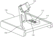
FIG. 3A schematically illustrates an embodiment of the camera of FIG. 1 attached to a mount, wherein the mount is configured to support a biopsy sample such that the camera is aimed at the biopsy sample to obtain an image thereof;
FIG. 3B schematically illustrates an embodiment of the camera of FIG. 1 attached to a mount, wherein the mount is configured to support a sample holder carrying a biopsy sample such that the camera is aimed at the biopsy sample to obtain an image thereof;
FIG. 3C schematically illustrates the embodiment shown in FIG. 3A, wherein the camera is aimed at the biopsy sample from a different direction;
FIG. 4 schematically illustrates an embodiment of a system for facilitating obtaining a biopsy sample from a body of a patient that includes the system of FIG. 1 and also includes a tracking system, according to teachings herein;
FIG. 5 schematically illustrates an embodiment of the camera of FIG. 1 or FIG. 4 configured to obtain an image of a biopsy sample supported on a biopsy needle;
FIG. 6A schematically shows an image of a biopsy sample supported on a notch of a biopsy needle obtained by the camera of FIG. 1 or FIG. 4;
FIG. 6B schematically shows a map generated from the image of FIG. 6A by an embodiment of the image processing module of FIG. 1 or FIG. 4, an
Fig. 7 schematically illustrates an embodiment of a method of processing a biopsy sample according to the teachings herein.
Detailed Description
The principles, uses and implementations of the teachings herein may be better understood with reference to the accompanying description and drawings. Upon perusal of the description and figures presented herein, one of ordinary skill in the art will be able to implement the present invention without undue effort or experimentation.
Fig. 1 schematically illustrates an embodiment of a system 100 for facilitating obtaining a biopsy sample from a body of a patient. The system 100 includes a display 102 for displaying images to a user. The system 100 also includes a processing unit 104 that is functionally associated with the display 102 and includes an image processing module 106. The system 100 also includes a camera 110 functionally associated with the processing unit 104 for transferring images from the camera to the processing unit. The camera 110 is configured to obtain images of a biopsy sample 112 obtained from a patient's body and to transmit these images to the processing unit 104 via a communication channel 114. Transferring the images from the camera to the processing unit may be done automatically in real time, meaning that each image is transferred to the processing unit 104 substantially immediately after the image is obtained. Or the images may be stored in a memory device in the camera and transmitted to the processing unit 104 when a predetermined event occurs. Such a predetermined event may be a command by the operator or any decision criteria programmed, for example, to the camera, such as obtaining a predetermined number of images, implementing an event that may trigger the transfer of images. According to some embodiments, the communication channel 114 may include a wire. According to some embodiments, the communication channel 114 may be wireless, e.g., employing radio communication.
The system 100 is configured to be functionally associated with an imaging modality 120 capable of obtaining images of internal body parts not directly visible from outside the patient's body. An example of imaging modality 120 may be an ultrasound imaging system, an MRI imaging system, or an X-ray imaging system. Imaging instrument 120 may include a portable imaging probe 122, such as an ultrasound portable imaging probe in an ultrasound imaging system. Imaging modality 120 may also include an imaging modality display 124 for displaying, for example, acquired images of an internal body part.
By employing the image processing module 106, the processing unit 104 is configured to generate a processed image related to the biopsy sample 112 from the image of the at least one biopsy sample 112 and to display the processed image on the display 102.
Fig. 2A schematically shows an image 150a of a biopsy sample obtained by the camera 110 and transferred to the processing unit 104 for image processing by the image processing module 106. The image processing module 106 is configured to generate a map of the biopsy sample from the image 150 a. Fig. 2B schematically illustrates a map 152 generated by the image processing module 106 representing topographical variations of an imaged biopsy sample, in accordance with some embodiments. In particular, contours 154a and 154b represent height variations above the surface of the sample, where contour 154a delineates the boundary of the biopsy sample on image 150 a. Identifying the boundary of the sample in the image 150a may be done automatically by the image processing module 106 using object recognition methods known in the art, or such identification may be aided by a marker or markers (e.g., numerous points marked by the user along the boundary of the sample in the image 150 a) that are actually marked on the image 150a by the user.
Fig. 2C schematically illustrates a map 156 generated by the image processing module 106 representing material changes of the biopsy sample imaged in the image 150a, according to some embodiments. Identifying material variations may be accomplished, for example, by identifying regions in image 150a having different colors or different gray levels.
Fig. 2D schematically shows an image 150b of a biopsy sample broken into two pieces. Each of the two contours 158a and 158b, respectively, generated by the image processing module 106, substantially delineate the boundary of a piece of biopsy sample on the image 150b, according to some embodiments.
According to some embodiments, the communication channel 114 may include a wire for transmitting images from the camera to the processing unit. According to some embodiments, the communication channel 114 may include a wireless communication channel for communicating images from the camera to the processing unit. According to some embodiments, the camera 110 is associated with a radio transmitter (not shown) that may, for example, be attached to or positioned in proximity to the camera, while the processing unit 104 is functionally associated with a radio receiver that may, for example, be positioned in proximity thereto. Image data obtained by the camera 110 may thus be electrically communicated to the radio transmitter, then transmitted from the radio transmitter and received by the radio receiver, and electrically communicated to the processing unit 104.
According to some embodiments, the communication channel 114 is unidirectional, configured to transmit images from the camera to the processing unit. According to some embodiments, the communication channel 114 may be bidirectional. According to some embodiments, the camera 110 is configured and functionally associated with the processing unit 104 for receiving operational commands from the processing unit 104. Thus, the user operating system 100 may activate the camera 110 through a user interface (not shown in FIG. 1) of the system 100, transmitting commands through the communication channel 114. Such user interfaces may include typical user interface devices for interfacing with a computer system, such as a keyboard, mouse, joystick, etc., as is known in the art, and/or a dedicated user interface, such as an electronic command panel including control buttons and signaling components such as lights and a screen. According to some embodiments, the camera 110 may be a still camera that provides a single image or a series of different images when activated. According to some embodiments, the camera 110 may be a video camera that, when activated, provides a video stream.
Fig. 3A and 3B schematically illustrate the camera 110 attached to a mount 116, wherein the mount 116 is configured to support the biopsy samples 112 so that the camera 110 is aimed at the biopsy samples to obtain images thereof. The cradle 116 includes a base 118 configured and aligned to support the biopsy sample 112 thereon. According to some embodiments, the mount 118 may be coated on its top surface with a non-stick material, such as polypropylene or polytetrafluoroethylene, so that the biopsy sample 112 does not stick to the mount 118. After an image of the biopsy sample is obtained by the camera 110, the biopsy sample 112 may be easily removed from the mount 118.
According to some embodiments, as schematically illustrated in fig. 3B, the base 118 may be configured to mount thereon a sample rack, such as a cartridge 126. The cartridge 126 may be configured to hold and/or carry a biopsy sample thereon, and an image of the biopsy sample may be obtained by mounting the cartridge 126 carrying the biopsy sample thereon on the mount 118 as shown in fig. 3B, and subsequently activating the camera 110. According to some embodiments, the cartridge 126 may include an adhesive surface 128 configured to adhere to a biological sample upon contact with such biological sample. Some embodiments of sample holders (e.g., cassette 126) are described in detail in international patent application publication No. WO2013105095 (herein' 095), filed on 10/1/2013, which is incorporated herein by reference in its entirety.
According to some embodiments, the bracket 116 may include a slot 136, and the camera 110 is attached to the bracket 116 over the slot 136. Camera 110 may be fixedly attached to mount 116 at a desired point along slot 136 to aim biopsy sample 112 from several directions and to acquire images of biopsy sample 112 from multiple angles.
According to some embodiments, the image processing module 106 is configured to generate a virtual 3D model of the biopsy sample 112 by processing a plurality of images of the biopsy sample respectively obtained from several directions, using methods known in the art.
According to some embodiments, the length scale 138 is positioned on or near the base 118, allowing the image of the biopsy sample to incorporate a length scale. By comparing the biopsy sample with the length scale on the image, the size of the biopsy sample, such as length or width, may be obtained. According to some methods, the size of the biopsy sample may be obtained by manually comparing the size of the image of the biopsy sample within its boundaries with the length scale, for example using a ruler. According to some embodiments, the size of the biopsy sample may be obtained automatically by the image processing module 106 using image processing and object recognition techniques. The maximum distance, measured in pixels, for example, between points on the contour of the map of the biopsy sample, such as contour 154B in fig. 2B, may be compared to the distance measured in pixels along the image of the length scale 138. Other methods and techniques as are well known in the art to establish the size of the biopsy sample imaged alongside length scale 138 are contemplated.
According to some embodiments, the processing unit 104 further comprises a 3D modeling module 108. 3D modeling module 108 is configured to receive image data provided by imaging instrument 120, where the image data is assigned corresponding image position data along preselected coordinates. Image data assigned with image position data means that substantially every pixel in an image corresponding to the image data is assigned with a localization value along a predetermined set of coordinates. The image data so designated with the image data locations may be received, for example, from an MRI imaging system, wherein the images typically correspond to well-defined planes in space. As another example, image data designated with image location data may be received from an ultrasound system having a portable imaging probe with a known location. When the position of the portable imaging probe is known, the position corresponding to the image obtained by the portable imaging probe may also be known, and image position data may therefore be assigned to such images. The 3D modeling module 108 is further configured to create a virtual 3D model of the organ using appropriately selected image data of the organ designated with image location data, such as detailed in '684 and in' 065.
Fig. 4 schematically illustrates an embodiment of a system 140 that includes the system 100 described above for facilitating obtaining a biopsy sample from a patient's body, and that also includes a tracking system 160. The tracking system 160 is functionally associated with one or more tracking sensors 162, such as tracking sensors 162a, 162b, and 162 c. According to some embodiments, each tracking sensor 162 is configured to report its position relative to a fixed point in space to the tracking system 160, and the tracking system 160 is configured to calculate and provide, substantially in real time, the location and orientation of each tracking sensor 162 along a preselected coordinate system 164. Tracking the position of a tracking sensor 162 by the tracking system 160 may employ one of several known methods and techniques, or a combination thereof. For example, according to some embodiments, each tracking sensor may be made by including a pass-through jointThe folded arms of the interconnected rigid segments are mechanically connected to a fixed point in space. A sensor measuring the fold angle of the joint may be employed to report the location in space of the tracking sensor relative to a point in space to which it is mechanically connected. According to some embodiments, each tracking sensor may be equipped with an accelerometer, and the tracking sensor may be configured to report by combining acceleration values measured by the accelerometer, such as the magnitude and direction of its displacement. According to some embodiments, tracking system 160 includes an electromagnetic field generating device (not shown) that generates an Electromagnetic (EM) field having a known magnitude and direction in substantially each point in the workspace. Each tracking sensor 162 may be configured to substantially instantaneously detect and report the magnitude and direction of the EM field substantially at the location of the tracking sensor 162, and the tracking system 160 is configured to receive such reports from each tracking sensor and translate the reports into position data along a 3D coordinate system. An example of a commercially available EM tracking system is the 3D guide trakSTAR of advanced technology corporationTM。
The tracking system 160 in fig. 4 is functionally associated with the processing unit 104 and is configured to provide position data including the location and orientation of the tracking sensor 162 along the coordinate system 164 to the processing unit 104 substantially in real time. Tracking sensor 162a is fixedly attached to portable imaging probe 122 of imaging instrument 120 so as to have a known spatial relationship with portable imaging probe 122. The processing unit 104 is configured to receive the position of the tracking sensor 162a reported by the tracking system 160 to the processing unit 104, and thereby record the position of the portable imaging probe 122. According to some embodiments, imaging instrument 120 comprises an ultrasound imaging system, and portable imaging probe 122 comprises an ultrasound portable imaging probe, such as a transrectal ultrasound probe. The portable imaging probe 122 obtains images from a region, such as a plane, in space having a known spatial relationship to the position of the portable imaging probe 122. Processing unit 104 may assign image position data received from tracking system 160 to image data received from imaging modality 120 by considering the position of portable imaging probe 122 reported by tracking system 160 and the known spatial relationship between portable imaging probe 122 and the region in space from which the portable imaging probe obtained image data.
According to some embodiments, the tracking sensor 162b may be fixedly attached to the portable treatment tool 170. The processing unit 104 is configured to receive the position of the tracking sensor 162b reported to the processing unit 104 by the tracking system 160 and thereby record, substantially in real time, the position of the portable treatment tool 170 substantially continuously.
According to some embodiments, the treatment tool 170 may include a biopsy needle 172. According to some embodiments, biopsy needle 172 may be configured to obtain a biopsy sample of, for example, a prostate.
According to some embodiments, the portable imaging probe 122 may include a needle guide (not shown) for guiding the portable treatment tool 170 (e.g., biopsy needle 172) along a predefined trajectory during treatment. For example, the portable imaging probe 122 may comprise a transrectal ultrasound probe having a needle guide suitable for insertion of a therapeutic tool, such as a biopsy needle configured to obtain a biopsy sample from the prostate. When the biopsy needle 172 is properly positioned in the needle guide of the portable imaging probe 122, the biopsy needle 172 has a known spatial relationship with portions of the tracking sensor 162 a. According to some embodiments, the processing unit 104 is configured to generate a combined image comprising the image data received from the imaging instrument 120 and the synthetic marker indicative of the location of the biopsy needle 172. The composite marker is displayed in the combined image in a location corresponding to the position of the biopsy needle 172 as reported by tracking sensor 162a or tracking sensor 162b relative to the region in space from which the image data is collected as reported by tracking sensor 162 fixed to the imaging probe 122. For example, the composite marker may include a line extending across the ultrasound image that corresponds to the direction of the needle guide in the plane of the ultrasound image. When the treatment tool 170 (e.g., biopsy needle 172) is in the needle guide, its position on the ultrasound image is partially known, known to be along the line, and the location of the needle (e.g., the tip of the needle) along the line is unknown. Using the position data of tracking sensor 162a, processing unit 104 may specify image position data to the ultrasound image, thereby specifying position data along coordinate system 164 for each pixel in the image. The drop of the treatment tool 170 is partially known, that is, the position coordinates that are constrained to the line are known.
According to some embodiments, the processing unit 104 includes a 3D modeling module 108. As described above, the image data obtained by imaging instrument 120 using portable imaging probe 122 is image position data specified by processing unit 104 from position data reported by tracking sensor 162 a. The 3D modeling module 108 is configured to receive such image data designated with corresponding image location data as also described in detail in '684 and' 065. According to some embodiments, the 3D modeling module 108 is configured to merge image data of a series of 2D images into a 3D image that includes "volumetric pixels" ("voxels"). For example, a series of substantially parallel 2D images obtained at small intervals from each other may be combined according to the image position data assigned to them to generate a single 3D image containing a volume imaged by the series of 2D images.
According to some embodiments, the 3D modeling module 108 is configured to create a virtual 3D model of the organ using appropriately selected image data of the organ specified with the image location data. According to some embodiments, the processing unit 104 is configured to generate a combined image comprising the virtual 3D model of the organ generated by the 3D modeling module 108 and the synthetic marker indicative of the positioning of the biopsy needle 172. According to some embodiments, the positioning of the synthetic markers on the combined image relative to the virtual 3D model depends on the positions reported by the tracking system 160 and received by the processing unit 104.
According to some embodiments, as described above, the image processing module 106 is configured to generate a contour from an image of the biopsy sample 112 received from the camera 110 that substantially delineates a boundary of the biopsy sample on the image. Fig. 5 schematically shows an embodiment of the camera 110 configured to obtain an image of a biopsy sample 112 supported on a biopsy needle 172. The cradle 182 includes a gun mount 184 configured to secure a biopsy gun 186 including the biopsy needle 172 therein. The base 118 supports the distal end of the biopsy needle in a horizontal line. The base 118 supports a needle bed 190 having two aligned wings 192 and an aligned support platform 194 along the centerline of the needle bed 190. Needle bed 190 may thus support biopsy needle 172 such that biopsy needle 172 is disposed between alignment wings 192 such that the notch of the biopsy needle is supported on support platform 194. Cradle 182 also includes a length scale 138 disposed on base 118 proximate support platform 194 and extending along biopsy needle 172. The camera 110 is positioned to aim at the biopsy sample 112 supported on the indentation of the biopsy needle such that the camera 110 is configured to obtain an image of the biopsy sample supported in the biopsy needle 172.
Fig. 6A schematically shows an image 200 of a biopsy sample 112 supported on a notch 208 of a biopsy needle 172 obtained by a camera 110 (not shown in this figure). A length scale 138, positioned proximate to the biopsy needle and biopsy sample, provides a length scale for the imaged item in image 200.
Fig. 6B schematically shows a map 220 generated by the image processing module 106 from the image 200 of fig. 6A. Map 220 includes a contour 222 delineating the boundary of biopsy sample 112 in image 200, and a contour 224 delineating the boundary of the distal portion of biopsy needle 172. By employing known image recognition methods and known critical dimension measurement methods, the processing unit 104 is configured to determine a desired dimension, such as L1 of the profile 222. The length of the biopsy sample 112 is determined by comparing L1 (e.g., in terms of number of pixels) to the length units on the length scale 138. Likewise, the processing unit 104 is configured to determine the distance between the landmark of the biopsy sample 112 to the landmark of the biopsy needle 172 from the map 220 of the contours 222 and 224. For example, the processing unit 104 is configured to determine a distance d1 between the distal-most end of the contour 222 and the distal end 226a of the notch 208 of the biopsy needle 172 or a distance d2 between the distal-most end of the contour 222 and the distal tip 228 of the biopsy needle 172. Methods for image recognition and critical dimension measurement are known, for example, in the field of automated and computerized inspection and quality control of printed circuit board manufacturing and microelectronic device manufacturing such as VLSI devices on silicon wafers.
By considering, for example, the position of the biopsy needle 172 along the coordinate system 164 at the moment the biopsy sample was obtained, as provided by the tracking system 160, and considering the length of the obtained biopsy sample 112 and its position relative to the biopsy needle 172, the processing unit 104 may calculate the position and size of the part along the coordinate system 164 from which the biopsy sample 112 was obtained, according to the method described above. The processing unit 104 is thereby further configured to generate a combined image comprising a virtual 3D model of the organ, or a 3D image of the organ (consisting of voxels as described above) generated by the 3D modeling module 108, and a synthetic marker indicating the position (location and orientation) in the organ from which the biopsy sample was obtained. According to some embodiments, the processing unit 104 is configured to generate a combined image comprising a virtual 3D model of the organ, or a 3D image of the organ generated by the 3D modeling module 108, and a scaled image of the located biopsy sample 112 located in the combined image so as to indicate the location in the organ from which the biopsy sample 112 was obtained. By scaled image is meant that the actual image of the biopsy sample 112, e.g. obtained from the image 200, is scaled to have the same specifications (pixel count to length unit ratio) as the virtual 3D model of the organ or the 3D image of the organ.
As discussed above, current methods for handling and processing biopsy samples during preparation prior to laboratory testing (e.g., examination under a microscope), and including such testing, may include the step of verifying the source of the biopsy sample to avoid errors while reporting the results of the laboratory testing. Some current methods of such validation are based on DNA analysis and are therefore less than optimal, relatively expensive and stressful in terms of consuming resources such as equipment, trained personnel and time. Accordingly, there is a need for a method that facilitates verification of the origin of a biopsy sample by confirming or verifying the identity of the biopsy sample using a simpler method than prior art methods.
By employing imaging of a biopsy sample obtained from a patient's body as described herein, verifying the origin of the biopsy sample may be accomplished. Fig. 7 schematically shows a method of processing a biopsy sample. The method includes a step 242 of providing a biopsy sample obtained from a body of a patient. The method further comprises a step 244 of obtaining a first image of the biopsy sample. The method further comprises a step 246 of obtaining a second image of the biopsy sample. The method further includes a step 248 of comparing image data obtained from the first image with image data obtained from the second image to verify or prove the identity of the biopsy sample.
According to some embodiments, the method of fig. 7 may be performed as follows: a biopsy sample is obtained from the patient using known methods, for example using a biopsy obtaining tool such as a scalpel or a biopsy needle. Shortly after obtaining the biopsy sample, a first image of the sample is obtained by the first camera. The first image may be obtained while the biopsy sample is supported on the sample holder or on any suitable surface under the first camera, as schematically shown in fig. 3A and 3B. Alternatively or additionally, the first image may be obtained while the biopsy sample is supported on the tool used to obtain the sample (provided that the biopsy sample may be significantly exposed on the tool), as schematically illustrated in fig. 5 above.
According to some embodiments, the tissue processing device may be used to transfer a biopsy sample from a tool (e.g., a scalpel or a biopsy needle) used to obtain the sample to a sample holder (e.g., a cassette) while maintaining the orientation of the sample. In other words, the shape of the sample on, for example, a scalpel is maintained on the sample rack. For example, in' 095, an apparatus is disclosed for collecting biological tissue carried on a shaft onto a sample holder. The apparatus includes a base, a rod, and a needle bed. A needle bed is attached to one of the base and the shaft and is configured to support the shaft carrying the biological tissue substantially at a predetermined location. The other of the base and the rod is configured to support a sample rack attached thereto. The bar is movable relative to the base between the settings, and the sample rack, which is appropriately attached to the apparatus, is thereby movable relative to the needle bed, so that in the first setting the sample rack and the needle bed are distanced from each other. In a second setting, the sample rack and the needle bed are positioned close to each other with a predefined arrangement with respect to each other.
According to some embodiments, the device of' 095 may be employed to transfer a biopsy sample from a shaft (e.g. a biopsy needle) onto a sample holder, such as a cassette equipped with a sample piece, having an adhesive surface. Such delivery may maintain the orientation of the biopsy sample, as illustrated in' 095. For example, when the lever of the apparatus is raised (i.e., in the open position), the assembled cartridge contains sample pieces that are attachable to the lever. A biopsy gun carrying sample tissue in the exposed indentation of the needle (cannula pulled back) may be placed and secured in the gun rest of the device so that the needle may be supported on the needle bed. The rod may be lowered until it is stopped by the stop, thereby pressing the sample piece in the cassette onto the sample tissue on the needle and attaching the sample tissue to the sample piece. The rod can then be lifted, thereby separating the sample from the notch and leaving the sample on the sample strip. The cassette is then detachable from the shaft and the sample piece on which the sample tissue is carried can be removed from the cassette. The sample piece carrying the sample tissue may be placed in a sample box which may be closed with a sample box lid, and the closed sample box with the sample tissue on the sample piece inside may be subjected to an appropriate chemical preparation process prior to testing. After the chemical preparation process, the dried sample piece with the sample tissue thereon may be taken out of the sample box and placed face down on the bottom of the metal mold so that the sample tissue directly contacts the bottom of the metal mold. The sample tissue can be attached to the bottom of the metal mold by gentle pressing and optionally using paraffin drops. The sample box may be fixed on top of the metal mold, and the space inside, that is, the space between the metal mold and the sample box, may be filled with paraffin wax. After the paraffin has solidified, the metal mold can be removed, leaving a sample box filled with a paraffin block and sample tissue still attached to the sample piece at the top. The sample box with the sample tissue can then be sectioned. The selected section may be placed on a first glass sheet and may be heated and then washed with a specified detergent to remove paraffin. The second glass piece may then be attached on top of the sample tissue, so that the sample tissue may be between the first and second glass pieces, and the sample tissue between the two glass pieces may be examined, for example under a microscope.
It should therefore be noted that by using such a method of transferring a sample to a sample holder, such as a sample chip, the shape of the sample on the scalpel or on the biopsy needle is maintained on the sample holder. Furthermore, the shape of the sample may be maintained up to and including the sectioning step prior to microscopy. Thus, according to some embodiments, the first image of the sample may be obtained shortly after obtaining the sample tissue, e.g. when the sample tissue is still supported on a biopsy needle or a scalpel, etc. Alternatively, the first image may additionally or alternatively be obtained shortly after transferring the sample to a sample rack, such as a sample chip as described above. The second image may then be obtained after any desired step in the above-described process of preparing the sample for microscopic examination. For example, the second image may be obtained shortly before slicing the specimen for microscopy, or after such slicing, or shortly after microscopy. Since the shape of the sample is maintained throughout the chemical process, the sample is attached to a sample holder or sample piece until slicing, the first and second images of the sample will be similar to each other, while the first image of one sample and the second image of another sample will most likely be different from each other. In some embodiments, a comparison of the second image with a particular contour, such as contour 154a or 154B in fig. 2B above, in a map generated from the first image may be performed. In some samples with thickness variations, a particular slice may deviate significantly in shape from the shape of the entire sample. Thus, it may be required that, in some embodiments, in order to compare the second image (or the contours generated therefrom) with contours in a topographical map such as map 152, the cross-section is represented at a height equal to the height of the slice imaged in the second image.
According to some embodiments, the biopsy sample may be stained prior to obtaining the first image. Staining the biopsy sample may be performed using a dye that is elastic to the chemistry of the sample that was exposed to the previous sectioning and examination. Thus, such staining appears substantially similar in the first image and in the second image, thereby increasing the confidence associated with the comparison between the two images. The biopsy sample may be stained according to a code unique to each patient. For example, all biopsy samples obtained from the same patient are stained according to the same code, but samples from different patients (same day or same week, etc.) are stained according to different codes. The stained code may relate to the positioning of a marker on the sample, for example in a barcode or may relate to a color code or any combination thereof. After obtaining the first image, the biopsy sample is processed in preparation for segmentation or sectioning to obtain a sample slice for examination, e.g. using a microscope. Such a preparation process may include dipping the sample in a neutral buffered formaldehyde preservative solution, in ethanol, in xylene and in VIP paraffin; drying the sample; embedding the sample in a bulk block of paraffin, and slicing the bulk block of paraffin to obtain slices of paraffin containing slices of the sample. The paraffin wax may then be melted and washed, and the sample slices may be examined.
According to some embodiments, the second image of the sample is obtained before segmenting the bulk block of paraffin embedded in the sample. The bulk block of paraffin is suitably positioned beneath the second camera with the surface containing the sample facing upwards towards the second camera so that the image obtained by the second camera comprises a view of the sample. According to some embodiments, the second image of the sample is obtained after segmenting the bulk block of paraffin and after washing the paraffin from the obtained slices. For example, a paraffin section in which a sample section is contained is placed on a glass sheet, the glass sheet is then heated to melt the paraffin, and the molten paraffin is removed. The glass sheet on which the sample piece is carried is suitably placed under the second camera and a second image of the sample is obtained using the second camera.
According to some embodiments, the first image and the second image of the sample are then compared. According to some embodiments, the similarity in the shape of the sample imaged in the first and second images indicates that the images are of the same sample, thereby verifying the origin of the samples and their identity. Comparing the first and second images may be performed by a trained person viewing the two images and deciding whether the two images are the same sample. Alternatively or additionally, a computerized comparison may be performed. For example, each image may be transmitted to a processing unit 104 that includes the image processing module 106 of fig. 1 or 4. The image processing module 106 may then generate a map of each imaged sample substantially in accordance with the above description of fig. 2 and 6. Such a generated map may include contours delineating the boundaries of each imaged sample in the first and second images. The two obtained contours may then be compared by the processing unit 104, for example, by applying a known method of obtaining a best fit between the shapes. For example, features of the obtained maps may be compared. The features of the obtained map may include, for example, the length of the shape of the outline depicted in fig. 6B, its width, the total perimeter of the outline, the total area enclosed within each outline, and any combination thereof. The features of the two shapes may then be compared, resulting in a test result that indicates how similar the two shapes are, and how similar the first image is to the second image. A direct comparison may be obtained, for example, by RMS measurement of the distance between two profiles when the two profiles are positioned to best fit to each other, i.e., the first profile is fit to the second profile. Low RMS results may indicate a high degree of similarity and vice versa. The fit results may then be compared to a predetermined fit threshold to verify or prove the identity of the obtained sample.
According to some embodiments, obtaining at least one of the first image and the second image is performed by an imaging device rather than a camera. According to some embodiments, at least one of the first image and the second image is performed by an imaging device selected from the group consisting of MRI, X-ray, doppler imaging, and scanning laser beams.
Thus, according to an aspect of some embodiments, a system 100, 140 for facilitating obtaining a biopsy sample from a body of a patient is provided. The system comprises a display 102 for displaying images to a user, a processing unit 104 including an image processing module 106, functionally associated with the display, and a camera 110. The camera is functionally associated with the processing unit through a communication channel 114 for communicating images from the camera to the processing unit. The camera is configured to obtain an image of a biopsy sample 112 obtained from a body of a patient.
The processing unit is configured to receive image data from an imaging modality 120 capable of obtaining images of internal body parts not directly visible from outside the patient's body and to display images related to the image data to the user on the display 102. The processing unit is further configured to generate a processed image related to the biopsy sample from the at least one image of the biopsy sample and using the image processing module 106, and to display the processed image on the display 102.
According to some embodiments, the image processing module is configured to generate a map 152, 156 of the biopsy sample 112 from the image 150a of the biopsy sample received from the camera. According to some embodiments, map 152 represents topographical variations of the biopsy sample. According to some embodiments, map 156 represents material changes of the biopsy sample. According to some embodiments, the image processing module is configured to generate a virtual 3D model of the biopsy sample.
According to some embodiments, the image processing module is configured to identify a boundary of the biopsy sample on an image of the biopsy sample received from the camera. According to some embodiments, the image processing module is configured to generate a contour 154a from the image of the biopsy sample received from the camera that substantially delineates the boundary of the biopsy sample on the image. According to some embodiments, the image processing module is configured to generate a plurality of individual contours 158a and 158b from the image 150b of the fragmented biopsy sample received from the camera, wherein each such contour substantially delineates a boundary of a piece of the biopsy sample on the image. According to some embodiments, the processing unit is configured to receive a marker or markers virtually marked by a user on the image of the biopsy sample and to employ the markers in the generation of the contour.
According to some embodiments, the camera 110 is a still camera. According to some embodiments, the camera is a video camera. According to some embodiments, the camera is mechanically attached to a mount 116, 182 configured to support the biopsy sample 112 such that the camera is aimed at the biopsy sample to obtain an image thereof. According to some embodiments, cradle 182 is configured to support biopsy needle 172 at a predetermined location such that a camera is aimed at the biopsy needle to obtain an image of biopsy sample 112 carried on the biopsy needle.
According to some embodiments, the camera is fixedly attached to the bracket. According to some embodiments, the cradle includes a slot 136 or the cradle is otherwise configured to enable attachment of the camera in multiple orientations, such that the camera is configured to obtain images of the biopsy sample from multiple directions.
According to some embodiments, the system 100 includes a length scale 138 located proximate to the biopsy sample, thereby allowing the image of the biopsy sample to incorporate the length scale. According to some embodiments, the processing unit is configured to determine a size of the imaged biopsy sample. According to some embodiments, the dimension is a length of the biopsy sample and/or a width of the biopsy sample.
According to some embodiments, the communication channel 114 is unidirectional, enabling the transfer of images from the camera to the processing unit 104. According to some embodiments, the communication channel is bidirectional, enabling the transfer of images from the camera to the processing unit and the transfer of commands from the processing unit to the camera. According to some embodiments, the communication channel of the camera comprises a wired electronic connection for transmitting the image from the camera to the processing unit. According to some embodiments, the communication channel comprises a wireless connection to the processing unit for transmitting the image from the camera to the processing unit.
According to some embodiments, the processing unit is configured to extract from the image 200 of the biopsy sample received from the camera a distance, e.g. d1 or d2, between a landmark of the biopsy sample 172 and a landmark of the biopsy needle (e.g. 226a, 226b, 228).
According to some embodiments, the system 100 is functionally associated with an imaging modality 120 capable of obtaining images of internal body parts that are not directly visible from outside the patient's body. According to some embodiments, the system 100 comprises an imaging modality capable of obtaining images of internal body parts that are not directly visible from outside the patient's body. According to some embodiments, the imaging modality includes an ultrasound examination module. According to some embodiments, the imaging modality includes a Magnetic Resonance Imaging (MRI) module. According to some embodiments, the imaging modality comprises an X-ray imaging module.
According to some embodiments, processing unit 104 further includes a 3D modeling module 108 configured to receive image data provided by an imaging modality, such as imaging modality 120. The image data may be designated with corresponding image location data along preselected coordinates, and 3D modeling module 108 is configured to create a virtual 3D model of the organ using appropriately selected image data of the organ designated with the image location data.
According to some embodiments, the system 140 further comprises a tracking system 160 functionally associated with at least one tracking sensor 162. The tracking system is functionally associated with the processing unit 104 and is configured to provide location data including the location and orientation of the tracking sensor 162 along the preselected coordinates 164 to the processing unit substantially in real time.
According to some embodiments, the imaging modality includes the imaging probe 122 and a tracking sensor 162a having a known spatial relationship to the imaging probe, thereby providing the processing unit with substantially positional data of the imaging probe. According to some embodiments, the imaging probe comprises a transrectal ultrasound imaging probe.
According to some embodiments, processing unit 104 is further configured to assign image position data corresponding to position data of imaging probe 122 received from tracking system 160 to image data received from imaging instrument 120.
According to some embodiments, the imaging probe 122 is configured to be mechanically attached to the biopsy needle 172 so as to have a known spatial relationship with at least a portion of the biopsy needle, such that the tracking sensor 162a has a known spatial relationship with at least a portion of the biopsy needle. According to some embodiments, the at least partially known spatial relationship between the tracking sensor and the biopsy needle is fixed. In some embodiments, the spatial relationship between the tracking sensor and the biopsy needle does not change over time.
According to some embodiments, the processing unit is configured to generate a combined image that may be displayed on the display 102, including image data received from the imaging instrument and a synthetic marker indicative of the location of the biopsy needle. According to some embodiments, the positioning of the synthetic markers on the combined image relative to the image data received from the imaging instrument is dependent on the position of the biopsy needle received by the processing unit from the tracking system.
According to some embodiments, the processing unit further includes a 3D modeling module 108 configured to receive image data provided by an imaging modality, such as imaging modality 120, the image data being designated with corresponding image location data. The 3D modeling module is further configured to create a virtual 3D model of the organ using the appropriately selected image data of the organ specified with the image location data.
According to some embodiments, the tracking sensor of the tracking system has a known spatial relationship to at least a portion of the biopsy needle. According to some embodiments, the biopsy needle is configured to obtain a biopsy sample of the prostate. According to some embodiments, the at least partially known spatial relationship between the tracking sensor and the biopsy needle is fixed. According to some embodiments, the processing unit is configured to generate a combined image comprising image data received from the imaging instrument and a synthetic marker indicative of the location of the biopsy needle. According to some embodiments, 3D images comprising the organ are combined. According to some embodiments, the 3D image is generated from a series of 2D images of the organ obtained by the imaging instrument. According to some embodiments, the location of the composite marker on the combined image displaying the image data received from the imaging instrument is dependent on the position of the biopsy needle 172 received by the processing unit from the tracking system 160.
According to some embodiments, the processing unit is configured to generate a combined image comprising the virtual 3D model of the organ generated by the 3D modeling module 108 and the synthetic marker indicative of the positioning of the biopsy needle. According to some embodiments, the positioning of the synthetic markers on the combined image relative to the virtual 3D model is dependent on the position of the biopsy needle received by the processing unit from the tracking system.
According to some embodiments, the processing unit is configured to generate a combined image comprising the virtual 3D model of the organ generated by the 3D modeling module and the synthetic marker indicative of the location in the organ from which the biopsy sample was obtained. According to some embodiments, the processing unit is configured to generate a combined image comprising the virtual 3D model of the organ generated by the 3D modeling module and a scaled image of the located biopsy sample positioned in the combined image so as to indicate the location in the organ from which the biopsy sample was obtained.
According to an aspect of some embodiments, a method of processing a biopsy sample is provided. The method includes providing a system for facilitating obtaining a biopsy sample from a body of a patient, such as system 100 or system 140 described above. The method further includes providing a biopsy sample 112 obtained from the patient's body. The method also includes obtaining an image of the biopsy sample using the camera. The method further comprises transmitting an image of the biopsy sample obtained by the camera to a processing unit 104 of the system. The method further comprises displaying an image relating to the biopsy sample and obtained from the processing unit on a display 102 of the system.
According to some embodiments, the method further comprises processing, by the image processor module, at least one image of the biopsy sample to obtain an image related to the biopsy sample. According to some embodiments, the step of processing the image of the biopsy sample comprises obtaining a map of the biopsy sample. According to some embodiments, the map represents topographical or material changes of the biopsy sample.
According to some embodiments, the processing step comprises the generation of a virtual 3D model of the biopsy sample. According to some embodiments, the processing includes identifying a boundary of the biopsy sample on an image thereof. According to some embodiments, the processing further comprises generating a contour from the image of the biopsy sample that substantially delineates a boundary of the biopsy sample. According to some embodiments, the processing further comprises: a plurality of individual contours are generated from an image of a biopsy sample broken into slices, wherein each such contour substantially delineates a boundary of a slice of the biopsy sample on the image.
According to some embodiments, the generating step of the virtual 3D model of the biopsy sample is assisted by a marker virtually marked via the user on the image of the biopsy sample.
According to some embodiments, the step of providing a biopsy sample comprises providing a biopsy sample supported on a biopsy needle. According to some embodiments, the method further comprises processing, by the image processor module, at least one image of the biopsy sample supported on the biopsy needle. According to some embodiments, the method further comprises extracting, from an image of the biopsy sample supported on the biopsy needle, a distance between a landmark of the biopsy sample and a landmark of the biopsy needle. According to some embodiments, the landmark of the biopsy sample is a portion of a boundary of the biopsy sample.
According to some embodiments of the method, the landmark of the biopsy needle is selected from the group consisting of a distal tip of the needle and a portion of the needle notch. In accordance with some embodiments of the method, at least one of the landmarks of the biopsy sample and the biopsy needle is virtually marked on the image by the user.
According to some embodiments of the method, the extracting of the distance comprises establishing a scale of the image of the biopsy sample from a known spatial relationship between the position of the camera and the position of the biopsy sample. According to some embodiments of the method, the step of extracting the distance comprises establishing a dimension of the image of the biopsy sample from a length scale located close to the biopsy sample to be imaged in the image.
According to some embodiments of the method, the displaying step comprises displaying a combined image comprising image data received from an imaging instrument capable of obtaining an image of an internal body part not directly visible from outside the patient's body and synthetic markers indicative of locations in the organ from which the biopsy sample was obtained. According to some embodiments of the method, the displaying comprises displaying a combined image comprising the virtual 3D model of the organ and the synthetic marker indicating the location in the organ from which the biopsy sample was obtained.
According to an aspect of some embodiments, a method of processing a biopsy sample is provided. The method includes providing a biopsy sample obtained from a body of a patient. The method also includes obtaining a first image of the biopsy sample. The method also includes obtaining a second image of the biopsy sample. The method also includes comparing image data obtained from the first image to image data obtained from the second image. The method may thereby verify or prove the identity of the biopsy sample.
According to some embodiments, the method further comprises the step of transferring the biopsy sample from the scalpel or the biopsy needle to the sample holder such that the shape of the biopsy sample on the scalpel or on the biopsy needle is retained on the sample holder. According to some embodiments, the transferring step is performed after obtaining the first image and the first image is obtained while the biopsy sample is on the sample holder.
According to some embodiments, the method further comprises the step of chemically processing the biopsy sample, which is performed after obtaining the first image and before obtaining the second image. According to some embodiments, the method further comprises the step of segmenting the biopsy sample performed after the obtaining of the first image and before the obtaining of the second image.
According to some embodiments, the step of obtaining the first image of the biopsy sample and the step of obtaining the second image of the biopsy sample are performed using different cameras.
According to some embodiments, the method further comprises the step of staining the biopsy sample, which is performed before the step of obtaining the first image of the biopsy sample.
According to some embodiments, the biopsy sample is one biopsy sample.
According to some embodiments, the method further comprises the step of processing the first image and the second image to generate a map from the image data of each image, wherein the comparing step comprises comparing a map obtained from the first image with a map obtained from the second image. According to some embodiments, the map represents topographical or material changes of the biopsy sample. According to some embodiments, the map represents a color change of the biopsy sample. According to some embodiments, the map comprises a contour substantially delineating a boundary of the imaged biopsy sample.
According to some embodiments, the processing step of the image of the fragmented biopsy sample comprises generating a plurality of individual contours, wherein each such contour substantially delineates a boundary of a piece of the imaged biopsy sample. According to some embodiments, the generation of the contour is assisted by a marker virtually marked on the image of the biopsy sample via the user.
According to some embodiments, at least one of the cameras is a still camera. According to some embodiments, at least one of the cameras is a video camera.
According to some embodiments, the comparing step generates a fit metric determined by a degree of similarity between the features of the first image and the features of the second image. The method is further characterized by the step of comparing the generated fit metric to a fit threshold, wherein the identity of the validating or verifying biopsy sample is determined from a result of the comparison of the generated fit metric to the fit threshold. According to some embodiments, the method further comprises the step of reporting a confirmation or a plausibility of the identity of the imaged biopsy sample based on the result of the comparison of the generated fit metric to the fit threshold.
It is appreciated that certain features of the invention, which are, for clarity, described in the context of separate embodiments, may also be provided in combination in a single embodiment. Conversely, various features of the invention which are, for brevity, described in the context of a single embodiment, may also be provided separately or in any suitable subcombination or in accordance with the suitability in any other described embodiment of the invention. Features not described in the context of the embodiments are to be considered essential features of the embodiments unless explicitly specified as such.
Although the steps of the method according to some embodiments may be described in a particular order, the method of the present invention may include some or all of the steps performed in a different order. The method of the present invention may comprise all the steps described or only a small part of the steps described. No particular step in the disclosed methods is intended to be considered an essential step in the methods, unless explicitly stated as such.
While the invention has been described in conjunction with specific embodiments thereof, it is evident that many alternatives, modifications and variations will be apparent to those skilled in the art. Accordingly, the present invention is intended to embrace all such alternatives, modifications and variances which fall within the scope of the appended claims. It is to be understood that the invention is not necessarily limited in application to the details of construction and the arrangement of components and/or methods set forth herein. Other embodiments may be practiced, and embodiments may be performed in various ways.
The phraseology and terminology used herein is for the purpose of description and should not be regarded as limiting. Citation or identification of any reference in this application shall not be construed as an admission that such reference is available as prior art to the present invention. Section headings are used herein for ease of understanding the specification and should not be construed as necessarily limiting.
Claims (74)
1. A system for facilitating obtaining a biopsy sample from a body of a patient, comprising:
a. a display for displaying an image to a user;
b. a processing unit comprising an image processing module functionally associated with the display,
c. a camera functionally associated with the processing unit through a communication channel for communicating images from the camera to the processing unit, the camera configured to obtain images of a biopsy sample obtained from the patient's body,
wherein the camera is mechanically attached to a mount configured to support a biopsy sample such that the camera is aimed at the biopsy sample to obtain an image thereof, an
Wherein the cradle is configured to support a biopsy needle at a predefined location such that the camera is aimed at the biopsy needle to obtain an image of a biopsy sample carried thereon,
wherein the processing unit is configured to:
receiving image data from an imaging modality capable of obtaining an image of a part of the body inside that is not directly visible from outside the body of the patient and displaying an image related to the image data to a user on the display, an
Generating a processed image related to a biopsy sample from at least one image of the biopsy sample and using the image processing module, and displaying the processed image on the display.
2. The system of claim 1, wherein the image processing module is configured to generate a map of the biopsy sample from the image of the biopsy sample received from the camera.
3. The system of claim 2, wherein the map represents topographical variations of the biopsy sample.
4. The system of claim 2, wherein the map represents material variations of the biopsy sample.
5. The system of claim 1, wherein the image processing module is configured to generate a virtual 3D model of the biopsy sample.
6. The system of claim 1, wherein the image processing module is configured to identify a boundary of a biopsy sample on an image of the biopsy sample received from the camera.
7. The system of claim 1, wherein the image processing module is configured to generate, from an image of a biopsy sample received from the camera, a contour that substantially delineates a boundary of the biopsy sample on the image.
8. The system of claim 7, wherein the image processing module is configured to generate a plurality of individual contours from an image of a biopsy sample fragmented from the camera, wherein each such contour substantially delineates a boundary of a slice of the biopsy sample on the image.
9. The system of claim 7, wherein the contour generation is assisted by a marker virtually marked on the image of the biopsy sample via a user.
10. The system of claim 1, wherein the camera is a still camera.
11. The system of claim 1, wherein the camera is a video camera.
12. The system of claim 1, wherein the camera is fixedly attached to the bracket.
13. The system of claim 1, wherein the camera is configured to acquire images of biopsy samples from multiple directions.
14. The system of claim 1, further comprising a length scale located proximate to the biopsy sample, thereby allowing an image of the biopsy sample to incorporate a length scale.
15. The system of claim 14, wherein the processing unit is configured to determine a size of the imaged biopsy sample.
16. The system of claim 15, wherein the dimension is selected from the group consisting of a length and a width.
17. The system of claim 1, wherein the communication channel is unidirectional enabling transfer of images from the camera to the processing unit.
18. The system of claim 1, wherein the communication channel is bi-directional, enabling transfer of images from the camera to the processing unit and transfer of commands from the processing unit to the camera.
19. The system of claim 1, wherein the camera is functionally associated with the processing unit through a wire for transmitting images from the camera to the processing unit.
20. The system of claim 1, wherein the camera is wirelessly functionally associated with the processing unit for transferring images from the camera to the processing unit.
21. The system of claim 1, wherein the processing unit is configured to extract a distance between a landmark of a biopsy sample and a landmark of the biopsy needle from an image of the biopsy sample received from the camera.
22. The system of claim 1, functionally associated with an imaging modality capable of obtaining images of portions of a patient's body that are not directly visible from outside the body, inside.
23. The system of claim 1, further comprising an imaging modality capable of obtaining images of portions of the body inside that are not directly visible from outside the patient's body.
24. The system of claim 1, wherein the imaging modality comprises an ultrasonography module.
25. The system of claim 1, wherein the imaging modality comprises a Magnetic Resonance Imaging (MRI) module.
26. The system of claim 1, wherein the imaging modality comprises an X-ray imaging module.
27. The system of claim 1, wherein the processing unit further comprises a 3D modeling module configured to receive image data provided by an imaging instrument, the image data being assigned with corresponding image location data along preselected coordinates, the 3D modeling module further configured to create a virtual 3D model of the organ using appropriately selected image data of the organ assigned with image location data.
28. The system of claim 1, further comprising a tracking system functionally associated with at least one tracking sensor, the tracking system functionally associated with the processing unit and configured to provide location data to the processing unit in substantially real time including a location and orientation of the tracking sensor along preselected coordinates.
29. The system of claim 28, wherein the imaging modality includes an imaging probe and the tracking sensor has a known spatial relationship with the imaging probe, thereby substantially providing the processing unit with positional data of the imaging probe.
30. The system of claim 29, wherein the imaging instrument comprises a transrectal ultrasound imaging probe.
31. The system of claim 29, wherein the processing unit is further configured to assign image position data corresponding to the imaging probe position data received from the tracking system to the image data received from the imaging instrument.
32. The system of claim 29, wherein the imaging probe is configured to be mechanically attached to a biopsy needle so as to have an at least partially known spatial relationship with the biopsy needle such that the tracking sensor has an at least partially known spatial relationship with the biopsy needle.
33. The system of claim 32, wherein the at least partially known spatial relationship between the tracking sensor and the biopsy needle is fixed.
34. The system of claim 33, wherein the processing unit is configured to generate a combined image comprising image data received from the imaging instrument and a synthetic marker indicative of a location of the biopsy needle.
35. The system of claim 34, wherein a location of the composite marker on the combined image relative to the image of the organ received from the imaging instrument is dependent on a position of the biopsy needle received by the processing unit from the tracking system.
36. The system of claim 31, wherein the processing unit further comprises a 3D modeling module configured to receive image data provided by an imaging instrument, the image data being designated with corresponding image location data, and the 3D modeling module is further configured to create a virtual 3D model of the organ using appropriately selected image data of the organ designated with image location data.
37. The system of claim 36, wherein a tracking sensor of the tracking system has an at least partially known spatial relationship to a biopsy needle.
38. The system of claim 30, wherein the biopsy sample is obtained from a prostate.
39. The system of claim 37, wherein the at least partially known spatial relationship between the tracking sensor and the biopsy needle is fixed.
40. The system of claim 37, wherein the processing unit is configured to generate a combined image comprising image data received from the imaging instrument and a synthetic marker indicative of a location of the biopsy needle.
41. The system of claim 40, wherein a location of the composite marker on the combined image relative to image data received from the imaging instrument is dependent on a position of the biopsy needle received by the processing unit from the tracking system.
42. The system of claim 37, wherein the processing unit is configured to generate a combined image comprising a virtual 3D model of an organ generated by the 3D modeling module and a synthetic marker indicative of a location of the biopsy needle.
43. The system of claim 42, wherein a positioning of the synthetic marker on the combined image relative to the virtual 3D model is dependent on a position of the biopsy needle received by the processing unit from the tracking system.
44. The system of claim 37, wherein the image processing module is configured to generate a contour from an image of a biopsy sample received from the camera that substantially delineates a boundary of the biopsy sample on the image.
45. The system of claim 44, wherein the image processing module is configured to generate a plurality of individual contours from an image of a biopsy sample fragmented from the camera, wherein each such contour substantially delineates a boundary of a slice of the biopsy sample on the image.
46. The system of claim 45, wherein the contour generation is assisted by a marker virtually marked on the image of the biopsy sample by a user of the system.
47. The system of claim 46, further comprising a length scale located proximate to the predefined location of the biopsy needle when the biopsy needle is supported on the cradle, thereby allowing an image of the biopsy sample to incorporate a length scale.
48. The system of claim 47, wherein the processing unit is configured to determine a size of the imaged biopsy sample.
49. The system of claim 48, wherein the dimension is selected from the group consisting of a length and a width.
50. The system of claim 47, wherein the processing unit is configured to extract a distance between a landmark of a biopsy sample and a landmark of the biopsy needle from an image of the biopsy sample received from the camera.
51. The system of claim 50, wherein the landmark of a biopsy sample is a portion of a contour of the biopsy sample.
52. The system of claim 50, wherein the landmark of the biopsy needle is selected from the group consisting of a distal tip of the needle and a portion of a notch of the needle.
53. The system of claim 37, wherein the processing unit is configured to generate a combined image comprising a virtual 3D model of an organ generated by the 3D modeling module and a synthetic marker indicative of a location where the biopsy sample was obtained in the organ.
54. The system of claim 37, wherein the processing unit is configured to generate a combined image comprising a virtual 3D model of an organ generated by the 3D modeling module, and a scaled image of the biopsy sample, the scaled image being located in the combined image so as to indicate a location where the biopsy sample was obtained in the organ.
55. A method of processing a biopsy sample, comprising:
providing the system of claim 1;
obtaining an image of the biopsy sample using the camera;
transferring an image of the biopsy sample obtained by the camera to a processing unit of the system, an
Displaying an image relating to the biopsy sample and obtained from the processing unit on a display.
56. The method of claim 55, further comprising processing, by the image processing module, at least one image of a biopsy sample to obtain an image associated with the biopsy sample.
57. The method of claim 56, wherein processing an image of a biopsy sample comprises obtaining a map of the biopsy sample.
58. The method of claim 57, wherein the map represents topographical variations of the biopsy sample.
59. The method of claim 57, wherein the map represents material variations of the biopsy sample.
60. The method of claim 55, wherein the processing comprises generation of a virtual 3D model of the biopsy sample.
61. The method of claim 55, wherein the processing comprises identifying a boundary of the biopsy sample on an image of the biopsy sample.
62. The method of claim 61, wherein the processing further comprises generating a contour from an image of a biopsy sample that substantially delineates a boundary of the biopsy sample.
63. The method of claim 62, wherein the processing further comprises generating a plurality of individual contours from an image of a biopsy sample broken into pieces, wherein each such contour substantially delineates a boundary of a piece of the biopsy sample on the image.
64. The method of claim 62, wherein the generating is assisted by a marker virtually marked on the image of the biopsy sample via a user.
65. The method of claim 55, wherein said providing a biopsy sample comprises providing said biopsy sample supported on a biopsy needle.
66. The method of claim 65, further comprising processing, by the image processing module, at least one image of a biopsy sample supported on a biopsy needle.
67. The method of claim 66, further comprising extracting a distance between a landmark of a biopsy sample and a landmark of the biopsy needle from an image of the biopsy sample supported on the biopsy needle.
68. The method of claim 67, wherein the landmark of the biopsy sample is a portion of a boundary of the biopsy sample.
69. The method of claim 67, wherein the landmark of the biopsy needle is selected from the group consisting of a distal tip of the needle and a portion of a notch of the needle.
70. The method of claim 67, wherein at least one of the landmark of the biopsy sample and the landmark of the biopsy needle is virtually marked by a user on the image.
71. The method of claim 67, wherein the extracting comprises establishing a scale of the image of the biopsy sample from a known spatial relationship between a location of the camera and a location of the biopsy sample.
72. The method of claim 67, wherein the extracting comprises establishing a scale of the image of the biopsy sample from a ruler located near a length of the biopsy sample to be imaged in the image.
73. The method of claim 55, wherein the displaying comprises: displaying a combined image comprising image data received from an imaging modality capable of obtaining an image of an internal body part of a patient that is not directly visible from outside the body and a synthetic marker indicative of a location where the biopsy sample was obtained in an organ.
74. The method of claim 55, wherein the displaying comprises: displaying a combined image comprising a virtual 3D model of an organ and a synthetic marker indicating a location where the biopsy sample was obtained in the organ.
Applications Claiming Priority (3)
| Application Number | Priority Date | Filing Date | Title |
|---|---|---|---|
| US201361791350P | 2013-03-15 | 2013-03-15 | |
| US61/791,350 | 2013-03-15 | ||
| PCT/IL2014/050262 WO2014141262A1 (en) | 2013-03-15 | 2014-03-13 | System and methods for processing a biopsy sample |
Publications (2)
| Publication Number | Publication Date |
|---|---|
| CN105208931A CN105208931A (en) | 2015-12-30 |
| CN105208931B true CN105208931B (en) | 2020-01-21 |
Family
ID=51536008
Family Applications (1)
| Application Number | Title | Priority Date | Filing Date |
|---|---|---|---|
| CN201480028394.XA Active CN105208931B (en) | 2013-03-15 | 2014-03-13 | System and method for processing biopsy samples |
Country Status (5)
| Country | Link |
|---|---|
| US (1) | US10092279B2 (en) |
| EP (1) | EP2967424B1 (en) |
| JP (1) | JP6422895B2 (en) |
| CN (1) | CN105208931B (en) |
| WO (1) | WO2014141262A1 (en) |
Families Citing this family (10)
| Publication number | Priority date | Publication date | Assignee | Title |
|---|---|---|---|---|
| KR101656776B1 (en) * | 2013-09-03 | 2016-09-12 | 삼성전자주식회사 | Ultrasound diagnostic apparatus and operating method thereof |
| CN107847291B (en) * | 2015-07-28 | 2022-03-01 | 皇家飞利浦有限公司 | Workflow for needle tip identification for biopsy documentation |
| US20210270705A1 (en) * | 2015-12-24 | 2021-09-02 | Koninklijke Philips N.V. | Device for staining 3d biopsy tissue |
| WO2018066658A1 (en) * | 2016-10-07 | 2018-04-12 | 株式会社ウミヒラ | Tissue dividing jig |
| FR3063630B1 (en) * | 2017-03-08 | 2021-11-12 | Univ Grenoble Alpes | SUPPORT FOR A SAMPLE OF ORGANIC SPECIES |
| EP3482693A1 (en) * | 2017-11-09 | 2019-05-15 | Koninklijke Philips N.V. | Biopsy container with identifier |
| EP3492018A1 (en) * | 2017-11-30 | 2019-06-05 | Koninklijke Philips N.V. | Device and method for providing information about a biopsy taking process and biopsy system |
| EP3525023A1 (en) * | 2018-02-09 | 2019-08-14 | Leica Instruments (Singapore) Pte. Ltd. | Arm adapted to be attached to a microscope, and microscope |
| KR20220115120A (en) * | 2021-02-08 | 2022-08-17 | 주식회사 딥바이오 | Method and system for generating 3D prostate pathology image |
| US11944508B1 (en) * | 2022-01-13 | 2024-04-02 | Altair Innovations, LLC | Augmented reality surgical assistance system |
Citations (1)
| Publication number | Priority date | Publication date | Assignee | Title |
|---|---|---|---|---|
| CN101849835A (en) * | 2009-03-31 | 2010-10-06 | 富士胶片株式会社 | Biopsy apparatus and biopsy method |
Family Cites Families (26)
| Publication number | Priority date | Publication date | Assignee | Title |
|---|---|---|---|---|
| FR2639238B1 (en) | 1988-11-21 | 1991-02-22 | Technomed Int Sa | APPARATUS FOR SURGICAL TREATMENT OF TISSUES BY HYPERTHERMIA, PREFERABLY THE PROSTATE, COMPRISING MEANS OF THERMAL PROTECTION COMPRISING PREFERABLY RADIOREFLECTIVE SCREEN MEANS |
| EP0845959A4 (en) * | 1995-07-16 | 1998-09-30 | Ultra Guide Ltd | Free-hand aiming of a needle guide |
| US6019725A (en) | 1997-03-07 | 2000-02-01 | Sonometrics Corporation | Three-dimensional tracking and imaging system |
| EP1335270A1 (en) | 1998-10-30 | 2003-08-13 | AMD Industries LLC | Non-manual control of a medical image display station |
| US7179219B2 (en) | 2001-11-20 | 2007-02-20 | Ams Research Corporation | Incontinence treatment with urethral guide |
| KR20030058423A (en) | 2001-12-31 | 2003-07-07 | 주식회사 메디슨 | Method and apparatus for observing biopsy needle and guiding the same toward target object in three-dimensional ultrasound diagnostic system using interventional ultrasound |
| CA2491003A1 (en) | 2002-06-27 | 2004-01-08 | Shaike Schatzberger | Method and apparatus for positioning a surgical instrument |
| EP1542591A2 (en) | 2002-08-29 | 2005-06-22 | Computerized Medical Systems, Inc. | Methods and systems for localizing a medical imaging probe and for spatial registration and mapping of a biopsy needle during a tissue biopsy |
| US20040267121A1 (en) | 2003-06-12 | 2004-12-30 | Sarvazyan Armen P. | Device and method for biopsy guidance using a tactile breast imager |
| AU2006238292B2 (en) | 2005-03-31 | 2010-04-15 | Olympus Medical Systems Corp. | Surgery assisting apparatus and treatment assisting apparatus |
| WO2008063249A2 (en) | 2006-07-11 | 2008-05-29 | Duke University | Real-time 3-d ultrasound guidance of surgical robotics |
| US8286079B2 (en) | 2006-09-19 | 2012-10-09 | Siemens Medical Solutions Usa, Inc. | Context aware user interface for medical diagnostic imaging, such as ultrasound imaging |
| US7715523B2 (en) | 2006-09-28 | 2010-05-11 | Lafferty Peter R | System and apparatus for rapid stereotactic breast biopsy analysis |
| US20090048515A1 (en) | 2007-08-14 | 2009-02-19 | Suri Jasjit S | Biopsy planning system |
| FR2920961B1 (en) | 2007-09-18 | 2017-06-02 | Koelis | SYSTEM AND METHOD FOR IMAGING AND LOCATING PONCTIONS UNDER PROSTATIC ECHOGRAPHY |
| US20110149340A1 (en) | 2008-01-30 | 2011-06-23 | Ramot At Tel-Aviv University Ltd. | Method, system and computer program product for manipulating a graphic entity |
| US8386015B2 (en) * | 2008-10-27 | 2013-02-26 | Siemens Aktiengesellschaft | Integration of micro and macro information for biomedical imaging |
| US20100121172A1 (en) * | 2008-11-12 | 2010-05-13 | Siemens Corporate Research, Inc. | Microscopic and macroscopic data fusion for biomedical imaging |
| US10980508B2 (en) * | 2009-06-05 | 2021-04-20 | Koninklijke Philips N.V. | System and method for integrated biopsy and therapy |
| US9392960B2 (en) * | 2010-06-24 | 2016-07-19 | Uc-Care Ltd. | Focused prostate cancer treatment system and method |
| EP2665423B1 (en) * | 2011-01-17 | 2021-03-17 | Koninklijke Philips N.V. | System for needle deployment detection in image-guided biopsy |
| WO2012109596A1 (en) * | 2011-02-11 | 2012-08-16 | Embrey Cattle Company | System and method for modeling a biopsy specimen |
| JP5997424B2 (en) | 2011-07-22 | 2016-09-28 | 住友電気工業株式会社 | Manufacturing method of dust core |
| WO2013028762A1 (en) | 2011-08-22 | 2013-02-28 | Siemens Corporation | Method and system for integrated radiological and pathological information for diagnosis, therapy selection, and monitoring |
| WO2013105095A1 (en) | 2012-01-10 | 2013-07-18 | Uc-Care Ltd. | Device and method for handling biological tissues |
| US9892557B2 (en) | 2012-01-26 | 2018-02-13 | Uc-Care Ltd. | Integrated system for focused treatment and methods thereof |
-
2014
- 2014-03-13 JP JP2015562556A patent/JP6422895B2/en active Active
- 2014-03-13 WO PCT/IL2014/050262 patent/WO2014141262A1/en active Application Filing
- 2014-03-13 US US14/775,415 patent/US10092279B2/en active Active
- 2014-03-13 CN CN201480028394.XA patent/CN105208931B/en active Active
- 2014-03-13 EP EP14764488.4A patent/EP2967424B1/en active Active
Patent Citations (1)
| Publication number | Priority date | Publication date | Assignee | Title |
|---|---|---|---|---|
| CN101849835A (en) * | 2009-03-31 | 2010-10-06 | 富士胶片株式会社 | Biopsy apparatus and biopsy method |
Also Published As
| Publication number | Publication date |
|---|---|
| EP2967424B1 (en) | 2021-09-01 |
| US10092279B2 (en) | 2018-10-09 |
| EP2967424A1 (en) | 2016-01-20 |
| EP2967424A4 (en) | 2017-02-15 |
| JP6422895B2 (en) | 2018-11-14 |
| JP2016518150A (en) | 2016-06-23 |
| CN105208931A (en) | 2015-12-30 |
| WO2014141262A1 (en) | 2014-09-18 |
| US20160030021A1 (en) | 2016-02-04 |
Similar Documents
| Publication | Publication Date | Title |
|---|---|---|
| CN105208931B (en) | System and method for processing biopsy samples | |
| JP6635952B2 (en) | System for marking biopsy sites | |
| JP6534193B2 (en) | Real-time automatic registration feedback | |
| EP2953569B1 (en) | Tracking apparatus for tracking an object with respect to a body | |
| KR101332997B1 (en) | Tracking of hair follicles | |
| US20230410453A1 (en) | Readable storage medium, bone modeling registration system and orthopedic surgical system | |
| CN102429678B (en) | Radiographic image catches system | |
| CN107970060A (en) | Surgical robot system and its control method | |
| US9123096B2 (en) | Information processing apparatus and control method thereof | |
| JP2001507614A (en) | Bone segment navigation system | |
| US9418421B1 (en) | Automation of biopsy specimen handling | |
| JP2010137004A (en) | Radiation image processing system and processing method | |
| JP5087124B2 (en) | Biopsy device, spatial range measurement device, and spatial range measurement method | |
| US9892557B2 (en) | Integrated system for focused treatment and methods thereof | |
| JP7297804B2 (en) | Method and system for assessing biopsy needle reconstruction error | |
| AU2020294163A1 (en) | Orientation detection in fluoroscopic images | |
| US8942782B2 (en) | Image display apparatus and recording medium | |
| CN103957814B (en) | The method of the assisted control of instrument and the assisted group piece installing of association | |
| KR101441089B1 (en) | Registration method of surgical space and image space | |
| CN112057139A (en) | Operation positioning system based on mixed reality technology | |
| JP2022505955A (en) | Spatial alignment method for imaging equipment | |
| CN215005173U (en) | Equipment applied to high-temperature ablation test and high-temperature ablation test system | |
| KR20240033018A (en) | Lymph node positioning device | |
| CN113109499A (en) | Equipment applied to high-temperature ablation test and ablation amount detection method of high-temperature test | |
| JP2012029779A (en) | Radiographic imaging system and biopsy method using the same |
Legal Events
| Date | Code | Title | Description |
|---|---|---|---|
| C06 | Publication | ||
| PB01 | Publication | ||
| C10 | Entry into substantive examination | ||
| SE01 | Entry into force of request for substantive examination | ||
| GR01 | Patent grant | ||
| GR01 | Patent grant |