CN104782204B - Efficient allocation of uplink HARQ-ACK resources - Google Patents
Efficient allocation of uplink HARQ-ACK resources Download PDFInfo
- Publication number
- CN104782204B CN104782204B CN201380055693.8A CN201380055693A CN104782204B CN 104782204 B CN104782204 B CN 104782204B CN 201380055693 A CN201380055693 A CN 201380055693A CN 104782204 B CN104782204 B CN 104782204B
- Authority
- CN
- China
- Prior art keywords
- epdcch
- aro
- value
- resource
- pucch
- Prior art date
- Legal status (The legal status is an assumption and is not a legal conclusion. Google has not performed a legal analysis and makes no representation as to the accuracy of the status listed.)
- Active
Links
Images


Classifications
-
- H—ELECTRICITY
- H04—ELECTRIC COMMUNICATION TECHNIQUE
- H04L—TRANSMISSION OF DIGITAL INFORMATION, e.g. TELEGRAPHIC COMMUNICATION
- H04L1/00—Arrangements for detecting or preventing errors in the information received
- H04L1/12—Arrangements for detecting or preventing errors in the information received by using return channel
- H04L1/16—Arrangements for detecting or preventing errors in the information received by using return channel in which the return channel carries supervisory signals, e.g. repetition request signals
- H04L1/1607—Details of the supervisory signal
- H04L1/1614—Details of the supervisory signal using bitmaps
-
- H—ELECTRICITY
- H04—ELECTRIC COMMUNICATION TECHNIQUE
- H04L—TRANSMISSION OF DIGITAL INFORMATION, e.g. TELEGRAPHIC COMMUNICATION
- H04L5/00—Arrangements affording multiple use of the transmission path
- H04L5/003—Arrangements for allocating sub-channels of the transmission path
- H04L5/0053—Allocation of signaling, i.e. of overhead other than pilot signals
- H04L5/0055—Physical resource allocation for ACK/NACK
-
- H—ELECTRICITY
- H04—ELECTRIC COMMUNICATION TECHNIQUE
- H04L—TRANSMISSION OF DIGITAL INFORMATION, e.g. TELEGRAPHIC COMMUNICATION
- H04L1/00—Arrangements for detecting or preventing errors in the information received
- H04L1/12—Arrangements for detecting or preventing errors in the information received by using return channel
- H04L1/16—Arrangements for detecting or preventing errors in the information received by using return channel in which the return channel carries supervisory signals, e.g. repetition request signals
- H04L1/18—Automatic repetition systems, e.g. Van Duuren systems
- H04L1/1829—Arrangements specially adapted for the receiver end
- H04L1/1854—Scheduling and prioritising arrangements
-
- H—ELECTRICITY
- H04—ELECTRIC COMMUNICATION TECHNIQUE
- H04L—TRANSMISSION OF DIGITAL INFORMATION, e.g. TELEGRAPHIC COMMUNICATION
- H04L1/00—Arrangements for detecting or preventing errors in the information received
- H04L1/12—Arrangements for detecting or preventing errors in the information received by using return channel
- H04L1/16—Arrangements for detecting or preventing errors in the information received by using return channel in which the return channel carries supervisory signals, e.g. repetition request signals
- H04L1/18—Automatic repetition systems, e.g. Van Duuren systems
- H04L1/1829—Arrangements specially adapted for the receiver end
- H04L1/1864—ARQ related signaling
Abstract
Systems and methods for selecting Physical Uplink Control Channel (PUCCH) resources are disclosed. An enhanced physical downlink control channel, EPDCCH, is detected in a signal received from a base station in a first subframe. Identifying HARQ-ACK resource indicator offset Δ for the EPDCCHAROThe value is obtained. Selecting a PUCCH resource for transmitting a hybrid automatic repeat request acknowledgement (HARQ-ACK) corresponding to the EPDCCH. The PUCCH resources are based on the deltaAROThe value is selected. Said ΔAROThe value may correspond to a semi-statically configured PUCCH resource. A second PUCCH resource may be selected for transmitting the HARQ-ACK on a second antenna port. A HARQ-ACK resource offset field value may be detected in a downlink control information, DCI, format of the EPDCCH. Mapping the HARQ-ACK resource offset field value of certain DCI formats to delta may be usedAROA table of values to determine the Δ of the EPDCCHAROThe value is obtained.
Description
Background
Long Term Evolution (LTE) systems have evolved from homogeneous networks of large base stations that provide basic coverage for multi-layer heterogeneous networks in which large base stations may be overlapped and complemented by low power nodes such as femto, pico, and femto base stations and relay nodes. It has been observed that some of the original signaling design principles used in LTE release 8 are no longer optimized when used in these heterogeneous networks. Enhancements of LTE release 10 and release 11 for new carrier types such as modified Downlink (DL) and Uplink (UL) multi-user multiple input/multiple output (MU-MIMO), DL and UL coordinated multipoint transmission (CoMP) (under unique physical cell ID or shared physical cell ID scenarios), and Carrier Aggregation (CA) add a heavy burden to the legacy DL control channel capacity. Furthermore, interference from large base stations, as experienced by User Equipment (UE) within the cell-wide extension area of the low power node, may hinder successful decoding of DL control signals. Thus, Enhanced Physical Downlink Control Channel (EPDCCH) is included for LTE release 11, with some of the targets for EPDCCH including increased control channel capacity, the ability to support frequency domain inter-cell interference control, improved spatial reuse of control channel resources, and support for beamforming on control channels.
Disclosure of Invention
The disclosed embodiments provide systems and methods for selecting Physical Uplink Control Channel (PUCCH) resources. An Enhanced Physical Downlink Control Channel (EPDCCH) is detected in a signal received from a base station in a first subframe. Identifying a HARQ-ACK resource indicator offset (Delta) of the EPDCCHARO) The value is obtained. Selecting a PUCCH resource for transmission of a hybrid automatic repeat request acknowledgement (HARQ-ACK) corresponding to the EPDCCH. The PUCCH resources are based on the deltaAROThe value is selected. A second PUCCH resource may be selected for transmission of the HARQ-ACK on a second antenna port. Delta in the EPDCCHAROThe field may alternatively indicate one of the semi-statically configured PUCCH resource sets.
A HARQ-ACK resource offset field value may be detected in a Downlink Control Information (DCI) format of the EPDCCH. May be determined by mapping the HARQ-ACK resource offset field value of certain DCI formats to deltaAROLooking up the HARQ-ACK resource offset in a table of valuesShift field values to identify the delta of the EPDCCHAROThe value is obtained.
The HARQ-ACK resource offset field value may be a two-bit field in the DCI payload. For example, the two-bit field may correspond to Δ in the range {0, -1, -2,2}AROThe value is obtained. The HARQ-ACK resource offset field in the DCI format of the EPDCCH may be used to indicate a small offset or a large offset.
In one embodiment, a user equipment device includes a receiver processor circuit configured to detect an Enhanced Physical Downlink Control Channel (EPDCCH) in a signal received from a base station in subframe n. The user equipment device further comprises a transmit processor circuit configured to select a Physical Uplink Control Channel (PUCCH) resource for transmission of a hybrid automatic repeat request acknowledgement (HARQ-ACK) to the base station in subframe n + k, wherein k ≧ 4 and the PUCCH resource is selected based on a HARQ-ACK resource offset. The user equipment device further comprises a modem configured to transmit the PUCCH resource to the base station. The transmit processor circuit may be further configured to select a second PUCCH resource for transmitting the HARQ-ACK on a second antenna port.
Drawings
Fig. 1 illustrates an EPDCCH blocking probability considering PUCCH resource blocking between two EPDCCH sets for the case where there is no ARO.
Fig. 2 illustrates EPDCCH blocking probability for the case where ARO is present in the case where δ ═ 1.
Fig. 3 is a graph illustrating a comparison of blocking probabilities in a lightly loaded system consisting of four UEs.
Fig. 4 is a graph illustrating a comparison of PUCCH utilization for the lightly loaded system shown in fig. 3.
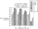
Fig. 5 is a graph illustrating a comparison of blocking probabilities in a heavily loaded system consisting of fourteen UEs.
Fig. 6 is a graph illustrating a comparison of PUCCH utilization for the heavily loaded system shown in fig. 5.
Fig. 7 is a block diagram of a wireless communication network according to one embodiment.
Fig. 8 is a high-level block diagram of a system that may be used as an eNB or UE in accordance with one embodiment.
Figure 9 illustrates EPDCCH-based PUCCH resource allocation in accordance with one embodiment.
FIG. 10 is a graph illustrating reducing ΔAROA block diagram where values are used within one PUCCH resource allocation block.
FIG. 11 is a graph illustrating the use of a large ΔAROA block diagram of values to move from one PUCCH resource allocation block to another block.
Fig. 12 is a block diagram illustrating a modification in which the UE resource allocation moves across neighboring blocks.
Detailed Description
LTE release 11 introduces an Enhanced Physical Downlink Control Channel (EPDCCH). There is a need to determine hybrid automatic repeat request acknowledgement (HARQ-ACK) resources on a Physical Uplink Control Channel (PUCCH) in response to Physical Downlink Shared Channel (PDSCH) transmissions scheduled by the Physical Downlink Control Channel (PDCCH) or EPDCCH.
For PDCCH, the dynamic PUCCH resources are represented by the expression:

Wherein The dynamic PUCCH region is described in terms of a semi-static PUCCH region and is a dynamic PUCCH offset parameter that is either common for the entire cell (cell-specific) or dedicated for a particular UE (UE-specific). Parameter nCCERepresents a first or lowest indexed control channel element of a PDCCH used to schedule corresponding downlink shared channel (DL-SCH) data transmissions on a PDSCH.
For EPDCCH, it has been agreed to configure EPDCCH regions in a UE-specific manner. The UE may be configured with up to two EPDCCH sets to form a UE-specific search space for receiving downlink control information. Each set may contain {2, 4, 8} Physical Resource Block (PRB) pairs and each set consists of a number of Enhanced Control Channel Elements (ECCEs). ECCEs are indexed by EPDCCH set. One or more ECCEs are aggregated for transmission of Downlink Control Information (DCI) messages on the EPDCCH. Based on this EPDCCH definition, the dynamic PUCCH resource allocation is defined in terms of EPDCCH set and modified from equation (1) to

f(neCCE) The term is a function of the lowest index ECCE in the EPDCCH set k used to construct the transmitted EPDCCH. The entry is the semi-statically configured dedicated PUCCH resource start offset for EPDCCH set k. DeltaAROIs a dynamically signaled HARQ-ACK resource indicator offset that may be used to resolve collisions between PUCCH resources from PDCCH and EPDCCH sets. Said ΔAROIt may also be used to resolve conflicts between PUCCH resources associated with the two EPDCCH sets.
PUCCH regions corresponding to PDCCH and EPDCCH DL assignments may be mapped to non-overlapping PUCCH regions. This partitioning avoids possible collisions between PUCCH resources derived from PDCCH and EPDCCH DL assignments. On the other hand, creating non-overlapping regions is not an efficient use of UL freedom, as it limits the uplink frequency resources available for uplink shared channel (UL-SCH) data transmission on the Physical Uplink Shared Channel (PUSCH).
Thus, a degree of overlap between PUCCH regions derived from PDCCH and EPDCCH is allowed and dynamically signaled HARQ-ACK resource indicator offset (Δ @)ARO) It is more efficient to resolve possible PUCCH resource collisions. The 2-bit ARO field is represented by the values [ - δ, 0, δ,2 δ]Where δ is the unit offset value. In one embodiment of the present invention, the ARO described herein is conveyed in a new field in the DCI format scheduling the DL assignment on PDSCH. If the UE receives a value of "0," it indicates that no offset is applied to determine the PUCCH resource of equation (2). Thus, LTE evolved nodeB (enb) has three possible offsets so that it can be used to avoid collision between PUCCH resources when the PUCCH region overlaps between PDCCH and EPDCCH sets. Furthermore, using the unit offset δ of 2 ensures that two consecutive resources can be reserved in the PUCCH transmit diversity case.
To demonstrate the need for ARO, fig. 1 illustrates EPDCCH blocking probabilities considering PUCCH resource blocking between two EPDCCH sets for the case where ARO is not present. The different curves in fig. 1 show different levels of overlap in the PUCCH regions associated with the two EPDCCH sets. Fig. 2 illustrates EPDCCH blocking probability for the case where ARO is present in the case where δ ═ 1. Comparing fig. 1 and fig. 2, it can be seen that for a 10% blocking probability, eight UEs (or rather eight DCI allocations) may be scheduled without an ARO, while at least twelve UEs may be scheduled in the ARO case. This provides a 50% increase in control channel capacity on EPDCCH.
Although ARO reduces the overall blocking probability, ARO also introduces some limitations. For example, if the UE is configured to receive PDSCH on a secondary serving cell (SCell) in carrier aggregation, the UE is also configured to transmit HARQ-ACK feedback using PUCCH format 1b or PUCCH format 3 with channel selection. For any PUCCH format, PUCCH resources corresponding to detected data transmissions on PDSCH on SCell are indicated by HARQ-ACK Resource Indicator (ARI) values conveyed in the Transmit Power Control (TPC) field of DCI scheduling PDSCH. Thus, if EPDCCH schedules PDSCH on SCell, then no separate ARO field in DCI format is needed. Accordingly, embodiments of the present invention include the following options for the ARO field, namely: (1) the ARO field is not configured to be a DCI format, (2) the ARO field is configured to be a DCI format with redundant information, or (3) the ARO field is designated to be reserved when DCI is transmitted on an EPDCCH scheduling a PDSCH on an SCell.
Explicit ARO field for all DC formats
In one embodiment, an explicit ARO field is introduced for all DCI formats transmitted on EPDCCH, except DCI format 4 for scheduling UL MIMO transmissions.
If the UE receives a PDSCH transmission indicated by detecting a DL assignment on the EPDCCH or an EPDCCH indicating a downlink semi-persistent scheduling (SPS) release on the primary cell, the UE decodes the EPDCCH with an explicit 2-bit ARO field in the DCI payload.
The ARO field value indicates a resource offset (Δ) in the range { -2, 0,2, 4}ARO). In other embodiments of the present invention, the range may be { -1, 0, 1, 3} or { -2.-1, 0, 2}, and the main concept taught herein is to define a small offset value to resolve PUCCH resource collisions. Tables 1 and 2 illustrate the alternative Δ of the value in the ARO field in the DCI formatAROAnd (6) mapping.


TABLE 1
| ARO field value | ΔARO |
| 0 | 0 |
| 1 | -1 |
| 2 | -2 |
| 3 | 2 |
TABLE 2
Alternatively, the resource offset range may be configured based on whether the UE is configured for transmit diversity for PUCCH formats 1a/1 b. The ARO field indicates an offset in the range { -2, 0,2, 4} when the UE is configured to transmit PUCCH format 1a/1b on two antenna ports. When the UE is configured to transmit PUCCH format 1a/1b on one antenna port, the ARO field indicates an offset in the range { -1, 0, 1, 2} or in the range {0, 1, 2, 3 }.
The ARO field may be reserved if:
a Time Division Duplex (TDD) UE is configured for PUCCH format 3 and an EPDCCH is detected in a DCI message with a value of a Downlink Assignment Index (DAI) greater than 1; or
In case EPDCCH is detected to schedule PDSCH on configured SCell and UE is configured for PUCCH format 3 or PUCCH format with channel selection 1b, both FDD and TDD carriers are aggregated.
Configuring resources via semi-static state
In another embodiment, an explicit ARO field may be used to indicate a semi-statically configured resource, e.g., one out of a set of four semi-statically configured resources, when the UE is configured for PUCCH format 3 or when the UE is configured for carrier aggregation using PUCCH format 1b with channel selection.
In LTE release 10, the TPC field of the DCI format may be reinterpreted as an ARI value when the UE detects PDSCH on the PDCCH-scheduled SCell. In addition, when a TDD UE configured for single cell operation is configured for PUCCH format 3, the TPC field of the DCI format scheduling the PDSCH may be used to indicate to the ARI whether a Downlink Assignment Index (DAI) value is greater than 1. This embodiment restores the TPC field to its original function of providing TPC commands rather than indicating ARI values.
Thus, when the DAI value is greater than 1 for EPDCCH scheduling PDSCH on the primary cell or EPDCCH indicating SPS release on the primary cell, the TPC field indicates a transmit power control command and the HARQ-ACK Resource Offset (ARO) field indicates one among a set of up to four semi-statically configured PUCCH format 3 resources.
For EPDCCH transmitted on a primary cell and scheduling PDSCH on a secondary cell, a TPC field of the EPDCCH may indicate one among a set of up to four semi-statically configured PUCCH format 3 resources. The ARO field of the EPDCCH may be set to zero or may be reserved (i.e., a value is not defined).
In one alternative, both the TPC field and the ARO field of the EPDCCH may indicate the same PUCCH format 3 among a set of up to four semi-statically configured PUCCH format 3 resources. In another alternative, the TPC field may indicate a TPC command while the ARO field indicates one PUCCH format 3 resource among a set of up to four semi-statically configured PUCCH format 3 resources. The same TPC value is transmitted on both EPDCCHs if the UE detects an EPDCCH on a primary cell scheduling PDSCH on the primary cell and another EPDCCH on a primary cell scheduling PDSCH on the secondary cell in the same subframe.
In yet another alternative, the TPC field and the ARO field may both indicate the same ARI value used to select the PUCCH format 3 resource.
Primary cell only
In yet another embodiment, the explicit ARO field is inserted only in the DCI format carried in the EPDCCH on the primary cell. Assuming the ARO field is present, the UE decodes the EPDCCH on the primary cell. There is no explicit ARO field for EPDCCH on the secondary cell.
PUCCH resource allocation for TDD.
TDD dynamic PUCCH resource allocation corresponding to detected EPDCCH is similar to FDD with one important exception. For TDD, the UE may need to send HARQ-ACK feedback in UL subframes corresponding to PDSCH received in multiple DL subframes. In addition to the semi-static resource offset for EPDCCH set k, PUCCH resources must also be reserved for each DL subframe of the HARQ-ACK bundling window of length M. The HARQ-ACK bundling window is also referred to as DL association set. The length M of the DL association set depends on the tdd UL/DL configuration and the UL subframe.
The PUCCH resource region for EPDCCH scheduling is allocated in sequence for each subframe of the HARQ-ACK DL association set of length M. In particular, for the ith DL subframe, the PUCCH region is offset by the total number of ECCEs in all preceding subframes 0, …, i-1. Fruit needleFor sub-frame n-kmThere is N in EPDCCH set qeCCE,q,mOne ECCE, then for sub-frame n-kmThe transmitted PDSCH will be NeCCE,q,mThe same number of PUCCH resources remain in UL subframe n.
For antenna port p0 corresponding to sub-frame n-kmThe dynamic PUCCH resource allocation of (a) is represented by the following formula:

Wherein the content of the first and second substances,

and isIs the number of ECCEs in the resource block used for EPDCCH set q.
According to equation (3), it can be observed that PUCCH overhead for EPDCCH-based dynamic PUCCH resource allocation can be substantial. As such, it is desirable to design methods to compress PUCCH resource allocation to improve PUSCH transmission capacity. The HARQ-ACK resource offset indicator in this case can thus be used for two purposes:
(1) for avoiding PUCCH resource collision between EPDCCH sets and/or between EPDCCH and PDCCH (similar to FDD); and
(2) for reserving PUCCH resource compression between PUCCH regions for each DL subframe in the HARQ-ACK bundling window.
Incorporating some resource compression reduces the degrees of freedom available for resource collisions compared to FDD. For a full-load system where a large number of UEs are scheduled in each subframe, resource compression may not be necessary, as PUCCH transmission requires one PUCCH region per DL subframe. For this scenario, it is desirable to specify the same collision avoidance capability for TDD and FDD.
PUCCH resource compression and collision avoidance method
A 3-bit ARO field.
In one embodiment, the ARO field size may be set to 3 bits in order to support both collision avoidance and PUCCH resource compression. Table 3 illustrates an exemplary mapping of ARO field values in a DCI format to PUCCH resources in equation 3 above.
TABLE 3
For option 1 in table 3, the last four inputs offset the PUCCH resource for the ith DL subframe by the number of ECCEs in subframe i-1 of EPDCCH set q. These inputs maintain the resource collision avoidance capability as in FDD by further offsetting by the value { -2, 0, 1, 2 }. This approach allows resource compression of approximately one DL subframe. For example, for TDD UL/DL configuration 2 where the length M of the DL association set is 4 in both UL subframe n-2 and n-7, implicit resource allocation may be saved for the fourth DL subframe of the DL association set. Different mappings of ARO values consisting of a mixture of resource compression and collision avoidance may also be used in other embodiments.
For option 2 of table 3, the last four inputs offset the resource allocation in one or more previous DL subframes by the number of ECCEs allocated to set q.
Tradeoff PUCCH resource collision avoidance and resource compression.
TDD PUCCH resource compression reduces resource collision avoidance capability if the ARO field size is unchanged relative to FDD. If this is deemed acceptable in order to keep the same ARO field size in the DCI format for both duplex modes, the following set of values may be used at various options.
For the ith subframe of the DL association set, the ARO value set is expressed as
ΔARO∈{0,2,-NECCE,q,i-1-1,-NECCE,q,i-1-2} i>0。
For subframe i ═ 0, this set reverts back to the same set for FDD, i.e., {0,2, -1, -2}, whereas for i > 1, resource compression of one DL subframe is possible.
For the ith subframe of the HARQ-ACK bundling window, the ARO value set is expressed as
ΔARO∈{0,2,-NECCE,i-1,j+1,-NECCE,i-1,j+2} i>0。
For subframe i ═ 0, this set reverts back to the same set for FDD, i.e., {0,2, -1, -2}, whereas for i > 1, resource compression of one DL subframe is possible.
Alternatively, an ARO set may be defined as
ΔARO∈{0,2,-1,-NECCE,q,0} i=1
ΔARO∈{0,2,-NECCE,q,0,-(NECC,q,0+NECCE,q,1)} i=2
ΔARO∈{0,-NECC,q,0,-(NECC,q,0+NECCE,q,1),-(NECC,q,0+NECCE,q,1+NECCE,q,2)} i>2
Other alternative options are not excluded as the main concept of the present teachings is that both small and large offsets can be designed for the ARO field. The small offset is used to resolve PUCCH resource conflicts between assignments in the two EPDCCH sets or between an EPDCCH set and a PDCCH-based resource allocation. On the other hand, large offsets are used to compress PUCCH resources by moving from one reserved block to another.
Fig. 3 is a graph illustrating a comparison of blocking probabilities under the condition of two EPDCCH sets, TDD UL/DL configuration # 2, and a lightly loaded system consisting of four UEs.
Fig. 4 is a graph illustrating a comparison of PUCCH utilization for the lightly loaded system shown in fig. 3.
Fig. 5 is a graph illustrating a comparison of blocking probabilities under conditions of two EPDCCH sets, TDD UL/DL configuration # 2, and a heavily loaded system consisting of fourteen UEs.
Fig. 6 is a graph illustrating a comparison of PUCCH utilization for the heavily loaded system shown in fig. 5.
Fig. 3-6 compare options 1, 2, and 3 as described above. As a reference, the results in the case of no ARO and the results using the FDD ARO set {0,2, -1, -2} are included in the comparison.
Fig. 3 and 5 show the blocking probability for each scheduled DL subframe (assuming all UEs are scheduled in each subframe of the bundling window). Fig. 4 and 6 show PUCCH utilization for each PUCCH sub-region corresponding to each of the scheduled DL subframes. The comparison results illustrated in fig. 3-6 may be summarized as follows.
For lightly loaded systems, all ARO options (including FDD ARO set) achieve the intended goal of reducing the blocking probability relative to no ARO indication. Thus, one PUCCH sub-region may be saved for all three options for combining resource compression with collision avoidance. In one embodiment, options 1 and 2 achieve the best PUCCH utilization. For sixteen ECCEs in the EPDCCH set, this translates to approximately one PRB (assuming the eNB allocates eighteen format 1a/1b resources in one PRB).
For heavily loaded systems, although PUCCH utilization is close to 100% in the first sub-region, there is still considerable PUCCH utilization in the last sub-region (i.e., no PUCCH savings compared to using FDD ARO set). Furthermore, from a system perspective, there may be no significant gain to minimize PUCCH overhead for a fully loaded system. While it may be considered that the PUCCH resource utilization for FDD is lower where higher aggregation levels are more likely to be transmitted, it is not necessarily desirable to increase the packing efficiency per PUCCH PRB due to the resulting higher intra-cell interference (this also applies to PDCCH-based PUCCH resource allocation).
Fig. 5 also indicates that the blocking probability is low for option 3, since for each DL subframe more freedom is used for resource compression to the detriment of collision avoidance. In contrast, options 1 and 2 appear to efficiently utilize the degrees of freedom to provide both resource compression and collision avoidance capabilities.
Monitoring settings for FPDCCH for PUCCH resource allocation
LTE release 11 UEs may be configured to monitor EPDCCH on a subset of all possible DL and special subframes. When a UE is not configured to monitor EPDCCH in a subframe, the UE monitors legacy PDCCH for DL assignments, including PDCCH indicating SPS release and UL grants. It may happen that in the same DL association set of length M > 1, the UE may be configured to monitor EPDCCH in some subframes and PDCCH in other subframes. For such scenarios, PUCCH resource allocation needs to be specified.
For detecting corresponding EPDCCH or indicating subframe n-kmPDSCH transmission indicated by EPDCCH of downlink SPS release in, PUCCH resource for antenna port p0 is
Wherein S(m)DL association set (n-k) configured to monitor EPDCCH for its UEs0,n-k1,…,n-km-1DL subframe subset in (1).
This TDD resource allocation means that if the UE is configured to monitor EPDCCH in all M DL subframes of the DL association set, then
PUCCH resources should be reserved for set q. The worst case occurs for TDD UL-DL configuration 5 with nine DL subframes and one UL subframe.
Fig. 7 is a block diagram of a wireless communication network 700, which may be an LTE network utilizing Orthogonal Frequency Division Multiple Access (OFDMA) on the downlink and single carrier frequency division multiple access (SC-FDMA) on the uplink. LTE partitions system bandwidth into multiple orthogonal subcarriers, which may be referred to as tones or bins. Each subcarrier may be modulated with a data, control, or reference signal. The wireless network 700 includes a number of evolved node bs (enbs) 701 and other network entities. The eNB701 communicates with user equipment devices (UEs) 702, 705. Each eNB701 provides communication services for a particular geographic area or "cell" 703. For example, eNB701 may be a macro base station, a micro base station, a pico base station, or a femto base station. A network controller 704 may be coupled to a set of enbs 701 and provide coordination and control for these enbs 701.
The UEs 702, 705 may be stationary or mobile and may be located throughout the wireless network 700. The UEs 702, 705 may be referred to as terminals, mobile stations, subscriber units, stations, such as mobile phones, Personal Digital Assistants (PDAs), wireless modems, laptop or notebook computers, tablets, and the like. The UE 702 communicates with an eNB701 serving a cell 703 in which the UE 702 is located.
A UE 702 may communicate with more than one eNB701 if the cells 703 of the enbs 701 overlap. One eNB701 will be the primary cell (PCell) and the other enbs 701 will be secondary serving cells (scells).
Fig. 8 is a high-level block diagram of a system 800 that may be used as an eNB or UE (which may be, for example, eNB701 or UE 702 in fig. 7). The system 800 receives data to be transmitted from the interface 801 at a transmit processor 802. For example, the data may include audio or video information or other data file information to be transmitted on the PUSCH. The transmit processor 802 may also receive control or HARQ-ACK information to be transmitted on PUCCH, PUSCH, or SRS from the controller 803. A transmit processor 802 processes (e.g., encodes and symbol maps) the data and control information to obtain data symbols, control symbols, and reference symbols. Transmit processor 802 can also perform spatial processing or precoding for the data symbols and/or control symbols and the reference symbols. The output of the transmit processor 802 is provided to a modem 804. The modem 804 processes the output symbol stream from the transmit processor 802 to obtain an output sample stream, which is further processed by conversion to analog, amplification, and frequency up conversion before being transmitted via the antenna 805. In other embodiments, multiple modems 804 may be used to support multiple-input multiple-output (MIMO) transmission on multiple antennas 805.
Signals from other devices are also received at system 800 over antenna 805. The received signal is provided to modem 804 for demodulation. The modem 804 processes the signal, e.g., by screening, amplifying, down converting, and/or digitizing, to obtain input samples. Modem 804 or receive processor 806 may further process the input samples to obtain received symbols. A receive processor 806 then processes the symbols by, for example, demodulation, deinterleaving, and/or decoding. The receive processor 805 then provides the decoded data to the interface 801 for use by the eNB or UE. The receive processor further provides the decoded control information to a controller 803.
The controller 803 may direct the operation of the system 800 in an eNB or UE, e.g., by adjusting time and power levels. A memory 807 may store data and program codes for the controller 803, the transmit processor 802, and/or the receive processor 806. Additional components, such as scheduler 808, can schedule downlink and/or uplink data transmissions on one or more component carriers by system 800 (e.g., in an eNB).
Figure 9 illustrates EPDCCH-based PUCCH resource allocation in accordance with one embodiment. The eNodeB901 transmits on a downlink channel to the UE 902. For example, eNodeB901 will have M EPDCCHs and PDSCHs in M downlink subframes 903-1 to 903-M (in subframe n-k)0From start to subframe n-kM-1) Up to the UE 902. In the subsequent uplink subframe n, the UE 902 must feed back HARQ-ACKs 904 for the M downlink subframes 903 to the eNodeB 901. eNodeB901 reserves PUCCH resources 905 for M subframes. For FDD, M ═ 1 and k 04. For TDD, M > 1 and km≧ 4 and the value is dependent on the UL subframe and TDD UL/DL configuration, as shown in Table 4. Embodiments of the invention disclosed herein provide systems and methods for PUCCH resource compression that conserve PUCCH resources when PDSCH is scheduled by EPDCCH. In addition, embodiments avoid PUCCH resource collisions between multiple UEs and/or between multiple EPDCCH sets.
Dynamic HARQ-ACK resource offset (Delta)ARO) For compressing PUCCH resources in UL subframe 904, as shown in equation 3 above.
FIG. 10 is a graph illustrating reducing ΔAROA block diagram where values are used within one PUCCH resource allocation block. Using a relatively small Δ for FDD and TDDAROValue 1001, UE moves from resource 1002 to resource 1003 within PUCCH resource allocation block 1004. This movement within a single PUCCH resource allocation block is used to avoid collisions between different UEs.

TABLE 4
FIG. 11 is a graph illustrating the use of a large ΔAROA block diagram of values to move from one PUCCH resource allocation block to another block. For TDD with M-4 downlink subframes, a relatively large Δ is usedAROValue 1101, UE moves from 1102 in PUCCH resource allocation block 1103 to 1104 within PUCCH resource allocation block 1105. This mobile saves the PUCCH resource allocation block 1103.
Fig. 12 is a modification illustrating the embodiment shown in fig. 11, in which the UE resource allocation moves across neighboring blocks. In FIG. 12, ΔARO1201 moves the UE resource allocation from 1202 in block 1203 to 1204 in block 1205.
FDD HARQ-ACK procedure for one configured serving cell
For PDSCH transmissions indicated by detection of the corresponding EPDCCH in subframe n-4, or for EPDCCH indicating downlink SPS release in subframe n-4, the UE should use:

in case the EPDCCH-PRB set is configured for distributed transmission; or

In case the EPDCCH-PRB set is configured for localized transmission.
These values are for the antenna port p0. Wherein n isECCE,qThe number of first ECCEs (i.e. the lowest ECCE index used to construct the EPDCCH) assigned for transmitting the corresponding DCI in the EPDCCH-PRB set q. DeltaAROThe value is based on determining the HARQ-ACK resource offset word in the DCI format corresponding to the EPDCCHSegment determination, as given in Table 5 below, Table 5 refers to the ACK/NACK resource offset field to Δ in DCI Format 1A/1B/1D/1/2A/2/2B/2C/2DAROAnd (4) mapping of values. Of EPDCCH-PRB set q Is configured by higher layer parameters designated pucch-ResourceStartOffset-r 11. Of EPDCCH-PRB set q
 In 3gpp ts 36.211: "evolved universal terrestrial radio access (E-UTRA); physical channel and modulation "is given in section 6.8 a.1. n' is determined in terms of the antenna port used for localized EPDCCH transmission (which is described in section 6.8a.5 in 3GPP TS 36.211).
For two antenna port transmission, for antenna port p1Is represented by the following formula

In case the EPDCCH-PRB set is configured for distributed transmission; or

In case the EPDCCH-PRB set is configured for localized transmission.

TABLE 5
Those skilled in the art will appreciate that modifications may be made to the described embodiments and that many other embodiments are possible within the scope of the claimed invention.
Claims (18)
1. A method for selecting physical uplink control channel, PUCCH, resources, comprising:
detecting an enhanced physical downlink control channel, EPDCCH, in a signal received from a base station in a first subframe;
detecting a resource offset field value in a Downlink control information, DCI, format of the EPDCCH, the resource offset field value indicating in a range {0,2, -NECCE,q,i-1–1,-NECCE,q,i-1Resource offset Δ in-2 }AROValue of wherein NECCE,q,i-1The number of enhanced control channel elements ECCEs in subframe i-1 of EPDCCH set q;
determining the resource offset Δ for the EPDCCH based on a detected resource offset field value in the DCI formatAROA value; and
selecting a PUCCH resource for transmitting hybrid automatic repeat request acknowledgement (HARQ-ACK) corresponding to the EPDCCH, wherein the PUCCH resource is based on the deltaAROThe value is selected.
2. The method of claim 1, further comprising selecting a second PUCCH resource for transmitting HARQ-ACKs on a second antenna port.
3. The method of claim 1, wherein the resource offset field is a detect HARQ-ACK resource offset field value in a downlink control information, DCI, format of the EPDCCH.
4. The method of claim 3, wherein a table maps the HARQ-ACK resource offset field values for certain DCI formats to ΔAROThe value is obtained.
5. The method of claim 3, wherein the HARQ-ACK resource offset field value is a two-bit field in a DCI payload.
6. The method of claim 5, wherein the two-bit field corresponds to Δ in the range {0, -1, -2,2}AROThe value is obtained.
7. The method of claim 1, wherein the ΔAROThe value indicates one among a set of semi-statically configured PUCCH resources.
8. The method of claim 3, wherein a HARQ-ACK resource offset field in the DCI format of the EPDCCH is used to indicate a small offset or a large offset.
9. The method of claim 8, further comprising offsetting a two-bit offset field ΔAROInserted in an EPDCCH set of downlink assignments on a scheduling physical downlink shared channel, PDSCH; and for sub-frame n-kmThe value of the offset field of the PUCCH resource allocation of (a) indicates a range {0, -1, -NECCE,q,m-1–1,NECCE,q,m-1-2 }.
10. A user equipment device, comprising:
a receiver processor circuit configured to:
detecting an enhanced physical downlink control channel, EPDCCH, in a signal received from a base station in subframe n;
detecting a resource offset field value in a Downlink control information, DCI, format of the EPDCCH, the resource offset field value indicating in a range {0,2, -NECCE,q,i-1–1,-NECCE,q,i-1Resource offset value in-2, where NECCE,q,i-1The number of enhanced control channel elements ECCEs in subframe i-1 of EPDCCH set q; a transmit processor circuit configured to:
selecting a physical uplink control channel, PUCCH, resource for the base station to transmit a hybrid automatic repeat request acknowledgement, HARQ-ACK, in subframe n +4, the PUCCH resource selected based on the resource offset field value; and
a modem configured to transmit the PUCCH resources to the base station.
11. The user equipment device of claim 10, wherein the transmit processor circuit is further configured to select a second PUCCH resource for transmission of HARQ-ACK on a second antenna port.
12. The user equipment device of claim 10, wherein the transmit processor circuit is further configured to look up a delta in a table based on the resource offset field valueAROOffset to identify the delta of the EPDCCHAROAnd (4) offsetting.
13. The user equipment device of claim 12, wherein the table maps the resource offset field values of certain DCI formats to ΔAROAn offset value.
14. The user equipment device of claim 12, wherein the resource offset field value is a two-bit field in a DCI payload.
15. The user equipment device of claim 14, wherein the two-bit field corresponds to a resource offset value in the range {0, -1, -2,2 }.
16. The user equipment device of claim 14, wherein the two-bit field corresponds to a range {0, -1, -NECCE,q,m-1–1,NECCE,q,m-1-2} resource offset value.
17. The user equipment device of claim 10, wherein the resource offset value indicates one among a set of semi-statically configured PUCCH resources.
18. The user equipment device of claim 14, wherein HARQ-ACK feedback information is transmitted on the indicated PUCCH resources.
Priority Applications (2)
| Application Number | Priority Date | Filing Date | Title |
|---|---|---|---|
| CN202010071852.5A CN111277398B (en) | 2012-11-02 | 2013-11-04 | Efficient allocation of uplink HARQ-ACK resources |
| CN202210998629.4A CN115208547A (en) | 2012-11-02 | 2013-11-04 | Efficient allocation of uplink HARQ-ACK resources |
Applications Claiming Priority (11)
| Application Number | Priority Date | Filing Date | Title |
|---|---|---|---|
| US201261721880P | 2012-11-02 | 2012-11-02 | |
| US61/721,880 | 2012-11-02 | ||
| US201361750157P | 2013-01-08 | 2013-01-08 | |
| US61/750,157 | 2013-01-08 | ||
| US201361755675P | 2013-01-23 | 2013-01-23 | |
| US61/755,675 | 2013-01-23 | ||
| US201361767012P | 2013-02-20 | 2013-02-20 | |
| US61/767,012 | 2013-02-20 | ||
| US14/026,878 US11245507B2 (en) | 2012-11-02 | 2013-09-13 | Efficient allocation of uplink HARQ-ACK resources for LTE enhanced control channel |
| US14/026,878 | 2013-09-13 | ||
| PCT/US2013/068315 WO2014071304A1 (en) | 2012-11-02 | 2013-11-04 | Efficient allocation of uplink harq-ack resources |
Related Child Applications (2)
| Application Number | Title | Priority Date | Filing Date |
|---|---|---|---|
| CN202010071852.5A Division CN111277398B (en) | 2012-11-02 | 2013-11-04 | Efficient allocation of uplink HARQ-ACK resources |
| CN202210998629.4A Division CN115208547A (en) | 2012-11-02 | 2013-11-04 | Efficient allocation of uplink HARQ-ACK resources |
Publications (2)
| Publication Number | Publication Date |
|---|---|
| CN104782204A CN104782204A (en) | 2015-07-15 |
| CN104782204B true CN104782204B (en) | 2020-02-21 |
Family
ID=50622323
Family Applications (3)
| Application Number | Title | Priority Date | Filing Date |
|---|---|---|---|
| CN201380055693.8A Active CN104782204B (en) | 2012-11-02 | 2013-11-04 | Efficient allocation of uplink HARQ-ACK resources |
| CN202210998629.4A Pending CN115208547A (en) | 2012-11-02 | 2013-11-04 | Efficient allocation of uplink HARQ-ACK resources |
| CN202010071852.5A Active CN111277398B (en) | 2012-11-02 | 2013-11-04 | Efficient allocation of uplink HARQ-ACK resources |
Family Applications After (2)
| Application Number | Title | Priority Date | Filing Date |
|---|---|---|---|
| CN202210998629.4A Pending CN115208547A (en) | 2012-11-02 | 2013-11-04 | Efficient allocation of uplink HARQ-ACK resources |
| CN202010071852.5A Active CN111277398B (en) | 2012-11-02 | 2013-11-04 | Efficient allocation of uplink HARQ-ACK resources |
Country Status (4)
| Country | Link |
|---|---|
| US (2) | US11245507B2 (en) |
| JP (3) | JP6497706B2 (en) |
| CN (3) | CN104782204B (en) |
| WO (1) | WO2014071304A1 (en) |
Families Citing this family (46)
| Publication number | Priority date | Publication date | Assignee | Title |
|---|---|---|---|---|
| KR101600655B1 (en) | 2009-06-16 | 2016-03-07 | 샤프 가부시키가이샤 | Mobile station apparatus, base station apparatus, radio communication method and integrated circuit |
| US9246656B2 (en) | 2011-06-24 | 2016-01-26 | Lg Electronics Inc. | Method for transmitting uplink control information, user equipment, method for receiving uplink control information, and base station |
| EP3136806B8 (en) * | 2012-09-27 | 2022-08-31 | Sun Patent Trust | Wireless communication terminal, base station device, and resource allocation method |
| US11245507B2 (en) * | 2012-11-02 | 2022-02-08 | Texas Instruments Incorporated | Efficient allocation of uplink HARQ-ACK resources for LTE enhanced control channel |
| US9717089B2 (en) * | 2012-11-29 | 2017-07-25 | Lg Electronics Inc. | Method and apparatus for transmitting acknowledgement of reception in wireless communication system |
| CN104854773B (en) | 2013-01-14 | 2018-05-11 | 英特尔Ip公司 | Energy acquisition equipment in wireless network |
| US9112662B2 (en) * | 2013-01-17 | 2015-08-18 | Samsung Electronics Co., Ltd. | Overhead reduction for transmission of acknowledgment signals |
| TWI615050B (en) * | 2013-01-18 | 2018-02-11 | 諾基亞對策與網路公司 | Aro values in pucch resource allocation for epdcch in tdd |
| JP6006881B2 (en) * | 2013-01-31 | 2016-10-12 | エルジー エレクトロニクス インコーポレイティド | Reception confirmation response transmission method and apparatus in wireless communication system |
| US9397796B2 (en) * | 2013-03-13 | 2016-07-19 | Samsung Electronics Co., Ltd. | Computing and transmitting channel state information in adaptively configured TDD communication systems |
| WO2014189304A1 (en) * | 2013-05-22 | 2014-11-27 | 엘지전자 주식회사 | Communication method for terminal in wireless communication system and terminal using same |
| US9749996B2 (en) * | 2013-07-29 | 2017-08-29 | Lg Electronics Inc. | Method and device for performing coordinated multi-point transmission based on selection of transmission point |
| JP6424393B2 (en) * | 2013-09-26 | 2018-11-21 | シャープ株式会社 | Terminal device, base station device, and communication method |
| WO2015122734A1 (en) * | 2014-02-14 | 2015-08-20 | 엘지전자 주식회사 | Method and apparatus for transmitting harq-ack in wireless communication system |
| US10492216B2 (en) * | 2014-09-24 | 2019-11-26 | Telefonaktiebolaget Lm Ericsson (Publ) | Method and BS for scheduling UE, and method and UE for transmitting HARQ |
| US9800387B2 (en) * | 2014-11-06 | 2017-10-24 | Intel IP Corporation | Computing apparatus with cross-subframe scheduling |
| US10568072B2 (en) | 2014-12-31 | 2020-02-18 | Lg Electronics Inc. | Method for allocating resource in wireless communication system and apparatus therefor |
| EP3242433B1 (en) | 2014-12-31 | 2020-03-11 | LG Electronics Inc. | Method for transmitting ack/nack in wireless communication system and device using same |
| US9985742B2 (en) * | 2015-04-06 | 2018-05-29 | Samsung Electronics Co., Ltd. | Transmission power control for an uplink control channel |
| US11362759B2 (en) | 2015-04-06 | 2022-06-14 | Samsung Electronics Co., Ltd. | Transmission power control for an uplink control channel |
| JP6833166B2 (en) * | 2015-04-10 | 2021-02-24 | テレフオンアクチーボラゲット エルエム エリクソン(パブル) | Implementation of HARQ on PUSCH for multiple carriers |
| WO2016206083A1 (en) * | 2015-06-26 | 2016-12-29 | 华为技术有限公司 | Method and apparatus for uplink data transmission |
| EP3340673A4 (en) * | 2015-08-21 | 2019-04-17 | Ntt Docomo, Inc. | User terminal, wireless base station, and wireless communication method |
| WO2017078128A1 (en) * | 2015-11-05 | 2017-05-11 | 株式会社Nttドコモ | User terminal, radio base station and radio communication method |
| CN106686741B (en) * | 2015-11-11 | 2020-04-14 | 华为技术有限公司 | Method, device, storage medium and communication system for transmitting scheduling information |
| WO2017149194A1 (en) * | 2016-03-01 | 2017-09-08 | Nokia Technologies Oy | Pucch resource allocation |
| CN108886754B (en) * | 2016-04-07 | 2021-07-23 | 瑞典爱立信有限公司 | Method for indicating transmission time offset of feedback message |
| US10440706B2 (en) * | 2016-08-08 | 2019-10-08 | Sharp Kabushiki Kaisha | Systems and methods for PUCCH resource allocation and HARQ-ACK reporting with processing time reduction |
| TWI624168B (en) * | 2016-10-21 | 2018-05-11 | 元智大學 | An intelligent deployment cascade control device based on an fdd-ofdma indoor small cell in multi-user and interference environments |
| CN108024345B (en) * | 2016-11-04 | 2023-04-28 | 中兴通讯股份有限公司 | Method and device for determining transmission resources of uplink control information |
| EP3531599A4 (en) * | 2016-11-04 | 2019-11-06 | Huawei Technologies Co., Ltd. | Harq-ack feedback information transmission method and related apparatus |
| CN108306720B (en) * | 2017-01-13 | 2022-06-21 | 北京三星通信技术研究有限公司 | Method and equipment for transmitting UCI information |
| WO2019028735A1 (en) * | 2017-08-10 | 2019-02-14 | Lenovo (Beijing) Limited | Uplink control channel resource determination |
| US10715283B2 (en) * | 2017-10-02 | 2020-07-14 | Kt Corporation | Apparatus and method of transmitting and receiving HARQ ACK/NACK information for new radio |
| US10306669B2 (en) | 2017-10-26 | 2019-05-28 | Telefonaktiebolaget Lm Ericsson (Publ) | Physical uplink control channel (PUCCH) resource allocation |
| CN114245461A (en) * | 2017-10-26 | 2022-03-25 | 瑞典爱立信有限公司 | Physical Uplink Control Channel (PUCCH) resource allocation |
| CN110351019B (en) * | 2018-04-04 | 2020-12-15 | 华为技术有限公司 | Communication method and device |
| FI3607686T3 (en) * | 2018-04-06 | 2023-07-18 | Ericsson Telefon Ab L M | Power control for feedback signaling |
| US11368260B2 (en) * | 2018-05-03 | 2022-06-21 | Mediatek Singapore Pte. Ltd. | Method and apparatus for reporting hybrid automatic repeat request-acknowledge information in mobile communications |
| CN112385283A (en) * | 2018-05-07 | 2021-02-19 | 株式会社Ntt都科摩 | User terminal and wireless communication method |
| CN117318893A (en) * | 2018-08-09 | 2023-12-29 | 北京三星通信技术研究有限公司 | Uplink transmission method, user equipment, base station and computer readable medium |
| JP6934965B2 (en) | 2019-02-20 | 2021-09-15 | 華碩電腦股▲ふん▼有限公司 | Methods and devices for processing side-link and uplink HARQ-ACK feedback in wireless communication systems |
| CN112583543B (en) * | 2019-09-27 | 2022-08-02 | 维沃移动通信有限公司 | Resource determination method and communication equipment |
| CA3195885A1 (en) | 2020-10-19 | 2022-04-28 | XCOM Labs, Inc. | Reference signal for wireless communication systems |
| WO2022093988A1 (en) | 2020-10-30 | 2022-05-05 | XCOM Labs, Inc. | Clustering and/or rate selection in multiple-input multiple-output communication systems |
| US11778607B2 (en) | 2021-04-01 | 2023-10-03 | Nokia Technologies Oy | Using relative transmission occasion delay indexing |
Citations (2)
| Publication number | Priority date | Publication date | Assignee | Title |
|---|---|---|---|---|
| CN102316595A (en) * | 2011-09-30 | 2012-01-11 | 中兴通讯股份有限公司 | Resource determination method and device for physical uplink control channel (PUCCH) of large-band-width system |
| CN102573094A (en) * | 2012-01-17 | 2012-07-11 | 电信科学技术研究院 | Method and device for transmitting DCI (downlink control information) |
Family Cites Families (23)
| Publication number | Priority date | Publication date | Assignee | Title |
|---|---|---|---|---|
| KR100703287B1 (en) * | 2005-07-20 | 2007-04-03 | 삼성전자주식회사 | System and method for transmitting/receiving resource allocation information in a communication system |
| KR101410120B1 (en) | 2007-08-21 | 2014-06-25 | 삼성전자주식회사 | Apparatus and method for transmitting/receiving the hybrid- arq ack/nack signal in mobile communication system |
| KR20100011879A (en) * | 2008-07-25 | 2010-02-03 | 엘지전자 주식회사 | Method of receiving data in wireless communication system |
| KR101573072B1 (en) * | 2008-08-27 | 2015-12-01 | 엘지전자 주식회사 | Method of transmitting control information in wireless communication system |
| KR101629298B1 (en) | 2008-10-30 | 2016-06-10 | 엘지전자 주식회사 | Method of transmitting control signal in wireless communication system and appratus therefore |
| KR101715938B1 (en) | 2009-03-03 | 2017-03-14 | 엘지전자 주식회사 | Method and apparatus for transmitting harq ack/nack signal in multiple antenna system |
| CN101841892B (en) * | 2009-03-18 | 2012-10-03 | 中国移动通信集团公司 | Method, equipment and system for indicating and detecting PDCCH in a carrier aggregation system |
| SG182371A1 (en) | 2010-01-08 | 2012-08-30 | Interdigital Patent Holdings | Method and apparatus for channel resource mapping in carrier aggregation |
| MX2013001971A (en) * | 2010-08-20 | 2013-05-09 | Ericsson Telefon Ab L M | Arrangement and method for identifying pucch format 3 resources |
| KR101771550B1 (en) * | 2010-10-15 | 2017-08-29 | 주식회사 골드피크이노베이션즈 | Method of Transmitting and Receiving Ack/Nack Signal and Apparatus Thereof |
| CN102098151B (en) * | 2010-12-28 | 2015-08-12 | 中兴通讯股份有限公司 | A kind of sending method of correct/error response message and user terminal |
| CN102638879A (en) * | 2011-02-12 | 2012-08-15 | 北京三星通信技术研究有限公司 | Method for allocating acknowledgement (ACK)/negative acknowledgement (NACK) channel resource |
| KR101919780B1 (en) * | 2011-03-03 | 2018-11-19 | 엘지전자 주식회사 | Method and apparatus for transmitting acknowledgment information in a wireless communication system |
| CN102215094B (en) * | 2011-06-01 | 2013-11-20 | 电信科学技术研究院 | Method, system and equipment for sending and receiving uplink feedback information |
| JP5895388B2 (en) * | 2011-07-22 | 2016-03-30 | シャープ株式会社 | Terminal device, base station device, integrated circuit, and communication method |
| EP4007196B1 (en) * | 2012-03-05 | 2023-09-20 | Samsung Electronics Co., Ltd. | Harq-ack signal transmission in response to detection of control channel type in case of multiple control channel types |
| US8743820B2 (en) * | 2012-05-30 | 2014-06-03 | Intel Corporation | PUCCH resource allocation with enhanced PDCCH |
| US9338775B2 (en) * | 2012-05-31 | 2016-05-10 | Lg Electronics Inc. | Method for transceiving control signals and apparatus therefor |
| WO2014020822A1 (en) * | 2012-08-02 | 2014-02-06 | パナソニック株式会社 | Base station device, terminal device, resource allocation method and response signal transmission method |
| US8923880B2 (en) * | 2012-09-28 | 2014-12-30 | Intel Corporation | Selective joinder of user equipment with wireless cell |
| WO2014054887A1 (en) * | 2012-10-02 | 2014-04-10 | 한양대학교 산학협력단 | Method for transmitting and receiving downlink signal and channel, terminal therefor, and base station therefor |
| US11245507B2 (en) * | 2012-11-02 | 2022-02-08 | Texas Instruments Incorporated | Efficient allocation of uplink HARQ-ACK resources for LTE enhanced control channel |
| WO2014077607A1 (en) * | 2012-11-14 | 2014-05-22 | 엘지전자 주식회사 | Method for operating terminal in carrier aggregation system, and apparatus using said method |
-
2013
- 2013-09-13 US US14/026,878 patent/US11245507B2/en active Active
- 2013-11-04 CN CN201380055693.8A patent/CN104782204B/en active Active
- 2013-11-04 JP JP2015541834A patent/JP6497706B2/en active Active
- 2013-11-04 CN CN202210998629.4A patent/CN115208547A/en active Pending
- 2013-11-04 CN CN202010071852.5A patent/CN111277398B/en active Active
- 2013-11-04 WO PCT/US2013/068315 patent/WO2014071304A1/en active Application Filing
-
2018
- 2018-12-21 JP JP2018240280A patent/JP7148768B2/en active Active
-
2021
- 2021-10-15 JP JP2021169512A patent/JP7344264B2/en active Active
-
2022
- 2022-02-07 US US17/666,120 patent/US20220158802A1/en active Pending
Patent Citations (2)
| Publication number | Priority date | Publication date | Assignee | Title |
|---|---|---|---|---|
| CN102316595A (en) * | 2011-09-30 | 2012-01-11 | 中兴通讯股份有限公司 | Resource determination method and device for physical uplink control channel (PUCCH) of large-band-width system |
| CN102573094A (en) * | 2012-01-17 | 2012-07-11 | 电信科学技术研究院 | Method and device for transmitting DCI (downlink control information) |
Non-Patent Citations (1)
| Title |
|---|
| Remaining aspects of PUCCH resource for EPDCCH;Sharp;《3GPP TSG RAN WG1 Meeting #70bis》;20120929;第1节、第3节、第5节、第6.1节 * |
Also Published As
| Publication number | Publication date |
|---|---|
| WO2014071304A1 (en) | 2014-05-08 |
| JP2019092161A (en) | 2019-06-13 |
| CN111277398B (en) | 2023-04-04 |
| CN111277398A (en) | 2020-06-12 |
| US20140126491A1 (en) | 2014-05-08 |
| CN104782204A (en) | 2015-07-15 |
| JP7148768B2 (en) | 2022-10-06 |
| US11245507B2 (en) | 2022-02-08 |
| JP7344264B2 (en) | 2023-09-13 |
| CN115208547A (en) | 2022-10-18 |
| US20220158802A1 (en) | 2022-05-19 |
| JP2016504803A (en) | 2016-02-12 |
| JP2022009178A (en) | 2022-01-14 |
| JP6497706B2 (en) | 2019-04-10 |
Similar Documents
| Publication | Publication Date | Title |
|---|---|---|
| JP7344264B2 (en) | Efficient allocation of uplink HARQ-ACK resources | |
| US11064471B2 (en) | Method and apparatus for transmitting uplink control information in carrier aggregation system | |
| US10869330B2 (en) | Communication method and device in mobile communication system | |
| US10084590B2 (en) | Data transmission in carrier aggregation with different carrier configurations | |
| US10135581B2 (en) | Method, UE and basestation for reporting/receiving HARQ ACK/NACK for PDSCH in dynamic TDD configurations | |
| KR102278389B1 (en) | Method and apparatus for transmission and reception with reduced transmission time interval in wirelss cellular communication system | |
| KR102616557B1 (en) | A method and apparatus for transmission and reception of data and control information in wireless communication system | |
| EP2899907B1 (en) | Method and device for receiving or transmitting downlink control signal in wireless communication system | |
| US11705993B2 (en) | Semi-static HARQ-ACK codebook enhancements for NR-U | |
| EP3145104B1 (en) | Methods and systems for tdd pucch harq resource allocation for enhanced physical downlink control channel (epdcch) | |
| EP3582427B1 (en) | Node and method for uplink scheduling and hybrid automatic repeat request timing | |
| US20130051356A1 (en) | Device and method for transmitting downlink control information in a wireless communication system | |
| US10057038B2 (en) | Method and apparatus for feedback in mobile communication system | |
| KR102638922B1 (en) | Method and apparatus for transmission and reception of multiple timing transmission schemes in wirelss cellular communication system | |
| US11659593B2 (en) | Procedures for autonomous uplink transmissions | |
| EP3672348B1 (en) | Method and apparatus for transmitting and receiving control information in wireless communication system | |
| CN112970316A (en) | Method and apparatus for determining transmission resources of uplink channel for dual connectivity in wireless communication system |
Legal Events
| Date | Code | Title | Description |
|---|---|---|---|
| C06 | Publication | ||
| PB01 | Publication | ||
| C10 | Entry into substantive examination | ||
| SE01 | Entry into force of request for substantive examination | ||
| GR01 | Patent grant | ||
| GR01 | Patent grant |