CN1047001C - Sample container turning apparatus - Google Patents
Sample container turning apparatus Download PDFInfo
- Publication number
- CN1047001C CN1047001C CN94115403A CN94115403A CN1047001C CN 1047001 C CN1047001 C CN 1047001C CN 94115403 A CN94115403 A CN 94115403A CN 94115403 A CN94115403 A CN 94115403A CN 1047001 C CN1047001 C CN 1047001C
- Authority
- CN
- China
- Prior art keywords
- sample
- handle component
- turning apparatus
- sample container
- sample receiver
- Prior art date
- Legal status (The legal status is an assumption and is not a legal conclusion. Google has not performed a legal analysis and makes no representation as to the accuracy of the status listed.)
- Expired - Fee Related
Links
Images


Classifications
-
- G—PHYSICS
- G01—MEASURING; TESTING
- G01N—INVESTIGATING OR ANALYSING MATERIALS BY DETERMINING THEIR CHEMICAL OR PHYSICAL PROPERTIES
- G01N35/00—Automatic analysis not limited to methods or materials provided for in any single one of groups G01N1/00 - G01N33/00; Handling materials therefor
- G01N35/02—Automatic analysis not limited to methods or materials provided for in any single one of groups G01N1/00 - G01N33/00; Handling materials therefor using a plurality of sample containers moved by a conveyor system past one or more treatment or analysis stations
- G01N35/04—Details of the conveyor system
-
- G—PHYSICS
- G01—MEASURING; TESTING
- G01N—INVESTIGATING OR ANALYSING MATERIALS BY DETERMINING THEIR CHEMICAL OR PHYSICAL PROPERTIES
- G01N35/00—Automatic analysis not limited to methods or materials provided for in any single one of groups G01N1/00 - G01N33/00; Handling materials therefor
- G01N35/00584—Control arrangements for automatic analysers
- G01N35/00722—Communications; Identification
- G01N35/00732—Identification of carriers, materials or components in automatic analysers
- G01N2035/00742—Type of codes
- G01N2035/00752—Type of codes bar codes
-
- G—PHYSICS
- G01—MEASURING; TESTING
- G01N—INVESTIGATING OR ANALYSING MATERIALS BY DETERMINING THEIR CHEMICAL OR PHYSICAL PROPERTIES
- G01N35/00—Automatic analysis not limited to methods or materials provided for in any single one of groups G01N1/00 - G01N33/00; Handling materials therefor
- G01N35/02—Automatic analysis not limited to methods or materials provided for in any single one of groups G01N1/00 - G01N33/00; Handling materials therefor using a plurality of sample containers moved by a conveyor system past one or more treatment or analysis stations
- G01N35/04—Details of the conveyor system
- G01N2035/0401—Sample carriers, cuvettes or reaction vessels
- G01N2035/0406—Individual bottles or tubes
-
- G—PHYSICS
- G01—MEASURING; TESTING
- G01N—INVESTIGATING OR ANALYSING MATERIALS BY DETERMINING THEIR CHEMICAL OR PHYSICAL PROPERTIES
- G01N35/00—Automatic analysis not limited to methods or materials provided for in any single one of groups G01N1/00 - G01N33/00; Handling materials therefor
- G01N35/0099—Automatic analysis not limited to methods or materials provided for in any single one of groups G01N1/00 - G01N33/00; Handling materials therefor comprising robots or similar manipulators
-
- Y—GENERAL TAGGING OF NEW TECHNOLOGICAL DEVELOPMENTS; GENERAL TAGGING OF CROSS-SECTIONAL TECHNOLOGIES SPANNING OVER SEVERAL SECTIONS OF THE IPC; TECHNICAL SUBJECTS COVERED BY FORMER USPC CROSS-REFERENCE ART COLLECTIONS [XRACs] AND DIGESTS
- Y10—TECHNICAL SUBJECTS COVERED BY FORMER USPC
- Y10T—TECHNICAL SUBJECTS COVERED BY FORMER US CLASSIFICATION
- Y10T436/00—Chemistry: analytical and immunological testing
- Y10T436/11—Automated chemical analysis
- Y10T436/113332—Automated chemical analysis with conveyance of sample along a test line in a container or rack
Abstract
The invention provides a sample container turning apparatus which pivoting the sample by minimum torque drive. The apparatus P1 includes: a holding member 2 for holding a plurality of sample containers 1 in a vertical direction, an intermittent conveyor 20, an arm member 3, a rotary member 4 mounted on the low position of the left side of the arm member 3, a hand member 5 pivoted by the rotary member 4, a coupling member 8 coupled to the hand member 5, a first drive mechanism 9 for pivoting the hand members 5 by the coupling member 8, a second drive mechanism 10 for rotating the rotary member 4 and a controller 11 for controlling the first drive mechanism and the second drive mechanism.
Description
The present invention relates to sample container turning apparatus, more particularly, be to make the device of the container of the samples such as blood (corpse or other object for laboratory examination and chemical testing or other sample) that the need analysis is housed around this container axis rotation, the purpose of rotation is the code that is attached to the bar-code label on the container in order to read, or in order to make the sample mixed in the container even.
In the past, pack into several physical containers of a corpse or other object for laboratory examination and chemical testing of handlebar were transported to sample analyzer successively and carried out the automatic analysis system of specimen analyzing.In this system, make physical container keep roughly being the corpse or other object for laboratory examination and chemical testing frame of vertical configuration in order to keep and to transport several physical containers, being extensive use of.
Sometimes need to make the physical container that remains on this corpse or other object for laboratory examination and chemical testing frame to rotate around the container axis of approximate vertical.For example, when adopting alr mode that the interior corpse or other object for laboratory examination and chemical testing of physical container is mixed, in the time of perhaps will reading the code that is attached to the bar-code label on the physical container etc.In prior art, more existing make the physical container that remains on the corpse or other object for laboratory examination and chemical testing frame physical container whirligig around the container axis rotation of approximate vertical, being constructed as follows of they stated.
Wherein a kind of physical container whirligig is, setting has a rotary part that can rotate around Z-axis, fall this rotary part from the prominent device of a corpse or other object for laboratory examination and chemical testing corpse or other object for laboratory examination and chemical testing, that have lid top is housed, make this rotary part be crimped on the face that covers of physical container, make the rotary part rotation then.In this physical container whirligig, being the friction force that produces of the rotation by welded part and physical container lid passes to physical container with the revolving force of rotary part.
Another kind of physical container whirligig is, formation concavity or convex below above-mentioned rotary part, and the following chimeric convex or the concavity of the top formation of physical container and rotary part, all the other structures are identical with above-mentioned whirligig.In this physical container whirligig, the concavo-convex chimeric revolving force rotary part by rotary part and physical container passes to physical container.
In the former physical container whirligig, when rotary part is crimped on after physical container covers, between the container maintenance face of the diapire of physical container and corpse or other object for laboratory examination and chemical testing frame, produce friction force.Resistance when this friction force becomes rotation, thus the possibility that causes physical container fully not rotate is arranged.During bar-code label code on reading the physical container that is attached on the corpse or other object for laboratory examination and chemical testing frame; Arbitrarily rotation is mobile in order to prevent physical container, lays sheet rubber sometimes on the container maintenance face of corpse or other object for laboratory examination and chemical testing frame, and in this case, above-mentioned possibility is particularly remarkable.For the possibility that prevents that this physical container from can not fully rotate, necessary with the drive source of big torque means as rotary part.
In the latter's physical container whirligig, concavo-convex chimeric for rotary part and physical container are covered, the mechanism that can make that rotary part and physical container accurately coincide must be set, thereby cause whirligig itself to maximize, complicated.
The present invention makes in view of the above problems, even its purpose is to provide a kind of small-sized simple sample container turning apparatus that adopts little torque actuated source also the revolving force of drive source can be passed to sample receiver.
Sample container turning apparatus of the present invention is provided with: make several sample receivers remain on the holding member of certain orientation; The travel mechanism at intermittence that this holding member is intermittently moved; Arm member; Be rotatably installed in the rotary part on this arm member; Be installed on this rotary part and have and be used to catch or decontrol one of sample receiver and the handle component of several handgrips that the moving axis that can rotate rotates; Be connected on this handle component and have the bindiny mechanism of running through the spindle unit that rotary part can move back and forth; Move back and forth first driving mechanism that handle component is rotated by the spindle unit that makes this bindiny mechanism; Make second driving mechanism of rotary part rotation; Control the control gear of first driving mechanism and second driving mechanism, handle component rotates by first driving mechanism and bindiny mechanism, and its several handgrips are caught a sample receiver, then, rotary part rotates by second driving mechanism, makes a sample receiver around its axis rotation.
Sample receiver for example can adopt a sample receiver that is made of test tube shape vessel or to be arranged on the sample receiver suitable for reading, that constitute with rubber or plastic lid of vessel by a vessel and.Holding member for example can adopt the specimen mounting that can generally perpendicularly keep ten sample receivers of a row.This holding member is moved off and on by travel mechanism at intermittence such as the travelling belt that intermittently moves.
Arm member for example can be configured in to approximate horizontal the specimen mounting top that sample receiver is vertically being kept.Rotary part is used to make the sample receiver rotation.Handle component for example has two handgrips that rotate around horizontal rotating shaft, and these handgrips rotate and catch or decontrol sample receiver (vessel or lid).The spindle unit of coupling arrangement for example can move back and forth up and down.First driving mechanism for example can adopt the mechanism that is provided with cylinder or solenoid etc.Second driving mechanism for example can adopt the mechanism that is provided with motor and rotation transmission member thereof.By the rotary part of second drive mechanism rotation, the preferably positive and negative direction of its rotation is switchable.Control gear be adopt be provided with microcomputer, RAM, ROM, etc. mechanism.
Handle component preferably has following structure, and promptly, when several handgrips of handle component are caught a sample receiver, handle component preferably turns to the narrow more position of the forward more end of distance between several handgrips always.
It is then better that handle component has following structure, promptly, handle component is provided with slotted hole and the moving-member that embeds movably for above-mentioned rotation axis.The spindle unit of this moving-member and bindiny mechanism is in aggregates, and when this spindle unit made the past extracting of handgrip direction mobile rotationally, this moving-member made handgrip move by the moving direction of above-mentioned slotted hole toward spindle unit.
In initial conditions, handle component is positioned at and leaves the sample receiver place that is kept by holding member.At first, travel mechanism moves the holding member that is keeping sample receiver off and on by intermittence, stops at and gives allocation.Then, start first driving mechanism, its driving force is delivered to handle component by bindiny mechanism.So handle component is rotating around it axially near the direction of a sample receiver and rotating, become closure state and catch this sample receiver.
Then, starting second driving mechanism under this state makes the rotary part rotation.Simultaneously, catch the handle component of a sample receiver also to rotate, make its sample receiver around its axis rotation.According to circumstances, this sense of rotation is reverse at regular intervals.By the rotation of such sample receiver, just can read the code on the bar-code label that is attached on the sample receiver, perhaps make the sample in the test portion container be stirred and mix.
Here, be under the situation of such structure when handle component, that is, when its some handgrips were caught a sample receiver, handle component turned under the situation of the narrow more position of the forward more end of distance between its several handgrips always, and then handle component is done following action.If promptly sample receiver has an elastomeric element, when then the handgrip of handle component is caught the elastomeric element of a sample receiver, in the time of this elastomeric element elastic deformation, handle component turns to the narrow more position of the forward more end of distance between its several handgrips always, and the container that makes sample receiver leave holding member keeps face.That is, sample receiver is carried on a little.When sample receiver have one grasped by the handgrip of handle component non-resilient parts the time, then the inboard of handle component handgrip (with the container contact side) available elastomeric element constitutes.The elastomeric element of this sample receiver is for example with resembling rubber or the formed lid of analog elastomeric material, and these non-resilient parts are for example with resembling formed lid of non-elastic material or vessels such as rigid plastic or analog.
In addition, be provided with when handle component under the situation of above-mentioned slotted hole that embeds movably for rotation axis and moving-member, handle component is done following action.Promptly, after the handgrip of handle component is caught a sample receiver, moving-member action makes this sample receiver leave container and keeps face, promptly, can mention sample receiver.
The release of second driving mechanism, after sample receiver stopped the rotation, the action of first driving mechanism stopped, and got back to above-mentioned original state.
Accompanying drawing is represented embodiments of the invention, wherein:
Fig. 1 is the key diagram of expression 1 sample container turning apparatus phase one of embodiment of the invention operating state;
Fig. 2 is the key diagram of expression sample container turning apparatus subordinate phase operating state shown in Figure 1;
Fig. 3 is a modified example structural map of the handle component in the sample container turning apparatus shown in Figure 1;
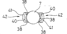
Fig. 4 is another many types of routine structural map of the handle component in the sample container turning apparatus shown in Figure 1;
Fig. 5 is the key diagram of expression 2 sample container turning apparatus phase one of embodiment of the invention operating state;
Fig. 6 is the key diagram of expression sample container turning apparatus subordinate phase operating state shown in Figure 5;
Fig. 7 is the key diagram of expression sample container turning apparatus phase III operating state shown in Figure 5.
Among the figure, 1-sample receiver, 2-specimen mounting (holding member), the 3-arm member, 4-rotary part, 5-handle component, the 6-vessel, 7-lid, 8-bindiny mechanism, 9-first driving mechanism, 10-second driving mechanism, 11-control gear, the 12-handgrip, 13-rotation axis, 14-spindle unit, the 15-cylinder, 20-travelling belt (intermittently travel mechanism), 22-motor, the 26-web joint, 30-cylinder, 36-hinge axis, the 37-hinge axis, 39,42, the 46-handgrip, the 45-handle component, the 47-rotation axis, 48, the 49-hinge axis, the 50-slotted hole, the 51-moving-member, 52-rubber ring, 53-web joint.
Below, with reference to two embodiment shown in the drawings the present invention is described, certainly, the present invention is not limited to this two embodiment.
Embodiment 1:
Among Fig. 1, sample container turning apparatus P
1Be provided with: the specimen mounting 2 that several sample receivers 1 is generally perpendicularly being kept as holding member, intermittent conveyor 20 as travel mechanism at intermittence, be configured in to approximate horizontal the arm member 3 of sample receiver 1 top, the rotary part 4 that is installed in arm member 3 left end downsides and can rotates around vertical rotating shaft, with rotary part 4 coaxial installations and with the handle component 5 of rotary part 4 rotation, be connected the bindiny mechanism 8 on the handle component 5, make first driving mechanism 9 of handle component 5 rotations by bindiny mechanism 8, make second driving mechanism 10 and control first driving mechanism 9 of rotary part 4 rotations, the control gear 11 of second driving mechanism 10.
Travelling belt 20 intermittently moves the specimen mounting 2 that is keeping several sample receivers.Sample receiver 1 is by test tube shape vessel 6 and be embedded on these body 6 upper openings and the rubber system lid 7 of airtight this opening constitutes.Blood as analytical sample is housed in vessel 6.On vessel 6, pasting the bar-code label that writes various information.Specimen mounting 2 makes test tube keep roughly being vertical, and a row is keeping ten sample receivers.
First driving mechanism 9 is made of the cylinder 15 that is installed in below the arm member 3 substantial middle portions.The piston rod 16 of cylinder 15 moves up and down.In the upper end of piston rod 16 connector 17 is installed, link stopper 18 is installed in the lower end of piston rod 16.The air scoop 19 that the air of coming in and going out is used is installed on cylinder 15 body perisporiums.In cylinder 15 body interior the compression helical spring (state does not show) of approximate vertical is being set, when piston rod 16 is flat always by toward pressing down.
Bindiny mechanism 8 is configured in the web joint 26 of arm member 3 tops with being provided with approximate horizontal.The right-hand member of this web joint 26 is fixed on the connector 17, and left end is fixed on the vertical maintenance bar 29, and the end place that keeps right below is installed on the guide rod 28 of guiding part 27.Keep bar 29 to embed vertical spindle unit 14, this spindle unit 14 runs through rotary part 4 and can move back and forth up and down.When the piston rod 16 of first driving mechanism 9 moved up and down, the web joint 26 of bindiny mechanism 8 was moved up and down by guide rod 28 guiding.As shown in Figure 1, when web joint 26 arrived upper/lower positions, the handgrip 12,12 of handle component 5 was maximum open state.
Among Fig. 1,34 for rotation testing agency, is made of switch portion 32 and test section 33.This rotation testing agency 34 is used for when the rotation of rotary part 4 stops going up the mechanism that stipulates its stop position.The 35th, bar-code reader.Read the code of the bar-code label on the vessel 6 that is attached to sample receiver 1 by this bar-code reader 35.
Below, the action of this sample container turning apparatus P1 is described.
Among Fig. 1, keeping the specimen mounting 2 of sample receiver 1 to be transmitted and be with 20 to move off and on, stopping at and give allocation (rotary part 4 under).Then, start first driving mechanism 9, its driving force sends handle component 5 to by the spindle unit 14 of bindiny mechanism 8.So two handgrips 12,12 of handle component 5 just rotate to the direction near the lid 7 of a sample receiver 1 around rotation axis 13,13, catch this lid 7 after becoming closure state.
Here, as mentioned above, the structure of handle 5 is such, that is, when two handgrips 12,12 were caught the lid 7 of a sample receiver 1, handle component turned to the narrow more position of the forward more end of distance between its handgrip 12,12 always, and lid is rubber system.Therefore, as shown in Figure 2, when handgrip 12,12 is caught when covering 7, when this covers 7 elastic deformations, handle component 5 turns to the narrow more position of the forward more end of distance between its handgrip 12,12 always, and the container that makes this sample receiver 1 leave specimen mounting 2 slightly keeps face (for example 1-2mm).
Then, the motor 22 of starting second driving mechanism 10 under this state makes rotary part 4 rotate a circle toward positive dirction.In order to read bar code, this rotational speed for example is 3-7 commentaries on classics second one.Caught and covered 7 handle component 5, its sample receiver 1 is just changeed around axis by covering 7 with rotary part 4 rotations.By the just commentaries on classics of this sample receiver 1, read the code that is attached to the bar-code label on sample receiver 1 vessel 6 by bar-code reader 35.In addition, consider that bar-code label is sometimes partly rolled or situation former thereby that can not read such as pulled bad by specimen mounting 2, make sample receiver 1 after just changeing again toward circling in the other direction, so that read bar code once more.
In this sample container turning apparatus P1, as mentioned above, caught by handle component 5 and to cover 7 sample receiver 1 and keep carrying out rotating under the come-up state of face breaking away from specimen mounting 2 containers slightly.Therefore, do not have frictional resistance between sample receiver 1 and the specimen mounting 2, the rotation of sample receiver 1 is smooth.Therefore,,, also can be effectively the driving force in the source of driving be passed to sample receiver 1, sample receiver 1 is fully rotated even adopt the drive source of little torque according to this sample container turning apparatus P1, thus realize sample container turning apparatus small-sized, oversimplify.
The handgrip 12,12 of the handle component 5 of this sample container turning apparatus P1 is made by aluminium alloy.The face of handgrip 12,12 inboards is made level and smooth curved surface.But can not adopt handgrip 12,12 as shown in Figure 3 yet, and adopt the aluminium alloy system handgrip 39,39 that respectively forms three pods 38,38,38 at medial surface.Perhaps, also can not adopt handgrip 12,12 as shown in Figure 4, and adopt handgrip 42,42, this handgrip the 42, the 42nd forms above the support 41,41 by being bonded in interior and rubber system crawl section 40,40 that respectively form three pods 38,38,38.In this case, not only can catch more securely and cover 7, and can prevent to cover 7 and stick together with handgrip 39,39,42,42.
Embodiment 2:
Among Fig. 5, sample container turning apparatus P2 is provided with: the specimen mounting 2 that several sample receivers are generally perpendicularly being kept, travelling belt 20, arm member 3, rotary part 4, with rotary part 4 coaxial installations and with the handle component 45 of rotary part 4 rotations, the bindiny mechanism 8 that is connected with handle component 45, make first driving mechanism 9 of handle component 45 rotations, second driving mechanism 10 and the control gear 11 that rotary part 4 is rotated by this bindiny mechanism 8.
Handle component 45 has two handgrips 46,46 that disposing in opposite directions, rotate with rotary part 4 coaxial installations and with rotary part 4, in order to make its handgrip 46,46 catch and decontrol the lid 7 of sample receiver 1, handle component 45 can rotate up and down around horizontal rotating shaft 47,47.Handle component 45 also is provided with oval slotted hole 50 and tabular moving-member 51.Each rotation axis 47 is embedded in also can be movable in slotted hole in this slotted hole 50.14 one-tenth of the spindle units of tabular moving-member 51 and bindiny mechanism 8 are whole, make each handgrip 46 when grasping directions and rotate when this spindle unit 14 moves, and this tabular moving-member 51 makes each handgrip 46 move by the moving direction of slotted hole 50 toward spindle units 14.
Handle component 45 also is provided with the two kinds of hinge axis 48,49 that are parallel to rotation axis 47,47.These two kinds of hinge axis 48,49 are installed on two summaries in the front and back ovalize web joint 53.Near the hinge axis 49 of moving-member 51 be installed in 51 one-tenths whole parts of bearingss of moving-member (scheming not show) on.Owing to be provided with two hinge axis 48,49 and rotation axis 47,47, handle component 45 is propped up by pivot, so that make two handgrips 46,46 catch the lid 7 of sample receiver 1.
Each end of moving-member 51 upper face sides and an end of two web joints 53 join.At each rotation axis 47 with near on its each hinge axis 48, open and establishing two rubber rings 52 in front and back.Total certain distance that keeps between these rubber rings 52 and each rotation axis 47 and close its each hinge axis 48.
Below, the action of this sample container turning apparatus P2 is described.
Among Fig. 5, keeping the specimen mounting 2 of sample receiver 1 to be transmitted and be with 20 to move off and on, stopping at and give allocation (rotary part 4 under).Then, start first driving mechanism 9, its driving force is delivered to handle component 45 by the spindle unit 14 of bindiny mechanism 8.So two handgrips 46,46 of handle component 45 just rotate towards the direction near the lid 7 of a sample receiver 1 around rotation axis 47,47, become closure state and catch this lid 7.
Then, as shown in Figure 7, under this state, the spindle unit 14 of bindiny mechanism 8 further rises under 9 effects of first driving mechanism.The moving-member 51 of handle component 45 is connected the spindle unit 14 of mechanism 8 and pulls on, and web joint 53 also rises thereupon.So owing to have the slotted hole 50 that each rotation axis 47 is embedded movably, each handgrip 46 is up carried along with the rising of web joint 53.Like this, the container that makes sample receiver 1 leave specimen mounting 2 more keeps face (for example 3-4mm).When each rotation axis 47 was positioned at slotted hole 50 lower end positions, each handgrip 46 was just no longer up carried.At this moment, each rubber ring 52 is the state that is stretched.
Then, the motor 22 of starting second driving mechanism 10 under this state makes rotary part 4 circle toward positive dirction, and the about 3-7 of its rotational speed circles second.Caught and covered 7 handle component 45, sample receiver 1 is just changeed around axis by covering 7 with rotary part 4 rotations.By the just commentaries on classics of such sample receiver 1, read the code that is attached to the bar-code label on sample receiver 1 vessel 6 by bar-code reader 35.Consider and partly roll because of bar-code label sometimes or scratched etc. former by specimen mounting 2 thereby can not read the situation of code, institute so that sample receiver 1 just changeing after counter again circling.
As mentioned above, sample receiver 1 carries out rotating under the come-up state of the container maintenance face that leaves specimen mounting 2.Therefore, do not have frictional resistance between sample receiver 1 and the specimen mounting 2, the rotation of sample receiver 1 is smooth.
After sample receiver 1 rotates a circle toward positive and negative two directions, stop the motor 22 of second driving mechanism 10.The piston rod 16 of first driving mechanism 9 drops to upper/lower positions, and the handgrip 46,46 of handle component 45 leaves the lid 7 of the sample receiver 1 that rotation finishes by bindiny mechanism 8.Then, the sample receiver 1 of rotation end is transmitted by specimen mounting 2 and is with 20 to move off and on.
As mentioned above, in this sample container turning apparatus P2, caught to cover under 7 sample receiver 1 keeps face at the container that leaves specimen mounting 2 the come-up state by handle component 45 and carry out rotating.Therefore, do not have frictional resistance between sample receiver 1 and the specimen mounting 2, the rotation of sample receiver 1 is smooth.Therefore,,, also the revolving force of drive source can be passed to sample receiver effectively, make sample receiver not have the branch rotation, can realize miniaturization, the simplification of sample container turning apparatus even adopt the drive source of little torque according to this sample container turning apparatus P2.
Here, as mentioned above, handle component 45 has such structure, that is, when two handgrips 46,46 were caught the lid 7 of a sample receiver 1, handle component 45 turned to the narrow more position of the forward more end of distance between the handgrip 46,46 always.And covering 7 is rubber systems.Therefore, as shown in Figure 6, when handgrip 46,46 is caught when covering 7, when this covers 7 elastic deformations, handle component 45 turns to the narrow more position of the forward more end of distance that makes between its handgrip 46,46 always, and the container that makes sample receiver 1 break away from specimen mounting 2 slightly keeps face (for example 1-2mm).
The handgrip the 46, the 46th of the handle component 45 of this sample container turning apparatus P2, aluminium alloy is done, and the medial surface of handgrip 46,46 is level and smooth curved surface.But also can not adopt such handgrip 46,46, and as adopting handgrip 39,39 or employing handgrip 42,42 as shown in Figure 4 as shown in Figure 3.In this case, not only can catch more securely and cover 7, and can also prevent to cover 7 and stick together with handgrip 39,39,42,42.
The present invention is owing to have above-mentioned structure, sample receiver is not crimped on the holding member not resembling in the past, so, promptly use the power source of little torque also can pass to sample receiver to the revolving force of drive source effectively, can provide small-sized and simple sample container turning apparatus.
Claims (15)
1. sample container turning apparatus, this whirligig comprises: make several sample receivers remain on the holding member of certain orientation; The travel mechanism at intermittence that this holding member is intermittently moved; Arm member; Be rotatably installed in the rotary part on this arm member; Be installed on this rotary part and have and be used to catch or decontrol a sample receiver and the handle component of several handgrips that the moving axis that can rotate rotates; Be connected with this handle component and the bindiny mechanism of running through the spindle unit that rotary part can move back and forth arranged; Move back and forth first driving mechanism that handle component is rotated by the spindle unit that makes this bindiny mechanism; Make second driving mechanism of rotary part rotation; Control the control gear of first driving mechanism and second driving mechanism, it is characterized in that:
Described handle component rotates by first driving mechanism and bindiny mechanism, and its several handgrips are caught a sample receiver, and rotary part is rotated by second drive mechanism then, and this sample receiver is rotated around axis.
2. sample container turning apparatus as claimed in claim 1 is characterized in that said sample receiver is made of a vessel.
3. sample container turning apparatus as claimed in claim 1 is characterized in that said sample receiver is made of the lid that a vessel and is located at the vessel upper shed.
4. sample container turning apparatus as claimed in claim 1 is characterized in that said holding member is a specimen mounting, is used for generally perpendicularly keeping some sample receivers to become a row.
5. sample container turning apparatus as claimed in claim 1 is characterized in that, travel mechanism one was used for mounting thereon and transmitted the conveyer of said holding member off and on said intermittence.
6. sample container turning apparatus as claimed in claim 1 is characterized in that, said arm member disposes in general horizontal direction above said holding member, so that generally perpendicularly keep sample receiver.
7. sample container turning apparatus as claimed in claim 1, it is characterized in that, said handle component comprises two handgrips that rotate at above-below direction roughly around the hinge axis of approximate horizontal, when they grasp a said sample receiver, just turn to two narrow more positions of the forward more end of the distance between the handgrip together.
8. sample container turning apparatus as claimed in claim 1, it is characterized in that, said handle component comprises slotted hole and the moving-member for the movable embedding of described rotation axis, the spindle unit of said moving-member and bindiny mechanism is in aggregates, and when this spindle unit made the past extracting of handgrip direction mobile rotationally, this moving-member made handgrip move by the moving direction of said slotted hole toward spindle unit.
9. sample container turning apparatus as claimed in claim 1 is characterized in that the spindle unit of said bindiny mechanism generally perpendicularly moves back and forth.
10. sample container turning apparatus as claimed in claim 1 is characterized in that, said first driving mechanism comprises that one is arranged at the cylinder on the said arm member.
11. sample container turning apparatus as claimed in claim 1 is characterized in that, said second driving mechanism comprises a rotation transmission member that is arranged at the motor on the said arm member and is used to transmit said motor rotation.
12. sample container turning apparatus as claimed in claim 1 is characterized in that, the rotation of said rotary part can positive and negative direction be switched by said second driving mechanism.
13. sample container turning apparatus as claimed in claim 1 is characterized in that, said control gear comprises microcomputer, RAM and ROM.
14. sample container turning apparatus as claimed in claim 1, it is characterized in that, the handgrip inboard of sample receiver or handle component is made of elastomeric element, handle component is rotated by first driving mechanism and bindiny mechanism, when its several handgrips are caught a sample receiver, in the time of with above-mentioned elastomeric element elastic deformation, the distance that handle component turns between its several handgrips always is the narrow more position of forward more end.
15. sample container turning apparatus as claimed in claim 1, it is characterized in that, handle component is provided with slotted hole and the moving-member that embeds movably for above-mentioned rotation axis, it is whole that this moving-member becomes with the spindle unit of bindiny mechanism, when this spindle unit moves so that make handgrip when grasping direction and rotate, this moving-member makes handgrip move by the moving direction of above-mentioned slotted hole towards spindle unit; Rotated by first driving mechanism and bindiny mechanism and catch the lid of a sample receiver with the handgrip of shank spare, further by the action of moving-member, handle component is keeping its sample receiver ground that it is up carried.
Applications Claiming Priority (2)
| Application Number | Priority Date | Filing Date | Title |
|---|---|---|---|
| JP203467/93 | 1993-08-17 | ||
| JP20346793A JP3347407B2 (en) | 1993-08-17 | 1993-08-17 | Sample container rotating device |
Publications (2)
| Publication Number | Publication Date |
|---|---|
| CN1111353A CN1111353A (en) | 1995-11-08 |
| CN1047001C true CN1047001C (en) | 1999-12-01 |
Family
ID=16474620
Family Applications (1)
| Application Number | Title | Priority Date | Filing Date |
|---|---|---|---|
| CN94115403A Expired - Fee Related CN1047001C (en) | 1993-08-17 | 1994-08-17 | Sample container turning apparatus |
Country Status (7)
| Country | Link |
|---|---|
| US (1) | US5455006A (en) |
| EP (1) | EP0639774B1 (en) |
| JP (1) | JP3347407B2 (en) |
| KR (1) | KR950006464A (en) |
| CN (1) | CN1047001C (en) |
| DE (1) | DE69417820T2 (en) |
| TW (1) | TW260745B (en) |
Families Citing this family (41)
| Publication number | Priority date | Publication date | Assignee | Title |
|---|---|---|---|---|
| WO1996001994A1 (en) * | 1994-07-11 | 1996-01-25 | Tekmar Company | Modular vial autosampler |
| US5948360A (en) | 1994-07-11 | 1999-09-07 | Tekmar Company | Autosampler with robot arm |
| US5551828A (en) * | 1994-10-27 | 1996-09-03 | Abbott Laboratories | Container mover and method of moving a container |
| US5772962A (en) * | 1995-05-29 | 1998-06-30 | Hitachi, Ltd. | Analyzing apparatus using disposable reaction vessels |
| EP0899572A4 (en) * | 1996-05-01 | 2005-02-02 | Sanko Junyaku Kk | Automatic immunoassay method and apparatus |
| US5804697A (en) * | 1997-02-24 | 1998-09-08 | The United States Of America As Represented By The Secretary Of The Air Force | Remote control structural exciter |
| FR2764704B1 (en) * | 1997-06-16 | 1999-08-20 | Stago Diagnostica | DEVICE FOR THE AUTOMATIC READING OF AN IDENTIFICATION CODE CARRIED BY TUBULAR CONTAINERS |
| ES2133129B1 (en) * | 1997-11-19 | 2000-05-01 | Grifols Grupo Sa | APPARATUS FOR THE AUTOMATIC PERFORMANCE OF LABORATORY TESTS. |
| AR017411A1 (en) * | 1997-11-19 | 2001-09-05 | Grifols Sa | APPLIANCE FOR THE AUTOMATIC PERFORMANCE OF LABORATORY TESTS |
| AUPP058197A0 (en) * | 1997-11-27 | 1997-12-18 | A.I. Scientific Pty Ltd | Pathology sample tube distributor |
| US6562299B1 (en) * | 1998-09-18 | 2003-05-13 | Cytyc Corporation | Method and apparatus for preparing cytological specimens |
| NZ510255A (en) * | 2001-02-28 | 2003-01-31 | Intellitech Automation Ltd | sample preparation apparatus, typically for milk sampling, with double pivoting robotic arm |
| DE10247731B4 (en) * | 2002-10-12 | 2007-04-12 | Eppendorf Ag | Gripping tool, dosing tool and tool holder for a laboratory automat |
| JP3803347B2 (en) * | 2004-02-19 | 2006-08-02 | 株式会社アイディエス | Preparative dispensing equipment |
| JP3860178B2 (en) * | 2004-04-05 | 2006-12-20 | 株式会社アイディエス | Bar code reader for test tubes |
| US7855077B2 (en) * | 2006-09-29 | 2010-12-21 | Beckman Coulter, Inc. | Method and device for test sample loading |
| ES2341574T3 (en) * | 2006-12-04 | 2010-06-22 | Inpeco Ip Ltd | DEVICE OF TURN OF CARRIER FOR A CARRIER OF CARRIER. |
| US8429954B2 (en) * | 2007-03-12 | 2013-04-30 | Purdue Research Foundation | Monolithic comb drive system and method for large-deflection multi-DOF microtransduction |
| US7721587B2 (en) * | 2007-03-12 | 2010-05-25 | Purdue Research Foundation | System and method for improving the precision of nanoscale force and displacement measurements |
| US9164113B2 (en) * | 2009-08-07 | 2015-10-20 | Siemens Healthcare Diagnostics Inc. | Methods, systems, and apparatus adapted to transfer sample containers |
| JP2011185628A (en) * | 2010-03-05 | 2011-09-22 | Sysmex Corp | Sample analyzer, method of obtaining sample identification information, and sample identification information obtaining apparatus |
| EP2455761B1 (en) | 2010-11-23 | 2018-08-08 | Hach Lange GmbH | Method for detecting an optical marking on a laboratory analysis vessel |
| EP2538227B1 (en) * | 2011-06-20 | 2015-02-18 | F. Hoffmann-La Roche AG | Device for decapping and recapping sample tubes |
| US9381524B2 (en) | 2011-11-08 | 2016-07-05 | Becton, Dickinson And Company | System and method for automated sample preparation |
| CN104736439A (en) | 2012-10-16 | 2015-06-24 | 贝克曼考尔特公司 | Container fill level detection |
| JP6336715B2 (en) * | 2013-05-30 | 2018-06-06 | 富士レビオ株式会社 | Grip mechanism |
| JP6247953B2 (en) * | 2014-02-14 | 2017-12-13 | 株式会社日立ハイテクノロジーズ | Sample processing system |
| JP6419540B2 (en) * | 2014-11-14 | 2018-11-07 | シスメックス株式会社 | Sample measuring apparatus and sample measuring method |
| US10288633B2 (en) | 2015-06-26 | 2019-05-14 | Abbott Laboratories | Reaction vessel moving member for moving reaction vessels from a processing track to a rotating device in a diagnostic analyzer |
| CN108027379B (en) | 2015-06-26 | 2021-07-23 | 雅培实验室 | Reaction vessel exchange device for diagnostic analysis apparatus |
| EP3385719B1 (en) * | 2015-12-15 | 2022-04-27 | HORIBA, Ltd. | Device for rotating an object |
| CN105645308A (en) * | 2016-01-25 | 2016-06-08 | 浙江海洋学院 | Resistance storage device |
| GB2551991A (en) * | 2016-07-04 | 2018-01-10 | Stratec Biomedical Ag | Device for handling vials |
| CN106959375B (en) * | 2017-05-13 | 2018-05-22 | 遵义医学院附属医院 | A kind of sample injection bottle automatic mixing pulls out lid arrangement |
| KR102374895B1 (en) * | 2017-05-22 | 2022-03-17 | 주식회사 만도 | Fuse pad, printed circuit board including the fuse pad and method for manufacturing thereof |
| KR101796187B1 (en) * | 2017-05-31 | 2017-11-10 | 동문이엔티(주) | Distillation system decomposition tube lifting device |
| CN107132364B (en) * | 2017-06-02 | 2018-09-07 | 迈克医疗电子有限公司 | Information read device and sample analyser |
| JP7254105B2 (en) * | 2018-06-28 | 2023-04-07 | バイオ-ラッド・ラボラトリーズ・インコーポレーテッド | Container rotating device and container rotating method |
| DE102019108767A1 (en) * | 2019-01-11 | 2020-07-16 | Hti Bio-X Gmbh | Gripping device for gripping lids for laboratory vessels |
| CN112722811B (en) * | 2020-12-25 | 2022-04-29 | 珠海丽珠试剂股份有限公司 | Reaction vessel conveying device and reaction vessel supplementing equipment using same |
| IT202100028421A1 (en) | 2021-11-09 | 2023-05-09 | Gimatic S R L | Motorized gripper for industrial manipulators |
Family Cites Families (11)
| Publication number | Priority date | Publication date | Assignee | Title |
|---|---|---|---|---|
| DE1287704B (en) * | 1965-03-24 | 1969-01-23 | ||
| US4582990A (en) * | 1980-10-27 | 1986-04-15 | Randam Electronics, Inc. | Analytical instrument with two moving trains of sample holder-carrying trays under microprocessor control |
| US4478095A (en) * | 1981-03-09 | 1984-10-23 | Spectra-Physics, Inc. | Autosampler mechanism |
| US4595562A (en) * | 1981-07-20 | 1986-06-17 | American Hospital Supply Corporation | Loading and transfer assembly for chemical analyzer |
| US4835707A (en) * | 1986-07-23 | 1989-05-30 | Takeda Chemical Industries, Ltd. | Automatic analysis method and apparatus for enzyme reaction |
| US4951512A (en) * | 1988-06-23 | 1990-08-28 | Baxter International Inc. | System for providing access to sealed containers |
| US5008082A (en) * | 1988-08-25 | 1991-04-16 | Eastman Kodak Company | Analyzers using linear sample trays with random access |
| US4927545A (en) * | 1988-10-06 | 1990-05-22 | Medical Automation Specialties, Inc. | Method and apparatus for automatic processing and analyzing of blood serum |
| US5209903A (en) * | 1989-09-06 | 1993-05-11 | Toa Medical Electronics, Co., Ltd. | Synthetic apparatus for inspection of blood |
| TW199858B (en) * | 1990-03-30 | 1993-02-11 | Fujirebio Kk | |
| JPH0736284Y2 (en) * | 1990-10-05 | 1995-08-16 | 東亜医用電子株式会社 | Sample identification code reader for sample container |
-
1993
- 1993-08-17 JP JP20346793A patent/JP3347407B2/en not_active Expired - Fee Related
-
1994
- 1994-06-06 TW TW083105117A patent/TW260745B/zh active
- 1994-08-12 US US08/289,561 patent/US5455006A/en not_active Expired - Fee Related
- 1994-08-16 EP EP94401857A patent/EP0639774B1/en not_active Expired - Lifetime
- 1994-08-16 DE DE69417820T patent/DE69417820T2/en not_active Expired - Fee Related
- 1994-08-16 KR KR1019940020084A patent/KR950006464A/en active IP Right Grant
- 1994-08-17 CN CN94115403A patent/CN1047001C/en not_active Expired - Fee Related
Also Published As
| Publication number | Publication date |
|---|---|
| US5455006A (en) | 1995-10-03 |
| DE69417820T2 (en) | 1999-10-07 |
| JP3347407B2 (en) | 2002-11-20 |
| DE69417820D1 (en) | 1999-05-20 |
| CN1111353A (en) | 1995-11-08 |
| EP0639774B1 (en) | 1999-04-14 |
| KR950006464A (en) | 1995-03-21 |
| EP0639774A1 (en) | 1995-02-22 |
| TW260745B (en) | 1995-10-21 |
| JPH0755814A (en) | 1995-03-03 |
Similar Documents
| Publication | Publication Date | Title |
|---|---|---|
| CN1047001C (en) | Sample container turning apparatus | |
| US9446911B2 (en) | Apparatus for transferring reaction receptacles between a plurality of receptacle-receiving structures | |
| CN1667417A (en) | Apparatus for sensing coagulation of blood sample | |
| CN107022965B (en) | A kind of rubbish is picked up and sorter | |
| CN105556315B (en) | Test piece takes mechanism, test piece mobile device, liquid sample analyzer and test piece and takes method | |
| CN1254673A (en) | Card separator and distributor | |
| CN211079172U (en) | System for centering circular objects | |
| CN109911598A (en) | Code-reading apparatus and feed bin with it | |
| CN207090392U (en) | A kind of defective products sorting equipment | |
| JPH0755815A (en) | Sample container rotary unit | |
| CN1100529A (en) | Film developing device | |
| CN210706584U (en) | Automatic page turning mechanism and scanning equipment | |
| CN213320182U (en) | Picking structure of sorting robot | |
| CN108217555A (en) | A kind of hood-opening device of sample container | |
| CN211444974U (en) | Sample rotary uncovering mechanism | |
| CN107796935A (en) | POCT test cards Bidirectional conveying device, gynaecology's joint inspection instrument and its method of work | |
| CN207138313U (en) | Sorting equipment | |
| CN218230892U (en) | Test tube device of uncapping and sample pretreatment system | |
| CN220722717U (en) | Test tube loading attachment | |
| CN213689424U (en) | Multicolor ID trademark printing quality defect detection system | |
| JP3790330B2 (en) | Syringe visual inspection method and apparatus thereof | |
| CN213737328U (en) | Cup arranging device | |
| US20220299538A1 (en) | Apparatus for removing a cap closing a laboratory sample container and laboratory automation system | |
| CN220766465U (en) | Protein split charging equipment | |
| CN112660752A (en) | Cup arranging device |
Legal Events
| Date | Code | Title | Description |
|---|---|---|---|
| C06 | Publication | ||
| PB01 | Publication | ||
| C10 | Entry into substantive examination | ||
| SE01 | Entry into force of request for substantive examination | ||
| C14 | Grant of patent or utility model | ||
| GR01 | Patent grant | ||
| C19 | Lapse of patent right due to non-payment of the annual fee | ||
| CF01 | Termination of patent right due to non-payment of annual fee |