CN1042620C - Output apparatus - Google Patents
Output apparatus Download PDFInfo
- Publication number
- CN1042620C CN1042620C CN93118631A CN93118631A CN1042620C CN 1042620 C CN1042620 C CN 1042620C CN 93118631 A CN93118631 A CN 93118631A CN 93118631 A CN93118631 A CN 93118631A CN 1042620 C CN1042620 C CN 1042620C
- Authority
- CN
- China
- Prior art keywords
- housing
- transfer device
- load transfer
- spiral propeller
- space
- Prior art date
- Legal status (The legal status is an assumption and is not a legal conclusion. Google has not performed a legal analysis and makes no representation as to the accuracy of the status listed.)
- Expired - Fee Related
Links
Images


Classifications
-
- B—PERFORMING OPERATIONS; TRANSPORTING
- B65—CONVEYING; PACKING; STORING; HANDLING THIN OR FILAMENTARY MATERIAL
- B65G—TRANSPORT OR STORAGE DEVICES, e.g. CONVEYORS FOR LOADING OR TIPPING, SHOP CONVEYOR SYSTEMS OR PNEUMATIC TUBE CONVEYORS
- B65G33/00—Screw or rotary spiral conveyors
- B65G33/24—Details
- B65G33/26—Screws
- B65G33/30—Screws with a discontinuous helical surface
-
- B—PERFORMING OPERATIONS; TRANSPORTING
- B65—CONVEYING; PACKING; STORING; HANDLING THIN OR FILAMENTARY MATERIAL
- B65G—TRANSPORT OR STORAGE DEVICES, e.g. CONVEYORS FOR LOADING OR TIPPING, SHOP CONVEYOR SYSTEMS OR PNEUMATIC TUBE CONVEYORS
- B65G53/00—Conveying materials in bulk through troughs, pipes or tubes by floating the materials or by flow of gas, liquid or foam
- B65G53/04—Conveying materials in bulk pneumatically through pipes or tubes; Air slides
- B65G53/28—Systems utilising a combination of gas pressure and suction
-
- B—PERFORMING OPERATIONS; TRANSPORTING
- B01—PHYSICAL OR CHEMICAL PROCESSES OR APPARATUS IN GENERAL
- B01F—MIXING, e.g. DISSOLVING, EMULSIFYING OR DISPERSING
- B01F35/00—Accessories for mixers; Auxiliary operations or auxiliary devices; Parts or details of general application
- B01F35/71—Feed mechanisms
- B01F35/717—Feed mechanisms characterised by the means for feeding the components to the mixer
- B01F35/7173—Feed mechanisms characterised by the means for feeding the components to the mixer using gravity, e.g. from a hopper
- B01F35/71731—Feed mechanisms characterised by the means for feeding the components to the mixer using gravity, e.g. from a hopper using a hopper
-
- B—PERFORMING OPERATIONS; TRANSPORTING
- B65—CONVEYING; PACKING; STORING; HANDLING THIN OR FILAMENTARY MATERIAL
- B65G—TRANSPORT OR STORAGE DEVICES, e.g. CONVEYORS FOR LOADING OR TIPPING, SHOP CONVEYOR SYSTEMS OR PNEUMATIC TUBE CONVEYORS
- B65G33/00—Screw or rotary spiral conveyors
- B65G33/08—Screw or rotary spiral conveyors for fluent solid materials
- B65G33/14—Screw or rotary spiral conveyors for fluent solid materials comprising a screw or screws enclosed in a tubular housing
-
- F—MECHANICAL ENGINEERING; LIGHTING; HEATING; WEAPONS; BLASTING
- F23—COMBUSTION APPARATUS; COMBUSTION PROCESSES
- F23G—CREMATION FURNACES; CONSUMING WASTE PRODUCTS BY COMBUSTION
- F23G5/00—Incineration of waste; Incinerator constructions; Details, accessories or control therefor
- F23G5/44—Details; Accessories
Abstract
The invention relates to a transporting device having a conveyor worm (3) which is rotatable about its longitudinal axis and is disposed in a housing (6) exhibiting a feed opening (7) and a discharge opening (8). It is envisaged that in one part-section of the housing (6) the conveyor worm (3) should exhibit a different pitch from elsewhere. Between the conveyor worm (3) and the housing (6, 6a - d), a by-pass space (9a - d) for relatively large component parts of the material to be transported can be present.
Description
The present invention is a load transfer device, and its spiral propelling unit can rotate around its longitudinal axis, and a shell is arranged, and inlet point and discharging opening are arranged on the housing.
The load transfer device of this pattern is that everybody is familiar with, and it is applicable to different materials.
Known load transfer device all the time a pad volume 3/4ths, stop up avoiding.
If pack catalyst chamber into and will use load transfer device for material that will be to be sent, will require: must not have air to enter catalyst chamber and (perhaps) must not have gas to come out from catalyst chamber by load transfer device by load transfer device.Such catalyst chamber can be one according to low temperature carbonization cylinder EP-0 302 310 B1, that be used in waste material heating treatment facility.At this moment, inhomogeneous waste material: as broken household garbage, the industrial refuse of fritter, and partly solidified accretion etc., all enter the low temperature carbonization cylinder by load transfer device.The low temperature carbonization process of being carried out in the low temperature carbonization cylinder can increase being interfered owing to the inlet of oxygen in the atmosphere suddenly.Aspect in addition, the low temperature carbonization gas that produces in the low temperature carbonization device is by low temperature carbonization airway feeding combustion chamber.Low temperature carbonization gas must not and enter in the surrounding environment by the delivery system backflow.
The feedway that a kind of on the go does not have gas to disturb can be made according to US-A-3 593 844.Spiral angle of rake length must not surpass the total length of housing, to cause the obstruction of convey materials.This obstruction can stop air communication to cross housing.
The obstruction that forms also can cause the obstruction of feedway.
Successfully convey materials just requires the Backlog Materiel material to adhere on the spiral propeller.In order to accomplish this point, the general practice is that baffle plate is installed on housing wall, and this plate is stretched between spiral propeller and housing.When spiral propeller rotated, the as ready material was scraped off from spiral propeller by baffle plate.
Task of the present invention is: make a kind of load transfer device, it can guarantee there is not the gaseous state thing all the time, installs through this as air or low temperature carbonization air-flow, and can not stop up.
Can finish above mentioned invention task according to the present invention, way is in a certain section of housing, and the thread density of spiral propeller is different with other place.Like this, in a certain particular segment of load transfer device, wait to send the density meeting of material fine.Owing to press very tightly, material just presses to housing, causes this a part of rate of pressurization of housing bigger.Like this, atmosphere just can not enter catalyst chamber by feedway from the outside, as: enter the low temperature carbonization burning installation.In addition, in catalyst chamber, can not produce the gas that resembles the low temperature carbonization gas, from the low temperature carbonization cylinder, come out, enter surrounding environment through load transfer device against throughput direction.The advantage of load transfer device manufactured according to the present invention is all to be air tight all the time.Because spiral propeller is an integral body of stretching to whole housing, although it seals into airtight shape, also can continue to eliminate the obstruction of load transfer device.
Example is: spiral propeller in a segmentation thread density than other places height.In this higher section of thread density, the material density of transportation is big, has formed the hermetic closed phenomenon of being made up of convey materials.
Higher this of spiral propeller thread density section, can two than low thread density section between.The material dense space that load transfer device is sealed up is positioned at one section place of load transfer device in-to-in.
The another one example is that spiral propeller has a Ullage (crack) in housing.In this space scope, material can not continue to move via spiral propeller.By first section of spiral propeller, promptly be positioned at one section of front, space, the material of reach at first is deposited in the space, thereby causes material that inner whole space, space has all been filled up until shell wall.Therefore, also just formed the air tight sealing in that place.Because the continuous supply of material, the intensive volume of material is by the space, and by being positioned at second section of the back, space and separated seeing off on the spiral propeller, and the space to face portion, intensive volume replenishes again and has gone up.In inside, space, the volume of material constantly is among the motion.This moment, it intensive as to make load transfer device be in the air tight closed state always.
According to another example, the terminal of spiral propeller is positioned at housing inner outlet distance the last period.As described in precedent, formed an intensive material district in operation.Constantly replenished owing to spiral propeller, intensive material district disintegrates in the exit.Be that with the precedent difference the hermetic closed position of load transfer device is not inner and near the outlet at housing.
According to the present invention, hermetic closed for load transfer device is formed, will progressively fill up at least, and so, intensive material just is attached on the spiral propeller, rotates with spiral propeller with material to be sent.Like this, perhaps, can cause and to continue to carry.Material rests on the phenomenon in the load transfer device.
In order to stop material along with spiral propeller rotates together, for example can be like this, promptly between the housing of spiral propeller, there is one and dodges the space, that is to say, perpendicular to outside the Y, between spiral propeller maximum radius and housing wall, there is the metric space of different sizes to exist from the longitudinal axis of spiral propeller.So just can guarantee to be sent material can between or leave spiral propeller and do not rotate with propelling unit.
Characteristics of the inventive method are not need to install baffle plate in inner walls, and it is the most common so far way that baffle plate is installed, and its objective is to stop material to rotate with spiral propeller.When this baffle plate serious wear, also can continue not have the work of wearing and tearing ground according to load transfer device of the present invention.
For example dodge the space in order to make one, the cross sections of housing is circular, and the axle of spiral propeller is that eccentric shape is installed with the housing longitudinal axis in housing.
Other example is that housing has the channel shape cross-section in bottom semicircle, four directions, top.
Another example is that the cross-sectional plane of housing is a polygon.This polygon cross-sectional plane also the bottom be that polygon, top are the channel shape cross-section of rectangle.
The effect of all these versions all is to make to be sent material not rotate with spiral propeller.
Spiral propeller can be the taper that diameter strengthens gradually according to direction of transfer in the charging door scope.When a vertical shaft, aboveground when the loadings meter is housed is arranged at charging door top, the effect of this structure is very big, if spiral propeller cross-sectional plane on its whole length all is equally big, as ready material surface can raise gradually according to throughput direction when equipment operation in the vertical shaft.So just can't carry out failure-free to loadings measures.The spiral section that is arranged in the pyramidal structure place of vertical shaft bottom has guaranteed constantly to keep a horizontal surface forever at the material of vertical shaft.This is because in the bottom of inlet point, is discharged according to the increasing material of carriage direction.At this moment could measure loadings.
The outstanding especially advantage of device manufactured according to the present invention is, do not have the gaseous state thing load transfer device of can flowing through, and no matter is the windstream of carriage direction, and still reciprocal air-flow has all been eliminated.In addition, also avoided the obstruction of load transfer device.
The structure example of this method and the feedway of material will be described further in conjunction with the accompanying drawings.
Spiral propeller has one section thread density big in Fig. 1 load transfer device
Fig. 2 spiral propeller has the load transfer device in Ullage (crack)
Fig. 3 spiral propeller terminal is at the load transfer device at one segment distance place, discharging opening front
Fig. 4 housing cross-sectional plane is the circular and eccentric load transfer device that spiral propeller is installed
Fig. 5 housing is the load transfer device of flute profile
Fig. 6 housing cross-sectional plane is polygonal load transfer device
Fig. 7 trough-shaped housing cross-sectional plane is polygonal load transfer device
The load transfer device of the spiral propeller that Fig. 8 inlet point scope is tapered
In Fig. 1,2 and 3, spiral propeller 3 transports material A, for example, will be transported to the component part low temperature carbonization cylinder 2 of low temperature carbonization-burning-equipment from the rubbish of vertical shaft 1 dress.Spiral propeller 3 can rotate around its longitudinal axis.Therefore it can be installed on the axle 4, and this axle can be by motor 5 driven rotary.Spiral propeller 3 is installed in the housing 6.Housing will have a mouth that leads to axle 4, the charging door 7 of immediate shipment material A and discharging opening 8 at least.Charging door 7 can link to each other with vertical shaft 1.Discharging opening 8 can connect low temperature carbonization cylinder 2.The material A that enters housing 6 by filler 7 will be transported to discharging opening 8 and lay down therefrom by the spiral propeller 3 that rotates.
Under certain usage condition, for example when vertical shaft 1 is delivered to low temperature carbonization cylinder 2 with rubbish, require aerial oxygen to enter low temperature carbonization cylinder 2 from inlet point 7, from low temperature carbonization cylinder 2 coming out enter by the low temperature carbonization gas of fortune rubbish in the convection current also must not enter surrounding environment by inlet point 7.
According to Fig. 1, one section 3a of spiral propeller 3, in order to stop air-flow through load transfer device, this section thread density is greater than the remainder of spiral propeller.So just can make and be sent material A intensive, and make that the entire portion space of housing 6 is filled up by material A in one section 3a scope of spiral propeller 3 in other place of parts 3a scope internal ratio.This seals into airtight conditions in that place of housing to be transferred material A.Like this, no matter be from inlet point 7 to discharging opening 8 air, still reciprocal low temperature carbonization gas all can not flow.At the rear portion of carriage direction, seal area, promptly be positioned at the scope behind one section 3a of spiral propeller 3, the thread density of spiral propeller 3 is less again.Heavy again loose by the material A heap that housing 6 entire cross section put in.In load transfer device, can not form the obstruction of material A load transfer device.
Shown in Figure 2 is spiral propeller 3 centre portion hollows.Between one section 3b of spiral propeller 3 and 3c is empty.Sent material A to be sent to hollow space, gathered and fill up the entire cross section of housing 6 there by the segmentation 3b of spiral propeller 3.By by the weighting material that sent material A to form, when the segmentation 3c of continuous material A by segmentation 3b by spiral propeller 3, separate.This moment, housing 6 was close airtight owing to transported the material A sealing.
Be according to the load transfer device of Fig. 3 and the equipment difference of Fig. 2: that section of the no spiral propeller 3 of housing 6, not at the center of housing 6, but at the discharge port end of housing 6.According to Fig. 3, the terminal of spiral propeller 3 is in discharging opening distance 8 the last period.Just filled up between the terminal of spiral propeller 3 and discharging opening 8 by the fortune material A like this, it has filled up the entire cross section of housing 6, and gets housing 6 envelopes close airtight.When material A constantly enters, during by spiral propeller 3, intensive weighting material will be in 8 piece ground fractures of discharging opening.Material A is come out from housing 6 by discharging opening 8 by this way.
Fig. 2 and (or) version of Fig. 3 and the use capable of being combined of the version of Fig. 1.
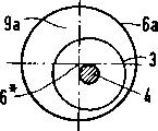
For can be with being sent material A that housing 6 is sealed into air hermetic, equipment must have good traffic capacity.Especially transport rubbish, relatively during the material A of bulk, can not be with spiral propeller 3 wedgings or obstruction, this will have one to dodge space 9a-d to those big relatively parts according to Fig. 4 to 7.When spiral propeller 3 rotated, these big relatively things to be sent are pressed into dodged space 9a-d, spiral propeller was broken avoiding.This dodges top or side that the space generally is positioned at spiral propeller 3.
According to Fig. 4, the transversal surface of housing 6a is circular, and the axle 4 of spiral propeller 3 departs from housing 6a longitudinal axis 6* in housing 6a.So, dodge space 9a just on the top of spiral propeller 3.
According to Fig. 5, the space of dodging of trough-shaped housing 6b is 9b, and this lower housing portion is semicircle, and top is rectangle.
According to Fig. 6, housing 6c cross-sectional plane is a polygon, and it dodges space 9c in the scope of shell limit.
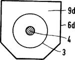
According to Fig. 7, housing 6d is become by the shell combination that is shaped as 6b and 6c.The cross-sectional plane of housing 6d is made of bottom polygon, top rectangle.Like this, dodge space 9d just in the edge extent of housing 6d.
According to Fig. 8, below inlet point 7, increase tapered gradually towards throughput direction spiral propeller 3 diameters.Below inlet point 7, will transport increasing material A like this according to throughput direction.Consequently: the material A of packing into is in horizontal surface all the time above inlet point in vertical shaft 1.Only in this way could carry out failure-free with loadings meter 10 to the loading height in the vertical shaft 1 measures.
Load transfer device of the present invention only promptly forms airtight by being transferred material A.So just can guarantee: when in being transferred material A relative bulk noncombustibility being arranged, spiral propeller 3 itself can not rupture.At last, according to Fig. 8, can in vertical shaft 1, measure loadings.
Relevant marginal data: 1 vertical shaft, 2 low temperature distillation cylinders, 3 spiral propeller 3a, 3b, segmentation 4 axles 5 motors 6 of 3c spiral propeller, the 6a-6d housing 6* housing longitudinal axis 7 charging apertures 8 discharging openings 9,9a-9d dodges space 10 and loads planar survey meter A material
Claims (9)
1, a kind of load transfer device, a spiral propeller (3) that can rotate around self longitudinal axis is arranged, the housing (6) of a band inlet point (7) and discharging opening (8) is arranged, and it is characterized by: the thread density and the other parts of its spiral propeller (3) are different in certain part of housing (6); Spiral propeller (3) is gone up bigger that section (3a) of thread density between the lower section of two thread density.
2, according to the load transfer device of claim 1, it is characterized by: between spiral propeller (3) and housing (6), dodge space (9a-d).
3, according to the load transfer device of claim 2, it is characterized by: housing (6a) for form one dodge space (9a) cross-sectional plane is made circular and spiral propeller (3) the longitudinal axis housing (6a) in and the longitudinal axis (6 of housing
*) be eccentric shape and install.
4, according to the load transfer device of claim 2, it is characterized by: housing (6b) is dodged space (9b) cross-sectional plane is made the bottom is the structure of rectangle for semicircle top for forming.
5, according to the load transfer device of claim 2, it is characterized by: dodge space (9c) for formation in the housing (6c) cross-sectional plane is made polygon.
6, according to the load transfer device of claim 5, it is characterized by: desire in housing (6d) to form and dodge space (9d) cross-sectional plane is made polygon.
7, according to the load transfer device of claim 6, it is characterized by: spiral propeller (3) increases tapered according to the throughput direction diameter in inlet point (7) scope gradually.
8, according to the load transfer device of claim 7, it is characterized by: inlet point (7) is connected with vertical shaft (1) with a load garbage.
9, load transfer device according to Claim 8 is characterized by: discharging opening (8) is connected with a low temperature carbonization cylinder.
Applications Claiming Priority (2)
| Application Number | Priority Date | Filing Date | Title |
|---|---|---|---|
| DEP4232684.2 | 1992-09-29 | ||
| DE4232684A DE4232684A1 (en) | 1992-09-29 | 1992-09-29 | Method of transportation and transportation device |
Publications (2)
| Publication Number | Publication Date |
|---|---|
| CN1086785A CN1086785A (en) | 1994-05-18 |
| CN1042620C true CN1042620C (en) | 1999-03-24 |
Family
ID=6469166
Family Applications (1)
| Application Number | Title | Priority Date | Filing Date |
|---|---|---|---|
| CN93118631A Expired - Fee Related CN1042620C (en) | 1992-09-29 | 1993-09-28 | Output apparatus |
Country Status (16)
| Country | Link |
|---|---|
| US (1) | US5558203A (en) |
| EP (1) | EP0662926B1 (en) |
| JP (2) | JPH08501522A (en) |
| KR (1) | KR100251009B1 (en) |
| CN (1) | CN1042620C (en) |
| AT (1) | ATE145621T1 (en) |
| CA (1) | CA2145637A1 (en) |
| CZ (1) | CZ286835B6 (en) |
| DE (2) | DE4232684A1 (en) |
| DK (1) | DK0662926T3 (en) |
| ES (1) | ES2095666T3 (en) |
| HU (1) | HU217600B (en) |
| PL (1) | PL171889B1 (en) |
| RU (1) | RU2117617C1 (en) |
| SK (1) | SK279640B6 (en) |
| WO (1) | WO1994007780A1 (en) |
Cited By (1)
| Publication number | Priority date | Publication date | Assignee | Title |
|---|---|---|---|---|
| CN109923049A (en) * | 2016-09-29 | 2019-06-21 | 威埃姆集团股份有限公司 | Screw conveyor for conveying powdered material especially cement etc. |
Families Citing this family (26)
| Publication number | Priority date | Publication date | Assignee | Title |
|---|---|---|---|---|
| DE4420976C2 (en) * | 1994-06-16 | 1997-02-06 | Voith Sulzer Stoffaufbereitung | Method and device for the controlled transport of thickened fibrous material from a pressurized space |
| DE4427180A1 (en) * | 1994-08-01 | 1996-02-08 | Siemens Ag | Method of sealing carbonisation chamber for soft coking or pyrolysis |
| DE9417092U1 (en) * | 1994-10-27 | 1995-11-30 | Hosokawa Alpine Ag | Material feed for material bed roller mills |
| DE10139947A1 (en) * | 2001-08-21 | 2003-03-06 | Kloeckner Haensel Proc Gmbh | Method and device for the continuous delivery of confectionery masses |
| JP4725712B2 (en) * | 2005-01-25 | 2011-07-13 | オヤマダエンジニアリング株式会社 | Solid fuel combustion equipment |
| DE102005059856A1 (en) * | 2005-12-15 | 2007-06-28 | Nill-Tech Gmbh | Conveyor and sluice system for use in conveyance of poured goods, consists of worm screw shaft that two windings |
| US7732718B2 (en) * | 2008-05-09 | 2010-06-08 | Ishida Co., Ltd. | Combination weighing apparatus with conveying unit including trough and spiral member |
| DE102008026835A1 (en) | 2008-06-05 | 2009-12-17 | Kurt Himmelfreundpointner | Conveyable material e.g. foam particle feeding method for shaft furnace in cement production, involves conveying air or gas into starting region of lance through mechanical conveyor operating at zero pressure |
| DE102008026836B4 (en) | 2008-06-05 | 2010-04-08 | Kurt Himmelfreundpointner | Method and device for conveying material through a furnace wall |
| KR20100138809A (en) * | 2009-06-24 | 2010-12-31 | 도시바 기카이 가부시키가이샤 | Conveyer apparatus of metal cutting chip |
| JP2011191040A (en) * | 2010-03-16 | 2011-09-29 | Yamamoto Co Ltd | Woody pellet combustion device |
| CN102942941B (en) * | 2012-11-09 | 2014-10-29 | 陆正明 | Biomass distillation and power generation system |
| DE102012111050A1 (en) * | 2012-11-16 | 2014-05-22 | Thyssenkrupp Resource Technologies Gmbh | Multi-level furnace and process for the thermal treatment of a material flow |
| CN103411211B (en) * | 2013-08-30 | 2016-10-19 | 厦门中科城环新能源有限公司 | It is suitable for biomass and the fluidized bed gasification combustion boiler of dangerous solid waste |
| KR20150002350U (en) * | 2013-12-10 | 2015-06-18 | 주식회사 인선리싸이클 | extruder for recycling machine of waste polyurethan |
| BE1022112B1 (en) * | 2014-02-12 | 2016-02-16 | Cnh Industrial Belgium Nv | HARVESTER |
| DE102015002770A1 (en) * | 2015-03-05 | 2016-09-08 | Schenck Process Gmbh | Apparatus and method for conveying bulk material into a pressure chamber |
| CN105000337A (en) * | 2015-07-28 | 2015-10-28 | 无锡锡东能源科技有限公司 | Loading plunger type screw feeder |
| CN106672980B (en) * | 2015-11-06 | 2022-03-04 | 岳阳高圭新材料有限公司 | Screw conveying reactor and method for continuously producing low-impurity magnesium silicide |
| CN106672978B (en) * | 2015-11-06 | 2019-07-09 | 岳阳高圭新材料有限公司 | The technique of magnesium silicide combination method continuous closed-loop production silane and polysilicon |
| CN105351956B (en) * | 2015-11-30 | 2018-03-20 | 桃江县琼宇生物质成型能料厂 | A kind of boiler preparation hopper |
| CN106089255A (en) * | 2016-08-22 | 2016-11-09 | 岳双喜 | New type pressurized formula powder accelerator adding set |
| CN108689184B (en) * | 2018-06-05 | 2024-03-22 | 深圳市一胜百机械设备制造有限公司 | Vertical powder feeder |
| SE542327C2 (en) * | 2018-08-31 | 2020-04-14 | Valmet Oy | A screw feeder and a pipe to be used in a screw feeder |
| CN109573492B (en) * | 2018-11-15 | 2021-01-26 | 山东理工大学 | Multi-shaft spiral conveying device |
| WO2024036159A1 (en) * | 2022-08-09 | 2024-02-15 | Dow Global Technologies Llc | Advanced visco-seals for single screw extruders |
Citations (4)
| Publication number | Priority date | Publication date | Assignee | Title |
|---|---|---|---|---|
| GB443372A (en) * | 1934-06-26 | 1936-02-24 | Henry Morgan Brooks | Improvements in coal stokers |
| US2465145A (en) * | 1947-04-04 | 1949-03-22 | Wilbur G Brainerd | Demountable conveyer trough |
| US3107825A (en) * | 1961-06-02 | 1963-10-22 | Paul W Sindlinger | Variable flow feed auger for delivering from sealed storage bins |
| US4036411A (en) * | 1975-09-26 | 1977-07-19 | Sos Consolidated, Inc. | Low profile auger and hopper assembly |
Family Cites Families (44)
| Publication number | Priority date | Publication date | Assignee | Title |
|---|---|---|---|---|
| SE141151C1 (en) * | ||||
| CH201148A (en) * | 1937-03-03 | 1938-11-15 | Hannoversche Maschinenbau Akti | Auger. |
| GB509721A (en) * | 1938-02-09 | 1939-07-20 | Internat Unicalor Company Ltd | Improvements in underfeed stokers of the screw type |
| GB576688A (en) * | 1940-10-02 | 1946-04-16 | Christian Oskar Rasmussen | Improvements in screw conveyor devices for charging coal distillation chambers |
| GB569370A (en) * | 1942-06-20 | 1945-05-22 | American Defibrator | Improvements in apparatus for the production of wood or like fibrous pulp |
| GB850699A (en) * | 1957-11-25 | 1960-10-05 | Central Electr Generat Board | Improvements in or relating to apparatus for feeding solid material to a pulverisingmill |
| US3115276A (en) * | 1961-01-23 | 1963-12-24 | Int Minerals & Chem Corp | Screw conveyor apparatus |
| DE1529811B2 (en) * | 1965-06-03 | 1972-06-08 | Barmag Barmer Maschinenfabrik Ag, 5600 Wuppertal | SCREW EXTRUSION PRESS FOR THERMOPLASTIC PLASTICS |
| JPS4326916Y1 (en) * | 1967-05-03 | 1968-11-08 | ||
| US3504400A (en) * | 1967-08-04 | 1970-04-07 | Vish Khim T I | Sesquithread feed worm for an extruder |
| US3593844A (en) * | 1969-10-30 | 1971-07-20 | Allied Chem | Conveyor |
| US3841465A (en) * | 1972-03-06 | 1974-10-15 | Awt Systems Inc | Solids feed to a pressurized reactor |
| GB1394039A (en) * | 1973-11-27 | 1975-05-14 | Wrights Gamlingay Ltd | Trough conveyors |
| US3896923A (en) * | 1974-02-06 | 1975-07-29 | Continental Oil Co | Screw feeder |
| JPS5255182A (en) * | 1975-10-29 | 1977-05-06 | Tokuichi Arimoto | Screw conveyor |
| US4090604A (en) * | 1976-09-13 | 1978-05-23 | Grain Processing Corporation | Cover construction |
| DE2655302C3 (en) * | 1976-12-07 | 1981-09-24 | Bohse, Johann, 4492 Dörpen | Conveyor device for manure or the like. consisting of a screw conveyor rotating in a screw trough |
| SE424628B (en) * | 1977-02-22 | 1982-08-02 | Asea Ab | SPANTRANSPORTOR |
| US4128160A (en) * | 1977-07-21 | 1978-12-05 | Sam Stein Associates, Inc. | Leak free housing for vertical screw conveyor |
| JPS54149092U (en) * | 1978-04-10 | 1979-10-17 | ||
| SU772949A1 (en) * | 1978-08-16 | 1980-10-23 | Предприятие П/Я А-3513 | Device for feeding loose material |
| JPS6032019Y2 (en) * | 1979-05-06 | 1985-09-25 | 株式会社荏原製作所 | screw feeder |
| JPS6139702Y2 (en) * | 1979-06-13 | 1986-11-13 | ||
| SU848440A1 (en) * | 1979-09-05 | 1981-07-23 | Всесоюзный Научно-Исследовательскийинститут Торфяной Промышленности | Device for feeding fibrous mass into pressurized system |
| JPS5713004A (en) * | 1980-06-30 | 1982-01-23 | Babcock Hitachi Kk | Method of supplying fixed quantity of adhesive muddy material |
| JPS5793812A (en) * | 1980-12-01 | 1982-06-11 | Tokuichi Arimoto | Replacing method of rotor in screw conveyer |
| US4391561A (en) * | 1981-04-13 | 1983-07-05 | Combustion Engineering, Inc. | Solids pumping apparatus |
| JPS58500324A (en) * | 1981-04-13 | 1983-03-03 | コンバツシヨン エンヂニアリング,インコ−ポレ−テツド. | solid pump equipment |
| JPS5817006A (en) * | 1981-07-22 | 1983-02-01 | Agency Of Ind Science & Technol | Screw feeder |
| SE449088B (en) * | 1983-06-30 | 1987-04-06 | Consilium Marine Ab | USING A SCREW TRANSPORT FOR TRANSPORTING THE EXPLOSION BONE CORN-MATERIAL |
| SE446956B (en) * | 1984-04-19 | 1986-10-20 | Spirac Engineering Ab | DEVICE FOR TRANSFER OF MATERIALS BY AT LEAST ONE AXELLOS SPIRAL |
| SE8403882L (en) * | 1984-07-27 | 1986-01-28 | Tomal Ab | DEVICE FOR EXPOSURE AND IN PARTICULAR DOSAGE OF POWDER OR CORN SHAPE MATERIAL FROM A STORAGE CONTAINER |
| DE3545339A1 (en) * | 1985-12-20 | 1987-07-02 | Krupp Koppers Gmbh | Screw conveyor for conveying finely divided solid materials |
| DE3811820A1 (en) * | 1987-08-03 | 1989-02-16 | Siemens Ag | METHOD AND SYSTEM FOR THERMAL WASTE DISPOSAL |
| US4881862A (en) * | 1987-09-30 | 1989-11-21 | Jenike & Johanson, Inc. | Screw seal |
| JP2805752B2 (en) * | 1988-04-05 | 1998-09-30 | 三菱マテリアル株式会社 | Granule sorting device |
| IT1224364B (en) * | 1988-05-11 | 1990-10-04 | Trasportatori Govoni Srl | METHOD, MACHINE AND PLANT FOR EVACUATION, CONVEYMENT, COMPACTION AND DISCHARGE OF BULK MATERIALS, IN PARTICULAR CHIP AND SCRAPS |
| JPH065303Y2 (en) * | 1989-02-27 | 1994-02-09 | 川崎重工業株式会社 | Waste holding device in waste input hopper |
| JPH02115315U (en) * | 1989-03-03 | 1990-09-14 | ||
| JPH0754171Y2 (en) * | 1989-10-03 | 1995-12-13 | 日立建機株式会社 | Shield excavator screw conveyor |
| JPH0364911U (en) * | 1989-10-26 | 1991-06-25 | ||
| JP2542414Y2 (en) * | 1990-05-11 | 1997-07-30 | カヤバ工業株式会社 | Screw conveyor |
| DE9206908U1 (en) * | 1991-06-04 | 1992-08-13 | Krebs, Arthur, Wolfhausen, Ch | |
| US5101961A (en) * | 1991-08-16 | 1992-04-07 | Jenike & Johanson, Inc. | Feeding screw |
-
1992
- 1992-09-29 DE DE4232684A patent/DE4232684A1/en not_active Withdrawn
-
1993
- 1993-09-16 JP JP6508574A patent/JPH08501522A/en active Pending
- 1993-09-16 WO PCT/DE1993/000877 patent/WO1994007780A1/en active IP Right Grant
- 1993-09-16 RU RU95110866/03A patent/RU2117617C1/en not_active IP Right Cessation
- 1993-09-16 KR KR1019950701238A patent/KR100251009B1/en not_active IP Right Cessation
- 1993-09-16 DK DK93919010.4T patent/DK0662926T3/en active
- 1993-09-16 SK SK372-95A patent/SK279640B6/en unknown
- 1993-09-16 HU HU9500900A patent/HU217600B/en not_active IP Right Cessation
- 1993-09-16 PL PL93308125A patent/PL171889B1/en unknown
- 1993-09-16 AT AT93919010T patent/ATE145621T1/en not_active IP Right Cessation
- 1993-09-16 DE DE59304633T patent/DE59304633D1/en not_active Expired - Fee Related
- 1993-09-16 CZ CZ1995682A patent/CZ286835B6/en not_active IP Right Cessation
- 1993-09-16 EP EP93919010A patent/EP0662926B1/en not_active Expired - Lifetime
- 1993-09-16 CA CA002145637A patent/CA2145637A1/en not_active Abandoned
- 1993-09-16 ES ES93919010T patent/ES2095666T3/en not_active Expired - Lifetime
- 1993-09-28 CN CN93118631A patent/CN1042620C/en not_active Expired - Fee Related
-
1995
- 1995-03-28 US US08/411,458 patent/US5558203A/en not_active Expired - Fee Related
-
2003
- 2003-01-21 JP JP2003000247U patent/JP2003000005U/en active Pending
Patent Citations (4)
| Publication number | Priority date | Publication date | Assignee | Title |
|---|---|---|---|---|
| GB443372A (en) * | 1934-06-26 | 1936-02-24 | Henry Morgan Brooks | Improvements in coal stokers |
| US2465145A (en) * | 1947-04-04 | 1949-03-22 | Wilbur G Brainerd | Demountable conveyer trough |
| US3107825A (en) * | 1961-06-02 | 1963-10-22 | Paul W Sindlinger | Variable flow feed auger for delivering from sealed storage bins |
| US4036411A (en) * | 1975-09-26 | 1977-07-19 | Sos Consolidated, Inc. | Low profile auger and hopper assembly |
Cited By (2)
| Publication number | Priority date | Publication date | Assignee | Title |
|---|---|---|---|---|
| CN109923049A (en) * | 2016-09-29 | 2019-06-21 | 威埃姆集团股份有限公司 | Screw conveyor for conveying powdered material especially cement etc. |
| CN109923049B (en) * | 2016-09-29 | 2021-11-16 | 威埃姆集团股份有限公司 | Screw conveyor for conveying powdery material, in particular cement or the like |
Also Published As
| Publication number | Publication date |
|---|---|
| PL171889B1 (en) | 1997-06-30 |
| KR950703477A (en) | 1995-09-20 |
| KR100251009B1 (en) | 2000-04-15 |
| DE59304633D1 (en) | 1997-01-09 |
| HU217600B (en) | 2000-02-28 |
| CN1086785A (en) | 1994-05-18 |
| DK0662926T3 (en) | 1997-06-02 |
| CA2145637A1 (en) | 1994-04-14 |
| HUT70610A (en) | 1995-10-30 |
| EP0662926B1 (en) | 1996-11-27 |
| EP0662926A1 (en) | 1995-07-19 |
| CZ286835B6 (en) | 2000-07-12 |
| US5558203A (en) | 1996-09-24 |
| SK37295A3 (en) | 1995-08-09 |
| SK279640B6 (en) | 1999-01-11 |
| HU9500900D0 (en) | 1995-05-29 |
| DE4232684A1 (en) | 1994-03-31 |
| ES2095666T3 (en) | 1997-02-16 |
| PL308125A1 (en) | 1995-07-24 |
| CZ68295A3 (en) | 1996-02-14 |
| WO1994007780A1 (en) | 1994-04-14 |
| JP2003000005U (en) | 2003-07-04 |
| ATE145621T1 (en) | 1996-12-15 |
| JPH08501522A (en) | 1996-02-20 |
| RU2117617C1 (en) | 1998-08-20 |
Similar Documents
| Publication | Publication Date | Title |
|---|---|---|
| CN1042620C (en) | Output apparatus | |
| US4899901A (en) | Container arranged within a stacking frame | |
| EP0179055B1 (en) | Closed device with potential fluidization for horizontally conveying pulverulent materials in a dense bed | |
| WO1984001560A1 (en) | Closed device with potential fluidization for horizontally conveying powdery materials | |
| EP1678036B1 (en) | Method and apparatus for filling a panel with particulate matter | |
| CN1231948A (en) | Cross-feed auger and method | |
| CN1015879B (en) | Dispensing apparatus | |
| CN113003017A (en) | Material bin, concrete material system and material arch breaking method | |
| US2743965A (en) | Bin filling apparatus | |
| US4252493A (en) | Method and apparatus for receiving bulk particulate materials involving dust control and reduced air contamination | |
| AU716662B2 (en) | Bulk storage reclamation system and method | |
| CN210001188U (en) | pneumatic conveying system | |
| CN1059637C (en) | Apparatus for transferring bulk goods between two conveyors | |
| JPS6357433A (en) | Device for compacting and supplying coal in coal charging vehicle | |
| CN214525830U (en) | Material bin and concrete material system | |
| CN212424428U (en) | Spiral material transporting device with screening function | |
| CN219884964U (en) | Metering spiral blanking equipment | |
| CN2651209Y (en) | Speed-adjustable powdery material discharge valves | |
| CN218507085U (en) | Self-sealing feeding device | |
| CN219566522U (en) | Powder material conveying system | |
| CN211846405U (en) | Rotary feeder | |
| CN215401923U (en) | Adjustable uniform discharging distribution device | |
| CN216857144U (en) | Quantitative feeding pre-spraying device | |
| WO1982004034A1 (en) | A method of transferring pulverulent material and an apparatus for carrying out the method | |
| CN220010815U (en) | Powder particle material stirring storage and transportation tank with weighing function |
Legal Events
| Date | Code | Title | Description |
|---|---|---|---|
| C06 | Publication | ||
| PB01 | Publication | ||
| C10 | Entry into substantive examination | ||
| SE01 | Entry into force of request for substantive examination | ||
| C14 | Grant of patent or utility model | ||
| GR01 | Patent grant | ||
| C19 | Lapse of patent right due to non-payment of the annual fee | ||
| CF01 | Termination of patent right due to non-payment of annual fee |