Method with coating ceramic honeycomb members with finely-divided solids
The present invention relates to the method for a kind of usefulness even coated with ceramic of a certain amount of solid or honeycomb metal parts from coating suspension.Amount when the amount of solid of the coating suspension of given constant density is lower than cellular components and coating suspension and reaches balance.
When using the thin oxide compound that looses, for example active A l
2O
3When applying porous ceramics monoblock carrier, in the former method, the sedimentary surface-area of urging composition alive in order to increase immerses carrier in the aqeous suspension of oxide compound, perhaps carrier is immersed in the suspension, is filled up fully until eyelet.Remove the excessive suspension that remains in the eyelet with the method for blowing or siphon then.(Ullmanns Encyklop_die der techn.Chemie, the third edition, the 9th volume (1957), the 273rd~274 page).Resulting coating always is equivalent to water voids volume saturated fully of each ceramic monolith.In currently known methods, used oxide compound suspension must be relative lower concentration, i.e. liquid, and the result repeats coating and middle drying and is absolutely necessary in order to deposit the oxide compound of requirement.Under every kind of situation on each carrier the amount strictness of used oxide compound depend on the porosity or the receptivity of this carrier, the result is quite fluctuateed to the resulting solution amount of another carrier by a carrier.In addition, the immersion process must be carried out to such an extent that fully slowly upper surface is submerged in immersion to avoid, and causes before the rising fluid column of liquid suspension arrives this surface air entrainment in the monoblock cellular components.
In the technical very complicated method of in German patent DE-AS2526489, describing, in order to solve the single immersion problem of tube of monoblock cellular components, cellular components is put into a sealed chamber, with this chamber and honeycomb wherein is that the eyelet of honeycomb is evacuated, suspension is injected this chamber, set up a superpressure so that suspension is pressed in the eyelet indoor, remove the excessive suspension that remains in the monoblock honeycomb eyelet subsequently.
The specification sheets of being quoted does not require or points out evenly to apply needed solid quantity.
The objective of the invention is to overcome these shortcomings, and a kind of coating method is provided, utilize this method can obtain the equally distributed coating of required quantity, and irrelevant with the given absorption effect of the given receptivity of cellular ceramic substrate or metallic carrier.And can reduce the dispersiveness between the reservoir quantity in one group of carrier.
In order to address this problem, employing comes the method for even coated with ceramic or metal beehive spare from a certain amount of solid of coating suspension, the amount of the coating suspension of given constant density is lower than the amount when reaching balance between honeycomb and the coating suspension, the feature of this method is honeycomb to be inserted in the impregnation chamber of a vertical similar shape that has at least one expandable sealing.Seal this impregnation chamber, with the suspension suction, keep after for some time suspension being extracted out from the bottom, open sealing after, from impregnation chamber, take out honeycomb, and remove excessive suspension by blowing or siphon.Regulate the fluid injection time according to absorbed amount of solid, reservoir quantity, the hold-time during submergence, and extract out and blowing or the time between the emptying by siphon.The result just increases the fluid injection time in order to increase amount of solid, the hold-time, finds time and extracts out and dry or the time between the emptying by siphon.And reduce reservoir quantity.These steps can separately be carried out or be made up as required and carry out.
So, in coated technique, can control the amount of solid that is absorbed: the time between extraction and blowing emptying (speed and time) e hold-time d a) fluid injection speed/fluid injection time b) reservoir quantity c))) by following variable
The different-effect that each step has is as follows: a) fluid injection speed and fluid injection time
In very low fluid injection speed, under the promptly very long fluid injection time, solid is not good at the quantitative distribution of duct direction.Along with the increase of solids concn from the inlet end to the exit end, the distribution that obtains is oblique.This is that the concentration of suspension reduces simultaneously because the suspension that flows in the lower region has the washing action that upwards reduces.So, importantly to the quick fluid injection of honeycomb, the result, in fact siphonic effect takes place simultaneously on plane, whole duct.
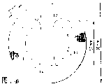
Fig. 1 represents at a slow speed and solid quantitative distribution during fluid injection fast.
When carrier dimensions to be applied not simultaneously.Must correspondingly regulate the pumping capacity and the opening of liquid-filling valve.Find, the fluid injection time of the parts that each 152.4mm is long be 4~5 seconds be favourable.B) reservoir quantity
Can regulate reservoir quantity by the fluid injection time or by measuring liquid level.The latter's method is better, because the suspension of suction same amount in honeycomb to be applied in fact always.Impregnation chamber is design so preferably, the upper surface that makes honeycomb equal height and be immersed in same depth always in this chamber.
Find that if inject the suspension (representing with the fluid injection time) of different amounts, the amount of solid of injecting on the honeycomb of same size changes.This is confirmed by following test 1.Test 1
Six monoblock carriers made from trichroite of criticizing processing together have following size:
144.8×81.3×127mm
62 ducts/cm
2
Wall thickness 0.2mm
These carriers Y-Al
2O
3The suspension coating.Increase the fluid injection time, measure solid and absorb.Coating is carried out under the following conditions:
Y-Al
2O
3Suspension: density 1.568kg/dm
3
Viscosity 40-42 centipoise
22.5 ℃ of temperature
Hold-time: 0.5 second
Find time: 8.0 seconds
Finish extremely from finding time
The equal time between the blowing: 4.0 seconds
The coating cycle is long: 20.0 seconds
Blow pressure 150,140,130 millibars/temperature
Spend 45 ℃
| Vehicle weight g | Blowing back weight g | The wet g that absorbs of BD | Dry weight g | Do and absorb g | Hold-time sec | Solid absorbs % |
| 569 569 541 544 543 543 | 952 954 916 913 882 878 | 383 385 375 369 339 335 | 754 755 721 721 703 701 | 185 186 180 177 160 158 | 6.7 6.7 7.7 7.7 8.7 8.7 | 48.30 48.31 48.00 47.97 47.20 47.16 |
As above shown in the table, when increasing, reservoir quantity (represents) that solid absorbs minimizing with the fluid injection time that prolongs under the given pumping capacity, and the ratio inversion of absorbed solid and absorbed water, the amount of absorbed water is bigger.C) hold-time
Hold-time is the time between fluid injection end and the extraction beginning.During this period of time, be full of coating suspension in the honeycomb, and continue therefrom suction.As a result, the coating of being close to cell walls reaches high solid concentration.
When the receptivity of cellular material descended, the effect of hold-time also descended to some extent, therefore must regulate the duct wall thickness of cellular material.Test 2
Carrier is regulated and 1 identical (the 6.7 seconds filler time) of test with other
| Vehicle weight g | Blowing back weight g | The wet g that absorbs of BD | Dry weight g | BD does and absorbs g | Hold-time sec | Solid absorbs % |
| 550 550 550 550 550 550 | 940 942 955 957 970 967 | 390 392 405 407 420 417 | 735 736 742 743 748 747 | 185 186 192 193 198 197 | 0.5 0.5 1.0 1.0 2.0 2.0 | 47.44 47.45 47.41 47.42 47.14 47.24 |
Prolong the hold-time, become water favourable by solid/water system that cellular material absorbed.But wet absorption and dried the absorption have also correspondingly been improved.D) extract out (speed and time)
When the hold-time finished, the emptying honeycomb also had influence on the amount of the coating that is absorbed by extraction.Evacuation procedure depends on pumping capacity and time.
In next one test, finding time progressively increases, and the emptying in duct as a result improves.As the result of residual absorption ability, coating deposited more effectively is fixed on the cell walls of honeycomb.Test 3
Adjusting and carrier are as testing 1.(the fluid injection time is 6.7 seconds)
| Vehicle weight g | Blowing back weight g | The wet g that absorbs of BD | Dry weight g | BD does and absorbs g | Sec finds time | The solid % that absorbs |
| 573 573 557 558 573 575 | 956 959 937 950 968 990 | 383 386 380 392 395 415 | 753 744 738 744 701 775 | 180 171 181 186 188 200 | 8.0 8.0 9.0 9.0 10.0 10.0 | 47.00 44.30 47.63 47.45 47.60 48.19 |
E) time between extraction and the blowing
Extraction and blowing removing subsequently or the time between the siphon also have influence on solid and absorb.If particularly the step of front is carried out very soon.And the words that the amount of the water that is absorbed does not considerably reach capacity.
Test 4 these effects of check.
Carrier and adjusting as test 1.
(time of charging into is 6.7 seconds)
| Vehicle weight g | Blowing back weight g | The wet g that absorbs of BD | Dry weight g | BD does and absorbs g | Intermittent time sec | The solid % that absorbs |
| 570 572 573 573 574 572 571 570 568 | 953 956 952 963 966 957 968 965 967 | 383 384 379 390 392 385 397 395 399 | 753 756 755 760 762 757 762 760 760 | 183 184 182 187 188 185 191 190 192 | 4.0 4.0 4.0 6.0 6.0 6.0 8.0 8.0 8.0 | 47.78 47.92 48.02 47.92 47.98 48.03 48.10 48.09 48.08 |
After extracting out, the amount that remains in the suspension in the duct is also influential.This influence depends on that (theoretical pump capacity of return pump is 3m to the pumping capacity of finding time and installing in test
2/ n).
The present invention does more detailed the explanation with reference to drawings and Examples.These figure are:
Fig. 1 represents the solid quantitative distribution
A) in the prior art common fluid injection at a slow speed and
B) the quick fluid injection among the present invention;
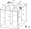
Fig. 2 represents device used among the present invention;
Fig. 3 represents vertical distribution of resulting coating among the embodiment 1;
Fig. 4 represents the radial distribution of resulting coating among the embodiment 2;
Fig. 5 represents the surface arrangement of resulting coating among the embodiment 3;
Fig. 6 represents vertical distribution of resulting coating among the embodiment 4;
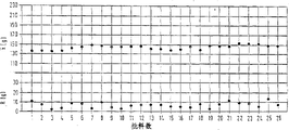
Fig. 7 represents among the embodiment 5 average absorption of the coating that the method with prior art obtains, to quite a large amount of cellular components, and
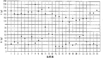
Fig. 8 represents being evenly distributed of the coating that obtains with the inventive method among the embodiment 5, to quite a large amount of cellular components.
Used impregnation chamber has lower array structure in the coating method of this method, such as Fig. 2: a rectangle, vertical impregnation chamber housing 16 is connected with a rectangular substrate 15, and the size of rectangular substrate 15 is slightly larger than the cross section of impregnation chamber housing. A centre bore is arranged on the substrate, wherein be screwed into one with the sleeve 19 of the slip of folding bellows 18 protections, to accept up and down movably piston 3. Injection and vacuum pump line 9 also extend through substrate. On its top, the axis of the piston heads on a plate 2 to support cellular components. Rectangle inner housing 11 has a upper ring edge of inwardly giving prominence to, and it and housing closely cooperate, and has formed " permanent " lower impregnation chamber packing ring. It defines a pre-preg chamber 10.
Interchangeable packing ring 12,13,14 can be placed on the inner housing packing ring 11. They are dish types, the diameter of the bigger dried honeycomb 1 of A/F, and in fact they consisted of cylindrical wall to the honeycomb that moves up and down as a result. The thickness of dish and the number of interchangeable packing ring depend on the length of the honeycomb that will apply. The bottom of given honeycomb and top embed in the impregnation chamber housing 16 with 8,7 supports of the expandable rubber collar, the collar 8,7. Profile and the impregnation chamber of the collar adapt, and shape and carrier adapt in it. Near the interchangeable packing ring 13 ring spring is embedded in below 8, as the support lasso 6 of honeycomb. Annular module 5 above the configuration collar is as the lid 5 of impregnation chamber.
Impregnation chamber housing 16 is folded down from being positioned at 17 scaffold. Folding bellows 18 have been protected being slidingly connected between piston 3 and the sliding sleeve 19, to avoid the infiltration of coating suspension.
Be configured in above the honeycomb and brush block plate 20 for measuring liquid level with the center of dipping chamber cap outside. The bottom position of piston represents that with 22 tip position represents with 21. Possible liquid level in the label 23 expression impregnation chamber.
Order of operation in the impregnation chamber is as follows:
--piston 3 moves to tip position 21;
--carrier 1 is placed on the gripper shoe 2 of piston;
--piston 3 moves to bottom position 22;
--carrier is stayed on the lasso 6;
--top cover ring 7 and the end collar 8 expand;
--under full topping-up pump flow, perhaps open fully under the liquid-filling valve, by pipeline 9 beginnings
Supply suspension;
--the fluid injection time 1 stops;
--continue supply suspension 9, use amount of restriction;--the fluid injection time 2 stops;--when fluid injection during to liquid level 23, brush block the supply that plate 20 has been closed (suspension);--the retention time stops;--the end collar 8 and top cover ring 7 are loose, the drain pump entry into service;--evacuated time 1 stops;--the end collar 8 expands;--evacuated time 2 stops;--the end collar 8 is loose, and top cover ring 7 expands;--drift 3 moves upward, and the honeycomb on the slurcam 21 is by top cover ring (in this process, the coating of adhesion is erased from carrier surface);--piston arrives tip position 21;--top cover ring 7 is loose;--return pump cuts out;--shift out honeycomb and blowing or emptying by siphon.
Embodiment 1
The ceramic monolith spare made from trichroite (Messers Corning Glass) has following size:
Diameter: 101.6mm
Length: 152.4mm
Perforation density: 42 eyelets/cm
2
Wall thickness: 0.31mm
In impregnation chamber, apply with coating with one step.
Coating has following character:
Concentration: 48.7wt% oxide compound
(the composition of oxide compound: 84.92wt%Al
2O
3,
5.30wt%CeO
2,
6.82wt%ZrO
2,
2.96wt%Fe
2O
3)
Viscosity: 50 centipoises
Temperature: 30 ℃
Particle size: the adjusting of φ 4-5 μ m impregnation chamber:
Fluid injection time 1:1.5 second/liquid-filling valve position 100%
/ 4.8 seconds
Fluid injection time 2:3.3 second/charge into valve position 20%
Hold-time: 0.0 second
Evacuated time 1:1.5 second
Evacuated time 2:2.5 second
Discharge: 0.8 second
Cover ring compression 1 top (7): 2.0 crust
Cover ring compression 1 end (8): 4.0 crust
Time before the blowing: 2.5 seconds
Blow pressure: 150 millibars
Blow-time: 13 seconds
Parts after the coating in being heated to 150 ℃ airflow dry 0.5 hour are then 500 ℃ of thermal treatments 1 hour.
After the thermal treatment. this parts coating is with the 150g coating.Vertically distribute as shown in Figure 3.Embodiment 2
Metallic carrier (Messrs Behr) data:
Diameter: 90.0mm
Length: 74.5mm
Perforation density: 62 eyelets/cm
2
Wall thickness: 0.05mm
In impregnation chamber, apply with coating with one step.
Coating has following character:
Concentration: the 56.3wt% oxide compound,
(oxide compound is formed: 77wt%Al
2O
3, 13wt%CeO
2, 7wt%ZrO
2, 3wt%Fe
2O
3) adjusting of impregnation chamber:
Fluid injection time 1:1.8 second
Fluid injection time 2:1.2 second
Hold-time: 0.0 second
Evacuated time 1) 4.0 second
*)
Evacuated time 2)
Discharge: 0.6 second
The cover ring compression, top (7): 4.0 crust
The cover ring compression, the end (8): 4.0 crust
*) with regard to these parts, coating need not to erase from the surface.The control mode of the collar is different with embodiment 1.When the hold-time finished, two collars all closed, and discharged and promptly opened at the beginning.
Time before the blowing: 1.5 seconds
Blow pressure: 100 millibars
Blow-time: 8 seconds
Parts after the coating in the air-flow of 150 ℃ belt moisture eliminator erectly dry 0.5 hour are then 300 ℃ of thermal treatments 0.33 hour.
The coating of measuring after the thermal treatment is absorbed as 82g
Parts have a very slick coating.Only measured the radial coating and distributed, as shown in Figure 4.
Represent coating with the percentage ratio of total fluid-injecting amount:
K1=101.4%
K2=99.6%
K3=99.9%
K4=100.3%
The radial uniform distribution is fine.Embodiment 3
The data of the ceramic monolith parts made from mullite (Messrs NGK):
Length: 150mm
Width: 150mm
Highly: 150mm
Perforation density: 8 eyelets/cm
2
Wall thickness: 0.62mm
In impregnation chamber, apply with coating with one step.
Coating has following character:
Concentration: the 64.2wt% oxide compound,
(87wt% Al
2O
3,6wt% CeO
2,7wt% ZrO
2)
Viscosity>100 centipoises
30 ℃ of temperature
The adjusting of particle size φ 8 μ m impregnation chamber
Fluid injection time 1:4 second
Fluid injection time 2:6 second
Hold-time: 0.5 second
Evacuated time 1:1.5 second
Evacuated time 2:8.0 second
Discharge: 0.7 second
The cover ring compression, top (7): 0.8 crust
The cover ring compression, the end (8): 1.5 crust
Blow-time: 3.0 seconds
Blow pressure: 150 millibars
Blow-time: 14 seconds
Parts after the coating in the air-flow of 180 ℃ belt moisture eliminator erectly dry 1 hour are then 240 ℃ of thermal treatments 0.5 hour.
The coating of measuring after the thermal treatment is absorbed as 402g.
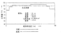
Coating distributes as shown in Figure 5, distributes very evenly in all directions coating.
Surface-area (m in core district 1-4 measurement
2/ g): core 1 core 2 cores 3 core 4a 16 16 16 16 tops the 3rd b 16 17 16 17 middle parts the 3rd c 17 16 17 16 bottoms the 3rd embodiment 4
The data of the ceramic monolith parts made from trichroite (Messrs Conning):
Length: 160.0mm
Width: 169.7mm
Highly: 80.8mm
Perforation density: 62 eyelets/cm
2
Wall thickness: 0.16mm
In impregnation chamber, apply time coating with one step.
Coating has following character:
Concentration: 58.05wt% oxide compound
(oxide compound is formed: 72wt%Al
2O
3, 26wt%CeO
2, 2wt%ZrO
2) adjusting of impregnation chamber
Fluid injection time 1:2.5 second
Fluid injection time 2:3.0 second
Hold-time: 0.0 second
Evacuated time 1:2.0 second
Evacuated time 2:2.0 second
Discharge: 0.6 second
The cover ring compression, top (7): 1.0 crust
The cover ring compression, the end (8): 3.0 crust
Come before the emptying by siphon
Time: 2.5 seconds
Siphon negative pressure: 400 millibars
Siphon time 1:7.0 second
Intermittent time: 3.0 seconds
Siphon time 2:9.5 second
After coming emptying by siphon, parts in the air-flow of 150 ℃ belt moisture eliminator erectly dry 0.5 hour are then 500 ℃ of thermal treatments 1 hour.
Coating through heat treated parts is absorbed as 296g.
Vertical distribution of coating as shown in Figure 6.Embodiment 5
Technology to quite a large amount of ceramic monolith parts of being made by Conning Glass compares:
Diameter: 101.5mm
Length: 152.4mm
Perforation density: 42 eyelets/cm
2
Wall thickness: 0.31mm
Sedimentary oxide coating has following composition:
Al
2O
3 86.0%
CeO
2 6.3%
ZrO
2 5.4%
Fe
2O
3 2.3%
Target is each parts coating 154 ± 23g.
Quantitatively and regulate:
Prior art the inventive method
The number 5 of size 100 every BT(batch testing) spares of number=2 1 batch of materials of Fig. 7 Fig. 8 N=2,600 2600 n=104 104 concentration (Conc.) G%=42.2-43.8 46.76-47.17 viscosity centipoise=38-42 49-55 impregnation steps
Under the quantity and adjusting of prior art, product is characterised in that the wide fluctuations of average absorption, and same dispersed on a large scale between the individual values,
Processing quality=CP value<1.0
In coating method of the present invention, average (absorption) is uniformly, do not have dispersiveness:
Good processing quality=CP value>2.0CP value
Specific performance index CP is the throughput of technology and the relation between the specific visitor difference.
The explanation<1.00 of=standard deviation CP value is insufficient, technology also produces substandard products 1.00-1.33 inevitably and only can accept, it is good to need to improve 1.34-2.00, and proving to improve has lasting effect>2.00 fine, secular target