CN103899886A - Supporting base - Google Patents
Supporting base Download PDFInfo
- Publication number
- CN103899886A CN103899886A CN201210587875.7A CN201210587875A CN103899886A CN 103899886 A CN103899886 A CN 103899886A CN 201210587875 A CN201210587875 A CN 201210587875A CN 103899886 A CN103899886 A CN 103899886A
- Authority
- CN
- China
- Prior art keywords
- resisting part
- electron device
- portable electron
- supporting base
- tuning portion
- Prior art date
- Legal status (The legal status is an assumption and is not a legal conclusion. Google has not performed a legal analysis and makes no representation as to the accuracy of the status listed.)
- Granted
Links
- NJPPVKZQTLUDBO-UHFFFAOYSA-N novaluron Chemical compound C1=C(Cl)C(OC(F)(F)C(OC(F)(F)F)F)=CC=C1NC(=O)NC(=O)C1=C(F)C=CC=C1F NJPPVKZQTLUDBO-UHFFFAOYSA-N 0.000 claims description 31
- 238000000465 moulding Methods 0.000 claims description 2
- 238000004080 punching Methods 0.000 claims description 2
- 230000015572 biosynthetic process Effects 0.000 claims 1
- 241000208340 Araliaceae Species 0.000 description 2
- 235000005035 Panax pseudoginseng ssp. pseudoginseng Nutrition 0.000 description 2
- 235000003140 Panax quinquefolius Nutrition 0.000 description 2
- 238000010586 diagram Methods 0.000 description 2
- 235000008434 ginseng Nutrition 0.000 description 2
- 238000000034 method Methods 0.000 description 1
- 238000005728 strengthening Methods 0.000 description 1
- 230000000007 visual effect Effects 0.000 description 1
Images



Landscapes
- Details Of Audible-Bandwidth Transducers (AREA)
Abstract
A supporting base is used for supporting a portable electronic device. The supporting base comprises a base body and a supporting plate, the supporting plate comprises an abutting-against portion and a tone tuning portion, the abutting-against portion is connected to the top face of the base body, a preset angle is formed between the abutting-against portion and the top face of the base body, the tone tuning portion is connected to the side edge of the abutting-against portion, the tone tuning portion protrudes out of the plane of the abutting-against portion, the abutting-against portion and the top face of the base body are used for bearing the portable electronic device, the tone tuning portion corresponds to a loudspeaker of the portable electronic device, and resonance is carried out on sounds generated by the loudspeaker of the tone tuning portion, and the sounds are guided out.
Description
Technical field
The invention relates to a kind of supporting base of portable electron device, relate in particular to a kind of quality supporting base of strengthening portable electron device bass.
Background technique
In the design of general portable electron device, owing to being subject to the restriction of designing requirement of integral thickness and volume, be generally the designed internal resonance insufficient space of loudspeaker of portable electron device, and cause portable electron device loudspeaker go out sound bad.In addition, these portable electron devices can use an external supporting frame that portable electron device can be stood at an angle conventionally, to replace the hand-held mode of user, conveniently watch the display screen of portable electron device for user.But supporting frame is only for supporting portable electron device, what there is no that design dependency structure can strengthen portable electron device goes out timbre matter, make the function singleness of supporting frame, and portable electron device still exists out the problem that timbre matter is not high.
Summary of the invention
In view of foregoing, be necessary to provide a kind of supporting base that goes out timbre matter that promotes portable electron device.
A kind of supporting base, for supporting a portable electron device.Described supporting base comprises pedestal and dunnage, dunnage comprises resisting part and tuning portion, this resisting part is connected in base top surface, and be a predetermined angle setting with base top surface, tuning portion is connected in the side of resisting part, and tuning portion protrudes from the plane of resisting part, and the end face of this resisting part and pedestal is used for carrying a portable electron device, tuning portion is corresponding with the loudspeaker of portable electron device, and the sound generation resonance that sends for loudspeaker of tuning portion sound is derived.
A kind of supporting base, for supporting a portable electron device.Described supporting base comprises pedestal and dunnage, dunnage comprises resisting part and tuning portion, this resisting part is connected in base top surface, and be a predetermined angle setting with base top surface, and tuning portion is connected in the side of resisting part, and tuning portion protrudes from the plane of resisting part, the end face of this resisting part and pedestal is used for carrying a portable electron device, tuning portion comprises cavity, and cavity is relative with the loudspeaker of portable electron device, or the loudspeaker of accommodating portable electron device in the inner.
Described supporting base supports a portable electron device at an angle by pedestal and dunnage, facilitates user to watch.And by two tuning portions being set in the relative both sides of dunnage, make the sound that portable electron device loudspeaker sends occur to be directed to user after resonance in tuning portion, effectively promoted the quality of sound.Described supporting base has several functions, simple in structure and easy to use.
Brief description of the drawings
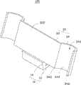
Fig. 1 is the stereogram of the supporting base of preferred embodiment of the present invention.
Fig. 2 is the stereogram at another visual angle of supporting base shown in Fig. 1.
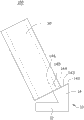
Fig. 3 is the side view of supporting base shown in Fig. 1.
Fig. 4 is the schematic diagram that shown in Fig. 1, supporting base carries a portable electron device.
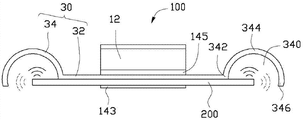
Plan view when Fig. 5 is the carrying of supporting base shown in Fig. 4 portable electron device.
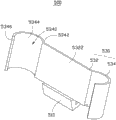
Fig. 6 is the stereogram of the supporting base of second embodiment of the invention.
Fig. 7 is the schematic diagram that shown in Fig. 6, supporting base carries a portable electron device.
Plan view when Fig. 8 is the carrying of supporting base shown in Fig. 7 portable electron device.
Primary component symbol description
| |
100、500 |
| |
10、510 |
| |
12 |
| |
14 |
| |
142 |
| |
144 |
| The |
146 |
| The first inclined- |
143 |
| The second inclined- |
145 |
| |
30、530 |
| Resisting |
32、532 |
| |
322、5322 |
| |
34、534 |
| |
340、5340 |
| Connecting |
342、5342 |
| |
344、5344 |
| |
346、5346 |
| |
200 |
| |
210 |
Following embodiment further illustrates the present invention in connection with above-mentioned accompanying drawing.
Embodiment
Refer to Fig. 1, the supporting base 100 of a preferred embodiment of the present invention is for supporting portable electron device.Described portable electron device can be mobile phone, panel computer, PDA Personal Digital Assistant (Personal Digital Assistant, PDA) and e-book etc.
Refer to Fig. 1 and Fig. 2, described supporting base 100 comprises pedestal 10 and dunnage 30, and dunnage 30 is erected on pedestal 10, and is a predetermined angle setting with pedestal 10.In the present embodiment, this dunnage 30 and pedestal 10 integrated punching moulding.
See also Fig. 3, described pedestal 10 is roughly L-shaped.Pedestal 10 comprises plat part 12 and joint 14.It is tabular that plat part 12 is level, for being positioned over a table top.Joint 14 is roughly inverted trapezoidal, and its bottom is connected in one end of plat part 12, and is upwards extended to form by bottom.The end face of joint 14 is roughly V-shaped along fore-and-aft direction, comprises the first end 142, trench 144 and the second end 146 that set gradually along fore-and-aft direction.The end face medial recess of joint 14 forms described trench 144, and is extended and form respectively two the first inclined-plane 143 and the second inclined-planes 145 that arrange at an angle to first end 142 and the second end 146 respectively by this trench 144.Wherein, the first inclined-plane 143 is an obtuse angle setting with the angle of horizontal plane.
Described dunnage 30 comprises resisting part 32 and two tuning portions 34.This resisting part 32 is planar, and its underpart is connected on the trench 144 of pedestal 10, and is a predetermined angle setting with this first inclined-plane 143.This resisting part 32 is supporting surface 322 towards the one side on the first inclined-plane 143, and this supporting surface 322 is an obtuse angle setting with horizontal angle.Thereby the supporting surface 322 of this resisting part 32 forms a supporting bable tops with the first inclined-plane 143 of pedestal 10.The length of this resisting part 32 is long compared with the lateral length of pedestal 10, and the opposite end of resisting part 32 extends respectively the both sides of this pedestal 10.
Described two tuning portions 34 are arranged at respectively the opposite end of this resisting part 32.Each tuning portion 34 comprises cavity 340 and jointly surrounds the connecting end 342 of described cavity 340, wall extension 344 and free end 346.Connecting end 342 is connected in the side margin of resisting part 32.It is tabular that wall extension 344 is circular arc, and it is from connecting end 342 to extending with the opposing direction of this supporting surface 322, and wall extension 344 protrudes from the plane (ginseng Fig. 4) at resisting part 32 places towards the direction that deviates from supporting surface 322.Free end 346 is connected in the side of wall extension 344 away from connecting end 342.Free end 346 protrudes from the plane (ginseng Fig. 4) at supporting surface 322 places.Between this connecting end 342 and free end 346, form the opening relative with wall extension 344.
Refer to Fig. 4, when described supporting base 100 supports a portable electron device 200, a side of portable electron device 200 is carried on the first inclined-plane 143 of pedestal 10, and the back side is carried on the supporting surface 322 of dunnage 30.The front of this portable electron device 200 is provided with display screen 210.In the time that portable electron device 200 is carried on the first inclined-plane 143 and supporting surface 322, because the first inclined-plane 143 is an obtuse angle setting with horizontal plane, supporting surface 322 is relative with the first inclined-plane 143 and be an obtuse angle setting with horizontal plane, so portable electron device 200 can firmly be carried on the first inclined-plane 143 and supporting surface 322.Portable electron device 200 supports described supporting surface 322, portable electron device 200 is an obtuse angle placement with horizontal plane, be that display screen 210 is the angle of looking up, can conveniently watch for user, make the angle of inclination of display screen 210 meet human body and watch more comfortable angle.
See also Fig. 4 and Fig. 5, the loudspeaker (not shown) of portable electron device 200 is arranged at respectively the two ends that portable electron device 200 is relative.The sound mode that goes out of loudspeaker can be for to sound from relative two ends, the back side of portable electron device 200 or to sound from two relative side.Each cavity 340 of described supporting base 100 is relative with portable electron device 200 one of them loudspeaker.In the time that loudspeaker is sounded from relative two ends, the back side of portable electron device 200, sound is the middle part to this wall extension 344 just, sound is at the interior generation resonance of cavity 340 of this tuning portion 34, and under the leading role of the opening of tuning portion 34, sound is conducted to the direction of opposing this wall extension 344, listens to for user.
In the time that loudspeaker is sounded from two relative sides of portable electron device 200, sound is the side near free end 346 to wall extension 344 just, between this tuning portion 34, there is resonance in sound, and under the leading role of the opening of tuning portion 34, sound is conducted to the direction of opposing this wall extension 344, listens to for user.Thus, this tuning portion 34 forms the sound chamber of portable electron device 200, for space and the sound leading role of the sound generation resonance that portable electron device 200 sends are provided, has effectively promoted the quality of sound, and sound is conducted to user better.
Refer to Fig. 6, the supporting base 500 of second embodiment of the invention comprises pedestal 510 and dunnage 530.Dunnage 530 comprises resisting part 532 and two tuning portions 534.Resisting part 532 comprises supporting surface 5322.The structure of the pedestal 510 in the second embodiment is identical with the structure of the pedestal 10 in the first embodiment.In the second embodiment, to be arranged at the mode of pedestal 510 identical with the mode that resisting part 32 in the first embodiment is arranged at pedestal 10 for resisting part 532.In the second embodiment, connecting end 5342, wall extension 5344 and free end 5346 that each tuning portion 534 comprises cavity 5340 and jointly surrounds described cavity 5340 and connect successively.Connecting end 5342 is connected in the side margin of resisting part 532.It is tabular that wall extension 5344 is circular arc, its direction from connecting end 342 to these supporting surface 5322 back sides is extended, and wall extension 5344 protrudes from the plane at resisting part 532 places towards the direction that deviates from supporting surface 5322 near the part of connecting end 5342, the middle part of wall extension 5344 and the part near free end 5346 protrude from the plane at resisting part 532 places towards the direction of supporting surface 5322.
See also Fig. 7 and Fig. 8, supporting base 500 carries a portable electron device 200 in pedestal 510 and dunnage 530.One of them loudspeaker that each cavity 5340 of described supporting base 500 is accommodated portable electron device 200 in the inner.In the time being arranged at the loudspeaker (not shown) at relative two ends, portable electron device 200 back sides and sounding, sound is the side near connecting end 5342 to wall extension 5344 just; In the time being arranged at 200 two relative sides of portable electron device and sounding, sound is the middle part to wall extension 5344 just.Sound is at the interior generation resonance of cavity 5340 of this tuning portion 534, and under the leading role of the opening of tuning portion 534, sound is conducted to the direction of opposing this wall extension 5344, listens to for user.
Described supporting base 100 supports a portable electron device 200 at an angle by pedestal 10 and dunnage 30, facilitates user to watch.And by two tuning portions 34 being set in the relative both sides of dunnage 30, the sound that portable electron device 200 loudspeakers are sent is directed to user after resonance occurs in tuning portion 34, has effectively promoted the quality of sound.Described supporting base 100 has several functions, simple in structure and easy to use.
Claims (10)
1. a supporting base, be used for supporting a portable electron device, it is characterized in that: described supporting base comprises pedestal and dunnage, dunnage comprises resisting part and tuning portion, this resisting part is connected in base top surface, and be a predetermined angle setting with base top surface, tuning portion is connected in the side of resisting part, tuning portion protrudes from the plane of resisting part, the end face of this resisting part and pedestal is used for carrying a portable electron device, tuning portion is corresponding with the loudspeaker of portable electron device, and the sound generation resonance that sends for loudspeaker of tuning portion sound is derived.
2. supporting base as claimed in claim 1, it is characterized in that: the quantity of described tuning portion is two, be connected to the two ends that described resisting part is relative, two tuning portions are corresponding with the loudspeaker that is arranged at portable electron device opposite end, and the sound generation resonance that each tuning portion sends for corresponding loudspeaker is also derived sound.
3. supporting base as claimed in claim 1, is characterized in that: described pedestal and dunnage are by integrated punching moulding, and described pedestal comprises plat part and joint, the L-shaped setting of this joint and plat part, and this plat part is used for being positioned over a table top.
4. supporting base as claimed in claim 3, it is characterized in that: the bottom of described joint is connected in one end of this plat part, the end face of joint is V-shaped along fore-and-aft direction, comprise the first end, trench and the second end that set gradually along fore-and-aft direction, this trench is caved inward and is formed by end face middle part, trench extends to first end and the second end the first inclined-plane and the second inclined-plane that formation is respectively a predetermined angle setting respectively, and the first inclined-plane is horizontal by an obtuse angle setting.
5. supporting base as claimed in claim 4, is characterized in that: it is tabular that described tuning portion is circular arc, and described resisting part is planar, and resisting part is horizontally set on this trench, and the both sides of extending respectively pedestal, the relative two ends of resisting part.
6. supporting base as claimed in claim 5, is characterized in that: described resisting part is supporting surface towards the one side on this first inclined-plane, and this supporting surface is horizontal by a predetermined angle setting, and this supporting surface and the first inclined-plane be the described portable electron device of carrying jointly.
7. supporting base as claimed in claim 6, is characterized in that: described tuning portion comprises cavity and the connecting end, wall extension and the free end that connect successively, and connecting end, wall extension and free end surround described cavity jointly; This connecting end is connected in the side margin of resisting part, and the relative both sides of wall extension connect respectively this connecting end and free end, and free end is arranged at the side of wall extension away from resisting part, forms the opening relative with wall extension between connecting end and free end.
8. supporting base as claimed in claim 7, is characterized in that: described wall extension protrudes from the plane at resisting part place towards the direction at the back side of supporting surface.
9. supporting base as claimed in claim 7, it is characterized in that: described wall extension is to the plane that protrudes from resisting part place near the part of connecting end towards the direction at the back side of supporting surface, and the middle part of wall extension and close free-ended part protrude from the plane at resisting part place towards the direction of supporting surface.
10. a supporting base, be used for supporting a portable electron device, it is characterized in that: described supporting base comprises pedestal and dunnage, dunnage comprises resisting part and tuning portion, this resisting part is connected in base top surface, and be a predetermined angle setting with base top surface, tuning portion is connected in the side of resisting part, tuning portion protrudes from the plane of resisting part, the end face of this resisting part and pedestal is used for carrying a portable electron device, tuning portion comprises cavity, and cavity is relative with the loudspeaker of portable electron device, or the loudspeaker of accommodating portable electron device in the inner.
Priority Applications (1)
| Application Number | Priority Date | Filing Date | Title |
|---|---|---|---|
| CN201210587875.7A CN103899886B (en) | 2012-12-29 | 2012-12-29 | Supporting base |
Applications Claiming Priority (1)
| Application Number | Priority Date | Filing Date | Title |
|---|---|---|---|
| CN201210587875.7A CN103899886B (en) | 2012-12-29 | 2012-12-29 | Supporting base |
Publications (2)
| Publication Number | Publication Date |
|---|---|
| CN103899886A true CN103899886A (en) | 2014-07-02 |
| CN103899886B CN103899886B (en) | 2017-05-24 |
Family
ID=50991385
Family Applications (1)
| Application Number | Title | Priority Date | Filing Date |
|---|---|---|---|
| CN201210587875.7A Expired - Fee Related CN103899886B (en) | 2012-12-29 | 2012-12-29 | Supporting base |
Country Status (1)
| Country | Link |
|---|---|
| CN (1) | CN103899886B (en) |
Cited By (1)
| Publication number | Priority date | Publication date | Assignee | Title |
|---|---|---|---|---|
| CN109751487A (en) * | 2017-11-07 | 2019-05-14 | 丹阳市日晟工业设备有限公司 | A kind of waveform plate stamping parts |
Citations (5)
| Publication number | Priority date | Publication date | Assignee | Title |
|---|---|---|---|---|
| JP2005136895A (en) * | 2003-10-31 | 2005-05-26 | Sony Ericsson Mobilecommunications Japan Inc | Desktop holder and viewing/listening system |
| CN2779773Y (en) * | 2005-06-08 | 2006-05-10 | 张恺龙 | Sound Optimized Amplifier |
| CN201009822Y (en) * | 2007-01-26 | 2008-01-23 | 佛山市顺德区顺达电脑厂有限公司 | Public address support |
| CN101377961A (en) * | 2007-08-28 | 2009-03-04 | 华硕电脑股份有限公司 | Fixing frame for handheld electronic device vehicle |
| CN202171103U (en) * | 2011-05-31 | 2012-03-21 | 讯凯国际股份有限公司 | Improved structure of support frame of portable electronic device |
-
2012
- 2012-12-29 CN CN201210587875.7A patent/CN103899886B/en not_active Expired - Fee Related
Patent Citations (5)
| Publication number | Priority date | Publication date | Assignee | Title |
|---|---|---|---|---|
| JP2005136895A (en) * | 2003-10-31 | 2005-05-26 | Sony Ericsson Mobilecommunications Japan Inc | Desktop holder and viewing/listening system |
| CN2779773Y (en) * | 2005-06-08 | 2006-05-10 | 张恺龙 | Sound Optimized Amplifier |
| CN201009822Y (en) * | 2007-01-26 | 2008-01-23 | 佛山市顺德区顺达电脑厂有限公司 | Public address support |
| CN101377961A (en) * | 2007-08-28 | 2009-03-04 | 华硕电脑股份有限公司 | Fixing frame for handheld electronic device vehicle |
| CN202171103U (en) * | 2011-05-31 | 2012-03-21 | 讯凯国际股份有限公司 | Improved structure of support frame of portable electronic device |
Cited By (1)
| Publication number | Priority date | Publication date | Assignee | Title |
|---|---|---|---|---|
| CN109751487A (en) * | 2017-11-07 | 2019-05-14 | 丹阳市日晟工业设备有限公司 | A kind of waveform plate stamping parts |
Also Published As
| Publication number | Publication date |
|---|---|
| CN103899886B (en) | 2017-05-24 |
Similar Documents
| Publication | Publication Date | Title |
|---|---|---|
| CN204795204U (en) | Mobile terminal's speaker structure | |
| CN101141499B (en) | A mobile phone with a two-in-one speaker sinking structure | |
| US9062812B2 (en) | Holder for portable electronic device | |
| TWI539832B (en) | Portable electronic device | |
| US11211690B2 (en) | Middle frame assembly and electronic device | |
| CN102333263B (en) | Electronic device | |
| CN201766626U (en) | Mobile terminal | |
| CN101588002B (en) | Phone jack component | |
| CN202043261U (en) | an electronic product | |
| TW200533219A (en) | Speaker module frame, speaker module therewith, and electrical device with the speaker module | |
| CN202634636U (en) | Horn assembly and electronic equipment | |
| EP3244631B1 (en) | Speaker device with enhancement of bass and electronic device therewith | |
| CN104238657B (en) | Portable electronic device | |
| CN104065773B (en) | Ultra-thin mobile phone | |
| CN103139680B (en) | Electronic equipment | |
| CN104793695A (en) | Hand-held electronic device | |
| CN100444297C (en) | key device | |
| CN203243472U (en) | Mobile terminal and loudspeaker sound cavity for same | |
| CN212305405U (en) | Terminal Equipment | |
| CN102802097A (en) | Sound box structure of electronic device | |
| CN103899886B (en) | Supporting base | |
| TW200713991A (en) | Clam type mobile phone | |
| US20150110308A1 (en) | Handheld electronic device | |
| CN203181198U (en) | Side-sounding sound cavity structure | |
| KR100510355B1 (en) | Folder-type mobile phone with piezo speaker |
Legal Events
| Date | Code | Title | Description |
|---|---|---|---|
| C06 | Publication | ||
| PB01 | Publication | ||
| C10 | Entry into substantive examination | ||
| SE01 | Entry into force of request for substantive examination | ||
| GR01 | Patent grant | ||
| GR01 | Patent grant | ||
| CF01 | Termination of patent right due to non-payment of annual fee |
Granted publication date: 20170524 Termination date: 20201229 |
|
| CF01 | Termination of patent right due to non-payment of annual fee |