CN103867513A - Magnetic rodless cylinder - Google Patents
Magnetic rodless cylinder Download PDFInfo
- Publication number
- CN103867513A CN103867513A CN201210526926.5A CN201210526926A CN103867513A CN 103867513 A CN103867513 A CN 103867513A CN 201210526926 A CN201210526926 A CN 201210526926A CN 103867513 A CN103867513 A CN 103867513A
- Authority
- CN
- China
- Prior art keywords
- magnetic
- piston
- cylinder barrel
- gland
- ring
- Prior art date
- Legal status (The legal status is an assumption and is not a legal conclusion. Google has not performed a legal analysis and makes no representation as to the accuracy of the status listed.)
- Pending
Links
- 210000004907 gland Anatomy 0.000 claims abstract description 12
Images
Landscapes
- Sealing Using Fluids, Sealing Without Contact, And Removal Of Oil (AREA)
Abstract
The invention discloses a magnetic rodless cylinder. The rodless cylinder comprises a sleeve, an outer magnetic ring, an outer magnetic guide plate, an inner magnetic ring, an inner magnetic guide plate, a gland, a piston, a piston shaft, a buffer plunger, a cylinder barrel and an end cover, wherein the sleeve is arranged on the gland, the outer magnetic ring and the inner magnetic ring are respectively arranged between the outer magnetic guide plate and the inner magnetic guide plate, the piston is arranged in the cylinder barrel, the buffer plunger is arranged on the piston shaft and the cylinder barrel is connected with the end cover. The magnetic rodless cylinder provided by the invention is simple in structure, and space can be greatly saved.
Description
Technical field
The present invention relates to a kind of magnetic no-rod cylinder.
Background technique
In prior art, Rodless cylinder refers to and utilizes the direct or indirect mode of piston to connect extraneous actuator, and makes it follow piston to realize reciprocating cylinder, but common Rodless cylinder complex structure, take up room larger.
Summary of the invention
The object of this invention is to provide a kind of magnetic no-rod cylinder.
The technological scheme that the present invention adopted is for achieving the above object: a kind of magnetic no-rod cylinder, comprise sleeve, outer magnetic ring, outer magnetic conductance plate, internal magnetic ring, interior magnetic conductance plate, gland, piston, piston shaft, buffer plunger, cylinder barrel and end cap, described sleeve is arranged on gland, described outer magnetic ring and internal magnetic ring are arranged on respectively between outer magnetic conductance plate and interior magnetic conductance plate, described piston is arranged in cylinder barrel, described buffer plunger is arranged on piston shaft, and cylinder barrel is connected with end cap.
Described end cap is provided with suction port and relief opening.
Between described gland and cylinder barrel, be provided with snap ring.
A kind of magnetic no-rod cylinder of the present invention, simple in structure, can save greatly space.
Brief description of the drawings
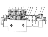
Fig. 1 is the structural representation of a kind of magnetic no-rod cylinder of the present invention.
In figure: 1, sleeve; 2, outer magnetic ring; 3, outer magnetic conductance plate; 4, internal magnetic ring; 5, interior magnetic conductance plate; 6, gland; 7, snap ring; 8, piston; 9, piston shaft; 10, buffer plunger; 11, cylinder barrel; 12, end cap; 13, gas port enters, hesitates.
Embodiment
As shown in Figure 1, magnetic no-rod cylinder, comprise sleeve 1, outer magnetic ring 2, outer magnetic conductance plate 3, internal magnetic ring 4, interior magnetic conductance plate 5, gland 6, piston 8, piston shaft 9, buffer plunger 10, cylinder barrel 11 and end cap 12, described sleeve 1 is arranged on gland 6, described outer magnetic ring 2 and internal magnetic ring 4 are arranged on respectively between outer magnetic conductance plate 3 and interior magnetic conductance plate 5, described piston 8 is arranged in cylinder barrel 11, described buffer plunger 10 is arranged on piston shaft 9, cylinder barrel 11 is connected with end cap 12, end cap 12 be provided with into, relief opening 13, between gland and cylinder barrel, be provided with snap ring 7, a kind of magnetic no-rod cylinder of the present invention, simple in structure, can save greatly space.
Claims (3)
1. a magnetic no-rod cylinder, it is characterized in that: comprise sleeve, outer magnetic ring, outer magnetic conductance plate, internal magnetic ring, interior magnetic conductance plate, gland, piston, piston shaft, buffer plunger, cylinder barrel and end cap, described sleeve is arranged on gland, described outer magnetic ring and internal magnetic ring are arranged on respectively between outer magnetic conductance plate and interior magnetic conductance plate, described piston is arranged in cylinder barrel, described buffer plunger is arranged on piston shaft, and cylinder barrel is connected with end cap.
2. a kind of magnetic no-rod cylinder according to claim 1, is characterized in that: described end cap is provided with suction port and relief opening.
3. a kind of magnetic no-rod cylinder according to claim 1, is characterized in that: between described gland and cylinder barrel, be provided with snap ring.
Priority Applications (1)
| Application Number | Priority Date | Filing Date | Title |
|---|---|---|---|
| CN201210526926.5A CN103867513A (en) | 2012-12-10 | 2012-12-10 | Magnetic rodless cylinder |
Applications Claiming Priority (1)
| Application Number | Priority Date | Filing Date | Title |
|---|---|---|---|
| CN201210526926.5A CN103867513A (en) | 2012-12-10 | 2012-12-10 | Magnetic rodless cylinder |
Publications (1)
| Publication Number | Publication Date |
|---|---|
| CN103867513A true CN103867513A (en) | 2014-06-18 |
Family
ID=50906407
Family Applications (1)
| Application Number | Title | Priority Date | Filing Date |
|---|---|---|---|
| CN201210526926.5A Pending CN103867513A (en) | 2012-12-10 | 2012-12-10 | Magnetic rodless cylinder |
Country Status (1)
| Country | Link |
|---|---|
| CN (1) | CN103867513A (en) |
Cited By (2)
| Publication number | Priority date | Publication date | Assignee | Title |
|---|---|---|---|---|
| CN104819182A (en) * | 2015-04-02 | 2015-08-05 | 青岛理工大学 | Rodless cylinder capable of achieving accurate positioning |
| CN111396401A (en) * | 2020-04-17 | 2020-07-10 | 安徽捷迅光电技术有限公司 | Cylinder load demagnetization detector and detection method thereof |
-
2012
- 2012-12-10 CN CN201210526926.5A patent/CN103867513A/en active Pending
Cited By (2)
| Publication number | Priority date | Publication date | Assignee | Title |
|---|---|---|---|---|
| CN104819182A (en) * | 2015-04-02 | 2015-08-05 | 青岛理工大学 | Rodless cylinder capable of achieving accurate positioning |
| CN111396401A (en) * | 2020-04-17 | 2020-07-10 | 安徽捷迅光电技术有限公司 | Cylinder load demagnetization detector and detection method thereof |
Similar Documents
| Publication | Publication Date | Title |
|---|---|---|
| WO2015102770A3 (en) | Magnetorheological fluid locking system | |
| TR201818555T4 (en) | Spool shuttle crosover valve in split cycle motor. | |
| MX360080B (en) | Reciprocating compressor, pressure packing, and method. | |
| EP2749735A3 (en) | Compressor | |
| WO2013108034A3 (en) | A linear electrical machine | |
| CN203404155U (en) | Disc spring hydraulic cylinder | |
| CN103871776A (en) | Magnetic switch cylinder | |
| CN203627395U (en) | Rodless cylinder | |
| CN204114294U (en) | Remote control Quick-closing check valve | |
| CN106015155A (en) | Compact type multi-position multiple-force cylinder | |
| MX2015012734A (en) | Compression system and method having co-axial flow device. | |
| CN203495644U (en) | Ball high-speed machinery main shaft oil cylinder assembly | |
| CN203584785U (en) | Single plunger ring structure for hydraulic plunger pump | |
| CN104089073A (en) | Remote control fast closing type stop valve | |
| CN202418090U (en) | Plunger-type oil cylinder | |
| CN202811628U (en) | Oil cylinder of gripping apparatus | |
| CN103867517A (en) | Film air cylinder | |
| CN202451507U (en) | Guide sleeve for hydraulic cylinder | |
| CN204099335U (en) | A kind of mechanical type three hydraulic jacks | |
| CN202520696U (en) | Thin cylinder | |
| CN203322263U (en) | Sealing device for guiding sleeve | |
| CN202451510U (en) | Piston rod of hydraulic cylinder | |
| CN103573900A (en) | Pneumatic spring | |
| CN201666284U (en) | Super-thin air cylinder | |
| CN102852886A (en) | Gripper cylinder |
Legal Events
| Date | Code | Title | Description |
|---|---|---|---|
| C06 | Publication | ||
| PB01 | Publication | ||
| C02 | Deemed withdrawal of patent application after publication (patent law 2001) | ||
| WD01 | Invention patent application deemed withdrawn after publication |
Application publication date: 20140618 |