CN103855583A - Stuck-point striking machine for square pin terminals - Google Patents
Stuck-point striking machine for square pin terminals Download PDFInfo
- Publication number
- CN103855583A CN103855583A CN201410124834.3A CN201410124834A CN103855583A CN 103855583 A CN103855583 A CN 103855583A CN 201410124834 A CN201410124834 A CN 201410124834A CN 103855583 A CN103855583 A CN 103855583A
- Authority
- CN
- China
- Prior art keywords
- pin
- pillar
- cylinder
- driving
- needle
- Prior art date
- Legal status (The legal status is an assumption and is not a legal conclusion. Google has not performed a legal analysis and makes no representation as to the accuracy of the status listed.)
- Granted
Links
Images


Landscapes
- Preliminary Treatment Of Fibers (AREA)
- Labeling Devices (AREA)
Abstract
本发明涉及连接器自动化设备技术领域,尤其涉及一种四方针端子打卡点机,一种四方针端子打卡点机,包括机台,所述机台上端按照工序流程依次设置有料带放料轮组、PIN针上料装置、PIN针夹取装置、驱动PIN针夹取装置位移的传动机构、PIN针固定装置、推料装置及料带收料轮组,本发明减少了人工成本,降低生产成本,提高生产效率,并使PIN针与料带的连接更加紧密、牢固,延长连接器的使用寿命,降低连接器的报废率。
The present invention relates to the technical field of connector automation equipment, in particular to a four-direction terminal punching point machine, a four-point terminal punching point machine, including a machine table, and the upper end of the machine table is sequentially provided with a tape discharge wheel group according to the process flow , PIN needle feeding device, PIN needle clamping device, transmission mechanism for driving the displacement of the PIN needle clamping device, PIN needle fixing device, material pushing device and material belt receiving wheel group, the present invention reduces labor cost and production cost , improve production efficiency, and make the connection between the PIN needle and the material tape more tightly and firmly, prolong the service life of the connector, and reduce the scrap rate of the connector.
Description
技术领域 technical field
本发明涉及连接器自动化设备技术领域,尤其涉及一种四方针端子打卡点机。 The invention relates to the technical field of connector automation equipment, in particular to a four-pin terminal punching point machine.
背景技术 Background technique
在现在社会,电子连接器的需求越来越大,连接器内的PIN针需要固定于料带上,传统的方法是通过人工将PIN针卡入料带的卡槽内,由于PIN针尺寸相对较小,所以加工效率不高,而且人工操作,在产品质量方面不容易保证,对于批量生产的话,人工投入较大,生产成本较高,而且,直接将PIN针卡入料带的卡槽内,时间久后,PIN针容易松动、掉落,造成连接器接触不良,减少连接器使用寿命,增加了连接器的报废率。 In today's society, the demand for electronic connectors is increasing, and the PIN pins in the connectors need to be fixed on the tape. The traditional method is to manually insert the PIN pins into the slots of the tape. Smaller, so the processing efficiency is not high, and manual operation is not easy to guarantee product quality. For mass production, the labor input is large and the production cost is high. Moreover, the PIN pin is directly inserted into the card slot of the material tape , After a long time, the PIN pin is easy to loosen and fall off, resulting in poor contact of the connector, reducing the service life of the connector, and increasing the scrap rate of the connector.
发明内容 Contents of the invention
本发明的目的在于针对现有技术的不足提供一种四方针端子打卡点机,本发明减少了人工成本,降低生产成本,提高生产效率,并使PIN针与料带的连接更加紧密、牢固,延长连接器的使用寿命,降低连接器的报废率。 The purpose of the present invention is to provide a four-pin terminal punching point machine for the deficiencies of the prior art. The present invention reduces labor costs, reduces production costs, improves production efficiency, and makes the connection between the PIN needle and the material tape more compact and firm. Extend the service life of the connector and reduce the scrap rate of the connector.
为实现上述目的,本发明的一种四方针端子打卡点机,包括机台,所述机台上端按照工序流程依次设置有料带放料轮组、PIN针上料装置、PIN针夹取装置、驱动PIN针夹取装置位移的传动机构、PIN针固定装置、推料装置及料带收料轮组。 In order to achieve the above-mentioned purpose, a four-direction terminal punching point machine of the present invention includes a machine table, and the upper end of the machine table is sequentially provided with a material belt discharging wheel group, a PIN needle feeding device, a PIN needle clamping device, The transmission mechanism that drives the displacement of the PIN needle clamping device, the PIN needle fixing device, the material pushing device and the material belt receiving wheel group.
作为优选,所述PIN针上料装置包括振动盘和PIN针上料通道,所述PIN针上料通道的进料口与振动盘的出料口连接,所述PIN针上料通道的出料口与PIN针夹取装置连接。 As preferably, the PIN needle feeding device includes a vibrating plate and a PIN needle feeding channel, the feed port of the PIN needle feeding channel is connected with the discharge port of the vibrating plate, and the discharge of the PIN needle feeding channel The mouth is connected with the PIN needle clamping device.
作为优选,所述PIN针夹取装置包括第一支柱,所述第一支柱的中部设置夹座,所述夹座内设置有针板,所述第一支柱的上部设置有打卡点机构,所述第一支柱的底部设置有错料机构,所述针板设置有容置PIN针的第一容置槽,所述错料机构包括推板及驱动推板上下移动的驱动机构,所述推板的顶端与针板的底端抵接,所述驱动机构包括设置于第一支柱底部的基座,所述基座设置有第一驱动气缸及第一支撑板,所述第一驱动气缸与推板之间设置第一连杆,所述第一连杆的一端与推板的底端铰接,第一驱动气缸的活塞杆穿过基座的底板与第一连杆的另一端铰接,所述第一支撑板的底端与第一连杆的中部铰接,所述第一支柱的底板设置有第二驱动气缸和第三驱动气缸,所述第二驱动气缸和第三驱动气缸与基座的底板连接。 Preferably, the PIN needle clamping device includes a first pillar, a clamping seat is provided in the middle of the first pillar, a needle plate is arranged in the clamping seat, and a punching point mechanism is provided on the upper part of the first pillar, so The bottom of the first pillar is provided with a material wrong mechanism, and the needle plate is provided with a first accommodating groove for accommodating PIN needles. The material wrong mechanism includes a push plate and a driving mechanism for driving the push plate to move up and down. The top of the plate abuts against the bottom end of the needle plate, and the driving mechanism includes a base arranged at the bottom of the first pillar, and the base is provided with a first driving cylinder and a first support plate, and the first driving cylinder and A first connecting rod is arranged between the push plates, one end of the first connecting rod is hinged with the bottom end of the push plate, and the piston rod of the first driving cylinder passes through the bottom plate of the base and is hinged with the other end of the first connecting rod, so The bottom end of the first support plate is hinged with the middle part of the first connecting rod, the bottom plate of the first pillar is provided with a second driving cylinder and a third driving cylinder, and the second driving cylinder and the third driving cylinder are connected to the base baseplate connection.
作为优选,所述基座的底板与第一支柱之间设置有第一弹簧。 Preferably, a first spring is arranged between the bottom plate of the base and the first support.
作为优选,所述打卡点机构包括第一压料板、设置于第一支柱上部的第四驱动气缸及第二支撑板,所述第一压料板的底端与针板的顶端抵接,所述第一压料板与第四驱动气缸之间设置有第二连杆,所述第二连杆的一端与第一压料板的顶端铰接,所述第二连杆的另一端与第四驱动气缸的活塞杆铰接,所述第二支撑板的顶端与第二连杆的中部铰接,所述第一压料板与针板的抵接部设置有用于打卡点的刀口。 Preferably, the punching point mechanism includes a first clamping plate, a fourth driving cylinder and a second support plate arranged on the upper part of the first pillar, the bottom end of the first clamping plate abuts against the top end of the needle plate, A second connecting rod is arranged between the first pressing plate and the fourth driving cylinder, one end of the second connecting rod is hinged to the top end of the first pressing plate, and the other end of the second connecting rod is connected to the first pressing plate. The piston rods of the four drive cylinders are hinged, the top of the second support plate is hinged with the middle of the second connecting rod, and the abutting portion of the first holding plate and the needle plate is provided with a knife edge for punching points.
作为优选,所述PIN针夹取装置还包括调整机构,所述调整机构包括设置于夹座侧端的第五驱动气缸,所述第五驱动气缸的活塞杆连接有第一驱动块,所述第一驱动块开设有第一斜面,所述夹座的底端设置有第一驱动轮,所述第一驱动轮与第一驱动块抵接。 Preferably, the PIN pin clamping device further includes an adjustment mechanism, the adjustment mechanism includes a fifth drive cylinder arranged at the side end of the holder, the piston rod of the fifth drive cylinder is connected with a first drive block, and the first drive block is connected to the piston rod of the fifth drive cylinder. A driving block is provided with a first slope, and a first driving wheel is provided at the bottom end of the holder, and the first driving wheel abuts against the first driving block.
作为优选,所述PIN针固定装置包括PIN针推料机构及PIN针固定机构,所述PIN针推料机构和PIN针固定机构之间设置有容下PIN针夹取装置的间隔,所述PIN针推料机构包括第二支柱,所述第二支柱设置有驱动夹座移动第六驱动气缸,所述夹座的上端设置有调整顶针。 As preferably, the PIN needle fixing device includes a PIN needle pushing mechanism and a PIN needle fixing mechanism, and a space for accommodating the PIN needle clamping device is arranged between the PIN needle pushing mechanism and the PIN needle fixing mechanism. The needle pushing mechanism includes a second pillar, and the second pillar is provided with a sixth driving cylinder for driving the clip seat to move, and an adjusting thimble is provided at the upper end of the clip seat.
作为优选,所述PIN针固定机构包括第三支柱,所述第三支柱的顶端设置有第一模座,所述第一模座的上端开设第一料槽,所述第一模座的中部设置有第二容置槽,所述第二容置槽内设置有针排,所述针排与第二容置槽的之间设置有第二弹簧,所述针排的中部开设有卡接槽,所述第三支柱还设置有锁死机构,所述锁死机构包括卡接块及驱动卡接块伸入卡接槽内的第七驱动气缸,所述卡接槽开设有第二斜面,所述卡接块开设有第三斜面,所述第二斜面与第三斜面滑动配合;所述针排的上端设置有第二压料板,所述第二压料板的底端与针排抵接,所述针排的上方还设置有第八驱动气缸,所述第八驱动气缸的活塞杆连接有第二驱动块,所述第二驱动块开设有第四斜面,所述第二压料板的顶端铰接有第二驱动轮,所述第二驱动块与第二驱动轮抵接。 As preferably, the PIN needle fixing mechanism includes a third pillar, the top of the third pillar is provided with a first mold base, the upper end of the first mold base is provided with a first material groove, and the middle part of the first mold base is A second accommodating groove is provided, and a needle row is arranged in the second accommodating groove, and a second spring is arranged between the needle row and the second accommodating groove, and the middle part of the needle row is provided with a clamping joint slot, the third pillar is also provided with a locking mechanism, the locking mechanism includes a locking block and a seventh drive cylinder that drives the locking block into the locking slot, and the locking slot is provided with a second inclined plane , the clamping block is provided with a third slope, and the second slope is slidingly matched with the third slope; the upper end of the needle row is provided with a second pressure plate, and the bottom end of the second pressure plate is in contact with the needle The eighth driving cylinder is arranged above the needle row, the piston rod of the eighth driving cylinder is connected with a second driving block, and the second driving block is provided with a fourth slope, and the second A second driving wheel is hinged on the top of the holding plate, and the second driving block abuts against the second driving wheel.
作为优选,所述推料装置包括第二模座,所述第二模座开设有与第一料槽连通的第二料槽,所述第二料槽的上方设置推料机构,所述推料机构包括固定块及驱动固定块移动的第九驱动气缸,所述固定块设置有定位针,所述定位针位于第二料槽的正上方。 As a preference, the pushing device includes a second mold base, the second mold base is provided with a second material chute communicating with the first material chute, a material pushing mechanism is arranged above the second material chute, and the pushing material The feeding mechanism includes a fixed block and a ninth drive cylinder that drives the fixed block to move, the fixed block is provided with a positioning pin, and the positioning pin is located directly above the second material chute.
本发明的有益效果:一种四方针端子打卡点机,包括机台,所述机台上端按照工序流程依次设置有料带放料轮组、PIN针上料装置、驱动PIN针上料装置位移的传动机构、PIN针固定装置、推料装置及料带收料轮组,本发明减少了人工成本,降低生产成本,提高生产效率,并使PIN针与料带的连接更加紧密、牢固,延长连接器的使用寿命,降低连接器的报废率。 Beneficial effects of the present invention: a four-pin terminal punching point machine, including a machine platform, the upper end of the machine platform is sequentially provided with a belt discharge wheel group, a PIN needle feeding device, and a device for driving the displacement of the PIN needle feeding device. The transmission mechanism, the PIN needle fixing device, the material pushing device and the material belt receiving wheel set, the present invention reduces the labor cost, reduces the production cost, improves the production efficiency, and makes the connection between the PIN needle and the material belt more tightly and firmly, and prolongs the connection The service life of the connector is reduced, and the scrap rate of the connector is reduced.
附图说明 Description of drawings
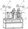
图1为本发明的立体结构示意图。 Fig. 1 is a schematic diagram of the three-dimensional structure of the present invention.
图2为本发明PIN针上料装置与PIN针夹取装置的立体结构示意图。 Fig. 2 is a three-dimensional structure schematic diagram of the PIN needle feeding device and the PIN needle clamping device of the present invention.
图3为本发明PIN针夹取装置的剖面结构示意图。 Fig. 3 is a schematic cross-sectional structure diagram of the PIN needle clamping device of the present invention.
图4为本发明PIN针夹取装置的调整机构的结构示意图。 Fig. 4 is a structural schematic diagram of the adjustment mechanism of the PIN needle clamping device of the present invention.
图5为本发明PIN针推料机构和PIN针固定机构的右视图。 Fig. 5 is a right view of the PIN needle pushing mechanism and the PIN needle fixing mechanism of the present invention.
图6为本发明PIN针固定装置的立体结构示意图。 FIG. 6 is a schematic diagram of a three-dimensional structure of the PIN needle fixing device of the present invention.
图7为本发明PIN针推料机构的分解结构示意图。 Fig. 7 is a schematic diagram of an exploded structure of the PIN needle pushing mechanism of the present invention.
图8为本发明推料装置的立体结构示意图。 Fig. 8 is a schematic perspective view of the three-dimensional structure of the pushing device of the present invention.
附图标记为: The reference signs are:
1—料带放料轮组 2—PIN针上料装置 21—PIN针上料通道
1—Belt
3—PIN针夹取装置 31—第一支柱 32—夹座
3—PIN
321—针板 322—调整顶针 331—推板 332—基座
321—
333—第一驱动气缸 334—第一支撑板 335—第一连杆
333—the
341—第二驱动气缸 342—第三驱动气缸 35—第一弹簧
341—the
361—第一压料板 362—第四驱动气缸 363—第二支撑板
361—the first
364—第二连杆 365—刀口 371—第五驱动气缸
364—Second connecting
372—第一驱动块 373—第一斜面 374—第一驱动轮
372—the
4—PIN针固定装置 41—第二支柱 42—第六驱动气缸
4—PIN
43—第三支柱 44—第一模座 441—第二容置槽
43—the
442—第二弹簧 45—针排 451—卡接槽
442—
452—第二斜面 461—卡接块 462—第七驱动气缸
452—
463—第三斜面 471—第二压料板 472—第八驱动气缸
463—the
473—第二驱动块 474—第四斜面 475—第二驱动轮
473—the
5—推料装置 51—第二模座 52—固定块 5—Pushing device 51—Second mold base 52—Fixed block
53—第九驱动气缸 54—定位针 6—料带收料轮组。
53—the ninth drive cylinder 54—locating
具体实施方式 Detailed ways
下面结合附图1至图8,以及具体实施方式对本发明做进一步地说明。
The present invention will be further described below with reference to the accompanying
如图1至图8所示,一种四方针端子打卡点机,包括机台,所述机台上端按照工序流程依次设置有料带放料轮组1、PIN针上料装置2、PIN针夹取装置3、驱动PIN针夹取装置3位移的传动机构、PIN针固定装置4、推料装置5及料带收料轮组6。
As shown in Figures 1 to 8, a four-pin terminal punching point machine includes a machine table, and the upper end of the machine table is sequentially provided with a material belt
本实施例减少了人工成本,降低生产成本,提高生产效率,并使PIN针与料带的连接更加紧密、牢固,延长连接器的使用寿命,降低连接器的报废率。 This embodiment reduces the labor cost, lowers the production cost, improves the production efficiency, and makes the connection between the PIN needle and the material tape more tightly and firmly, prolongs the service life of the connector, and reduces the scrap rate of the connector.
本实施例中,所述PIN针上料装置2包括振动盘和PIN针上料通道21,所述PIN针上料通道21的进料口与振动盘的出料口连接,所述PIN针上料通道21的出料口与PIN针夹取装置3连接,PIN针通过振动盘再进入PIN针上料通道21内,再进入PIN针夹取装置3。
In this embodiment, the PIN
如图2和图3,本实施例中,所述PIN针夹取装置3包括第一支柱31,所述第一支柱31的中部设置夹座32,所述夹座32内设置有针板321,所述第一支柱31的上部设置有打卡点机构,所述第一支柱31的底部设置有错料机构,所述针板321设置有容置PIN针的第一容置槽,所述错料机构包括推板331及驱动推板331上下移动的驱动机构,所述推板331的顶端与针板321的底端抵接,所述驱动机构包括设置于第一支柱底部的基座332,所述基座332设置有第一驱动气缸333及第一支撑板334,所述第一驱动气缸333与推板331之间设置第一连杆335,所述第一连杆335的一端与推板331的底端铰接,第一驱动气缸333的活塞杆穿过基座332的底板与第一连杆335的另一端铰接,所述第一支撑板334的底端与第一连杆335的中部铰接,所述第一支柱31的底板设置有第二驱动气缸341和第三驱动气缸342,所述第二驱动气缸341和第三驱动气缸342与基座332的底板连接,第二驱动气缸341和第三驱动气缸342的活塞杆做收缩动作,第一驱动气缸333的伸出动作,第一支撑板334相当于一个支点,使得第一连杆335与推板331连接的那一端向上运动,从而带动推板331向上运动,推板331在向上运动的过程中使夹座32翘起,从而使得针板321内的PIN针与PIN针上料通道21内的PIN针错开,PIN针上料通道21的出料口暂时被堵住,实现错料。
As shown in Fig. 2 and Fig. 3, in the present embodiment, the PIN
本实施例中,所述基座332的底板与第一支柱31之间设置有第一弹簧35,第二驱动气缸341和第三驱动气缸342的活塞杆做伸出动作,第一驱动气缸333的收缩动作,这里第一弹簧35起辅助作用,第一弹簧35恢复形变,使推板331向下运动,针板321与PIN针上料通道21平行,针板321的进料口与PIN针上料通道21出料口连通。
In this embodiment, a
本实施例中,所述打卡点机构包括第一压料板361、设置于第一支柱31上部的第四驱动气缸362及第二支撑板363,所述第一压料板361的底端与针板321的顶端抵接,所述第一压料板361与第四驱动气缸362之间设置有第二连杆364,所述第二连杆364的一端与第一压料板361的顶端铰接,所述第二连杆364的另一端与第四驱动气缸362的活塞杆铰接,所述第二支撑板363的顶端与第二连杆364的中部铰接,所述第一压料板361与针板321的抵接部设置有用于打卡点的刀口365,第四驱动气缸362的活塞杆做伸出动作,第二支撑板363相当于一个支点,第二连杆364与第一压料板361连接的一端向下运动,带动第一压料板361下压,实现刀口365在PIN针上打凸点,增强PIN针的牢固性。
In this embodiment, the punching point mechanism includes a first
本实施例中,所述PIN针夹取装置3还包括调整机构,所述调整机构包括设置于夹座32侧端的第五驱动气缸371,所述第五驱动气缸371的活塞杆连接有第一驱动块372,所述第一驱动块372开设有第一斜面373,所述夹座32的底端设置有第一驱动轮374,所述第一驱动轮374与第一驱动块372抵接,跟据PIN针材料长度的不同,可通过调整机构来调节在PIN针上打凸点的位置。
In this embodiment, the PIN
本实施例中,所述PIN针固定装置4包括PIN针推料机构及PIN针固定机构,所述PIN针推料机构和PIN针固定机构之间设置有容下PIN针夹取装置3的间隔,所述PIN针推料机构包括第二支柱41,所述第二支柱41设置有驱动夹座32移动第六驱动气缸42,所述夹座32的上端设置有调整顶针322,打完凸点后,夹座32复位,传动机构将PIN针夹取装置3送至于PIN针推料机构和PIN针固定机构之间,第六驱动气缸42的活塞杆做伸出动作,推动夹座32移动,根据PIN针材料长度不同,可以通过调整顶针322来调节夹座32的行程,已达到调整PIN针与料带卡接位置的目的。
In the present embodiment, the PIN
如图5至图8,本实施例中,所述PIN针固定机构包括第三支柱43,所述第三支柱43的顶端设置有第一模座44,所述第一模座44的上端开设第一料槽,所述第一模座44的中部设置有第二容置槽441,所述第二容置槽441内设置有针排45,所述针排45与第二容置槽441的之间设置有第二弹簧442,所述针排45的中部开设有卡接槽451,所述第三支柱43还设置有锁死机构,所述锁死机构包括卡接块461及驱动卡接块461伸入卡接槽451内的第七驱动气缸462,所述卡接槽451开设有第二斜面452,所述卡接块461开设有第三斜面463,所述第二斜面452与第三斜面463滑动配合;所述针排45的上端设置有第二压料板471,所述第二压料板471的底端与针排45抵接,所述针排45的上方还设置有第八驱动气缸472,所述第八驱动气缸472的活塞杆连接有第二驱动块473,所述第二驱动块473开设有第四斜面474,所述第二压料板471的顶端铰接有第二驱动轮475,所述第二驱动块473与第二驱动轮475抵接,第六驱动气缸42将夹座32推出,针排45的上端同样设置有容置PIN针的容置槽,针板321上的PIN针被推入针排45上端的容置槽内,第八驱动气缸472的活塞杆做伸出动作,将第二压料板471向下压,第二压料板471将针排45完全压入第二容置槽441内,针排45上端的容置槽与第一模座44的上端的第一料槽对齐,第七驱动气缸462的活塞杆做伸出动作,将卡接块461伸入卡接槽451内,使针排45卡设于第二容置槽441内,不会复位,这样方便以卡入PIN针的料带位移,针排45上端的容置槽内的料带被推料装置5拖离后,第七驱动气缸462的活塞杆做收缩动作,卡接块461从卡接槽451退出,第二弹簧442恢复形变将针排45从第二容置槽441内顶出,重复循环工作。
As shown in Figures 5 to 8, in this embodiment, the PIN needle fixing mechanism includes a
本实施例中,所述推料装置5包括第二模座51,所述第二模座51开设有与第一料槽连通的第二料槽,所述第二料槽的上方设置推料机构,所述推料机构包括固定块52及驱动固定块52移动的第九驱动气缸53,所述固定块52设置有定位针54,所述定位针54位于第二料槽的正上方,料带的中间位置设有通孔,定位针54伸入通孔内,第九驱动气缸53再驱动固定块52移动,从而实现将针排45上端的容置槽内的料带拖离,固定块52移动的距离等于针排45的长度。
In this embodiment, the pushing
以上内容仅为本发明的较佳实施例,对于本领域的普通技术人员,依据本发明的思想,在具体实施方式及应用范围上均会有改变之处,本说明书内容不应理解为对本发明的限制。 The above content is only a preferred embodiment of the present invention. For those of ordinary skill in the art, according to the idea of the present invention, there will be changes in the specific implementation and application scope. limits.
Claims (9)
Priority Applications (1)
| Application Number | Priority Date | Filing Date | Title |
|---|---|---|---|
| CN201410124834.3A CN103855583B (en) | 2014-03-31 | 2014-03-31 | A kind of four policy terminals are checked card a machine |
Applications Claiming Priority (1)
| Application Number | Priority Date | Filing Date | Title |
|---|---|---|---|
| CN201410124834.3A CN103855583B (en) | 2014-03-31 | 2014-03-31 | A kind of four policy terminals are checked card a machine |
Publications (2)
| Publication Number | Publication Date |
|---|---|
| CN103855583A true CN103855583A (en) | 2014-06-11 |
| CN103855583B CN103855583B (en) | 2016-03-30 |
Family
ID=50862930
Family Applications (1)
| Application Number | Title | Priority Date | Filing Date |
|---|---|---|---|
| CN201410124834.3A Active CN103855583B (en) | 2014-03-31 | 2014-03-31 | A kind of four policy terminals are checked card a machine |
Country Status (1)
| Country | Link |
|---|---|
| CN (1) | CN103855583B (en) |
Cited By (4)
| Publication number | Priority date | Publication date | Assignee | Title |
|---|---|---|---|---|
| CN105252655A (en) * | 2015-11-19 | 2016-01-20 | 付瑞兰 | Special cutter for bevel angle |
| CN105846278A (en) * | 2016-05-26 | 2016-08-10 | 东莞市维峰五金电子有限公司 | Multi-functional row needle assembly machine |
| CN107394561A (en) * | 2017-06-22 | 2017-11-24 | 浙江松成电子有限公司 | Full-automatic AV socket production lines |
| CN108011280A (en) * | 2018-01-16 | 2018-05-08 | 乔讯电子(上海)有限公司 | A kind of automatic needle inserting machine |
Citations (3)
| Publication number | Priority date | Publication date | Assignee | Title |
|---|---|---|---|---|
| CN102427198A (en) * | 2011-12-28 | 2012-04-25 | 苏州市金松精密电子有限公司 | Dotting device for terminal processing |
| CN103346457A (en) * | 2013-06-26 | 2013-10-09 | 宁波兴瑞电子有限公司 | F socket shell body dotting machine |
| CN203774588U (en) * | 2014-03-31 | 2014-08-13 | 东莞市维峰五金电子有限公司 | Square pin terminal clamp point punching machine |
-
2014
- 2014-03-31 CN CN201410124834.3A patent/CN103855583B/en active Active
Patent Citations (3)
| Publication number | Priority date | Publication date | Assignee | Title |
|---|---|---|---|---|
| CN102427198A (en) * | 2011-12-28 | 2012-04-25 | 苏州市金松精密电子有限公司 | Dotting device for terminal processing |
| CN103346457A (en) * | 2013-06-26 | 2013-10-09 | 宁波兴瑞电子有限公司 | F socket shell body dotting machine |
| CN203774588U (en) * | 2014-03-31 | 2014-08-13 | 东莞市维峰五金电子有限公司 | Square pin terminal clamp point punching machine |
Cited By (4)
| Publication number | Priority date | Publication date | Assignee | Title |
|---|---|---|---|---|
| CN105252655A (en) * | 2015-11-19 | 2016-01-20 | 付瑞兰 | Special cutter for bevel angle |
| CN105846278A (en) * | 2016-05-26 | 2016-08-10 | 东莞市维峰五金电子有限公司 | Multi-functional row needle assembly machine |
| CN107394561A (en) * | 2017-06-22 | 2017-11-24 | 浙江松成电子有限公司 | Full-automatic AV socket production lines |
| CN108011280A (en) * | 2018-01-16 | 2018-05-08 | 乔讯电子(上海)有限公司 | A kind of automatic needle inserting machine |
Also Published As
| Publication number | Publication date |
|---|---|
| CN103855583B (en) | 2016-03-30 |
Similar Documents
| Publication | Publication Date | Title |
|---|---|---|
| CN204885785U (en) | Fully automatic wire harness wear waterproof plug crimping terminal machine with waterproof plug device | |
| CN103855583B (en) | A kind of four policy terminals are checked card a machine | |
| CN206961953U (en) | A battery automatic needle tube device | |
| CN110480314A (en) | A kind of automatic riveting machine | |
| CN108356524A (en) | A kind of automatic assembling of toy doll ejection gun barrel | |
| CN108994197B (en) | Automatic stamping equipment of car door hinge | |
| CN107516598A (en) | A terminal pin insertion mechanism for a double-skeleton coil | |
| CN203707548U (en) | Automatic crimping device for wire rods | |
| CN208906268U (en) | A kind of rectangular tube automatic feeding | |
| CN203774588U (en) | Square pin terminal clamp point punching machine | |
| CN207818822U (en) | A lithium battery bottom cover automatic feeding mechanism | |
| CN112170706B (en) | A bending device for electronic device pins | |
| CN103413677B (en) | The shaping shearing of full-automatic vertical inductance component pin detects all-in-one | |
| CN103111531B (en) | Automatic terminal support riveting copper ingot device and riveting copper ingot method thereof | |
| CN109773454A (en) | A kind of automatic pin pressing machine for piston | |
| CN205165439U (en) | Take ejection mechanism's bender | |
| CN209823081U (en) | Tool is put to PIN needle class product | |
| CN209794391U (en) | Robot automatic buried PIN device | |
| CN209183422U (en) | A kind of contact pin assembly machine of toggle switch | |
| CN207139203U (en) | One kind is oriented to pin bush(ing) automatic installation apparatus | |
| CN203553601U (en) | DC power plug assembly machine | |
| CN215242826U (en) | Injection product machine-shaping device | |
| CN208461184U (en) | A kind of automatic riveting line machine | |
| CN205510665U (en) | Plug -in components head mechanism of plug -in components machine | |
| CN210678982U (en) | Automatic punching, bending and disc placing machine for plastic main frame of mobile phone loudspeaker |
Legal Events
| Date | Code | Title | Description |
|---|---|---|---|
| C06 | Publication | ||
| PB01 | Publication | ||
| C10 | Entry into substantive examination | ||
| SE01 | Entry into force of request for substantive examination | ||
| C14 | Grant of patent or utility model | ||
| GR01 | Patent grant | ||
| PE01 | Entry into force of the registration of the contract for pledge of patent right | ||
| PE01 | Entry into force of the registration of the contract for pledge of patent right |
Denomination of invention: Stuck-point striking machine for square pin terminals Effective date of registration: 20180316 Granted publication date: 20160330 Pledgee: China Co. truction Bank Corp Dongguan Changan branch Pledgor: DONGGUAN WEIFENG HARDWARE ELECTRONICS PRODUCTS Co.,Ltd. Registration number: 2018440000057 |
|
| CP03 | Change of name, title or address | ||
| CP03 | Change of name, title or address |
Address after: 523000 01A, Changxing Road, Ludong community, Humen Town, Dongguan City, Guangdong Province Patentee after: Weifeng electronic (Guangdong) Co.,Ltd. Address before: 523860 Guangdong city of Dongguan province Changan town community South Road Sha Boye Industrial Park building F Patentee before: DONGGUAN WEIFENG HARDWARE ELECTRONICS PRODUCTS Co.,Ltd. |
|
| PC01 | Cancellation of the registration of the contract for pledge of patent right | ||
| PC01 | Cancellation of the registration of the contract for pledge of patent right |
Date of cancellation: 20210311 Granted publication date: 20160330 Pledgee: China Co. truction Bank Corp Dongguan Changan branch Pledgor: DONGGUAN WEIFENG HARDWARE ELECTRONICS PRODUCTS Co.,Ltd. Registration number: 2018440000057 |
|
| CP03 | Change of name, title or address | ||
| CP03 | Change of name, title or address |
Address after: No. 15, Wenming Road, Daning, Humen Town, Dongguan City, Guangdong Province, 523000 Patentee after: Weifeng electronic (Guangdong) Co.,Ltd. Country or region after: China Address before: 523000 01A, Changxing Road, Ludong community, Humen Town, Dongguan City, Guangdong Province Patentee before: Weifeng electronic (Guangdong) Co.,Ltd. Country or region before: China |
|
| CP03 | Change of name, title or address | ||
| CP03 | Change of name, title or address |
Address after: No. 15, Wenming Road, Daning, Humen Town, Dongguan City, Guangdong Province, 523000 Patentee after: Weifeng Electronics Co.,Ltd. Country or region after: China Address before: No. 15, Wenming Road, Daning, Humen Town, Dongguan City, Guangdong Province, 523000 Patentee before: Weifeng electronic (Guangdong) Co.,Ltd. Country or region before: China |