CN103801742A - Automatic gate milling machine - Google Patents
Automatic gate milling machine Download PDFInfo
- Publication number
- CN103801742A CN103801742A CN201410099705.3A CN201410099705A CN103801742A CN 103801742 A CN103801742 A CN 103801742A CN 201410099705 A CN201410099705 A CN 201410099705A CN 103801742 A CN103801742 A CN 103801742A
- Authority
- CN
- China
- Prior art keywords
- plate
- slide rail
- workpiece location
- axis
- main shaft
- Prior art date
- Legal status (The legal status is an assumption and is not a legal conclusion. Google has not performed a legal analysis and makes no representation as to the accuracy of the status listed.)
- Granted
Links
- 238000003801 milling Methods 0.000 title claims abstract description 26
- 230000006835 compression Effects 0.000 claims description 11
- 238000007906 compression Methods 0.000 claims description 11
- 230000017105 transposition Effects 0.000 claims description 7
- 230000035611 feeding Effects 0.000 description 7
- 230000009286 beneficial effect Effects 0.000 description 3
- 238000003754 machining Methods 0.000 description 3
- 238000004140 cleaning Methods 0.000 description 2
- 238000000034 method Methods 0.000 description 2
- 230000004048 modification Effects 0.000 description 2
- 238000012986 modification Methods 0.000 description 2
- 238000010923 batch production Methods 0.000 description 1
- 230000005540 biological transmission Effects 0.000 description 1
- 238000006243 chemical reaction Methods 0.000 description 1
- 238000010586 diagram Methods 0.000 description 1
- 230000000694 effects Effects 0.000 description 1
- 238000005516 engineering process Methods 0.000 description 1
- 238000009434 installation Methods 0.000 description 1
- 238000000465 moulding Methods 0.000 description 1
Images


Abstract
The invention discloses an automatic gate milling machine, comprising a compressing cylinder, a spindle motor and a feeding mechanism, wherein the compressing cylinder is arranged above a work-piece locating plate; the spindle motor is arranged below the work-piece locating plate; the feeding mechanism drives the spindle motor to feed; an avoiding hole is formed in the work-piece locating plate; a spindle and a milling cutter are orderly connected to the spindle motor; the avoiding hole overlaps with the axis of the spindle; the axis of the spindle, the axis of the compressing cylinder and the feeding mechanism are parallel in direction. The work-piece locating plate is arranged on the automatic gate milling machine, a locating groove is formed inside the locating plate, and the device is clamped by adopting the compressing cylinder, so that the automatic gate milling machine is reliable to clamp and high in automatic processing efficiency, and the labor intensity of a worker is reduced.
Description
Technical field
The present invention relates to a kind of milling cast gate machine automatically.
Background technology
Cup-shaped moulding needs milling cast gate, and existing method is to adopt vertical knee-type milling machine, and workpiece is placed on workbench and pins and directly carry out manual milling with hand, and the shortcoming of prior art is: 1) there is no special positioning and clamping mechanism, it is unreliable to clamp; 2), there is potential safety hazard in manual operation; 3), location on the other hand, a hand operated, causes Milling Accuracy not high, 4) when batch production, working (machining) efficiency is low; 5) because cast gate is positioned at housing bottom die cavity, and vertical milling machine main is above workpiece, chip removal inconvenience.
Summary of the invention
The object of the invention is to overcome the above problem that prior art exists, a kind of milling cast gate machine is automatically provided, realize milling automatic, improve machining accuracy and operating efficiency.
For realizing above-mentioned technical purpose, reach above-mentioned technique effect, the present invention is achieved through the following technical solutions:
A kind of milling cast gate machine automatically, comprise and be arranged at the compression cylinder of workpiece location-plate top, the spindle motor that is arranged at workpiece location-plate below and the feed mechanism of drives spindle motor feeding, on described workpiece location-plate, offer and dodge hole, on described spindle motor, be connected with main shaft and milling cutter in turn, described hole and the described main-shaft axis of dodging overlaps, and described main-shaft axis, described compression cylinder axis are parallel with described feed mechanism direction of feed.
Further, described feed mechanism comprises the feed screw nut on screw mandrel, the screw mandrel being connected on feeding motor and is connected to the upper lift slide for fixed main shaft motor of feed screw nut, lift slide both sides are provided with the first slide rail, described screw mandrel, described main shaft and described the first slide rail axis are parallel, and described screw mandrel, described the first slide rail are connected to described workpiece location-plate below by feed mechanism fixed head.
Preferably, described workpiece location-plate one end is connected with the transposition cylinder of horizontal positioned, offers at least two locating slots on workpiece location-plate, and hole is dodged described in being in described locating slot center, workpiece location-plate both sides are provided with the second slide rail, and described transposition cylinder-bore axis is parallel with described the second slide rail axis.
Preferably, the described first slide rail two ends of a side are provided with the first limit switch.
Preferably, the described second slide rail two ends of a side are provided with the second limit switch.
Further, described workpiece location-plate is positioned on work top, and described compression cylinder is fixed on described work top by column.
The invention has the beneficial effects as follows:
1) be provided with workpiece location-plate, in location-plate, offer locating slot, and adopt compression cylinder clamping device, reliable clamping.
2) it is simple in structure that feed mechanism adopts the motor-driven screw body of feeding, and transmission accuracy is high, good operating stability.
3) be provided with installation and removal station, workman only need be placed on workpiece on load/unload stations, and all the other all complete automatically, and efficiency, security are all improved.
4) automation working (machining) efficiency is high, and labor strength reduces.
5) main shaft is positioned at workpiece below, is beneficial to chip removal, removes labor cleaning's operation from.
Above-mentioned explanation is only the general introduction of technical solution of the present invention, in order to better understand technological means of the present invention, and can be implemented according to the content of description, below with preferred embodiment of the present invention and coordinate accompanying drawing to be described in detail as follows.The specific embodiment of the present invention is provided in detail by following examples and accompanying drawing thereof.
Accompanying drawing explanation
Accompanying drawing described herein is used to provide a further understanding of the present invention, forms the application's a part, and schematic description and description of the present invention is used for explaining the present invention, does not form inappropriate limitation of the present invention.In the accompanying drawings:
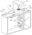
Fig. 1 is automatic milling cast gate machine overall structure schematic diagram;
Fig. 2 is feed mechanism structural representation;
Fig. 3 is work top structural representation.
Number in the figure explanation: 1, workpiece location-plate, 100, work top, 101, dodge hole, 102, locating slot, 103, transposition cylinder, 104, the second slide rail, 105, the second limit switch, 2, compression cylinder, 201, column, 3, spindle motor, 301, main shaft, 4, feed mechanism, 400, feed mechanism fixed head, 401, feeding motor, 402, screw mandrel, 403, lift slide, 404, the first slide rail, 405, the first limit switch.
The specific embodiment
Below with reference to the accompanying drawings and in conjunction with the embodiments, describe the present invention in detail.
Shown in Fig. 1, Fig. 3, a kind of milling cast gate machine automatically, comprise the feed mechanism 4 that is arranged at the compression cylinder 2 of workpiece location-plate 1 top, the spindle motor 3 that is arranged at workpiece location-plate 1 below and drives spindle motor 3 feedings, on described workpiece location-plate 1, offer and dodge hole 101, on described spindle motor 3, be connected with main shaft 301 and milling cutter in turn, describedly dodge hole 101 and 301 deads in line of described main shaft, described main shaft 301 axis, described compression cylinder 2 axis are parallel with described feed mechanism 4 directions of feed.Main shaft 301 is arranged at workpiece below, is beneficial to chip removal, removes labor cleaning's operation from.
Shown in Fig. 2, described feed mechanism 4 comprises the feed screw nut on screw mandrel 402, the screw mandrel 402 being connected on feeding motor 401 and is connected to the upper lift slide 403 for fixed main shaft motor 3 of feed screw nut, lift slide 403 both sides are provided with the first slide rail 404, described screw mandrel 402, described main shaft 301 and described the first slide rail 404 axis are parallel, and described screw mandrel 402, described the first slide rail 404 are connected to described workpiece location-plate 1 below by feed mechanism fixed head 400.For controlling automatically, accurately the feeding of main shaft, described first slide rail 404 two ends of a side are provided with the first limit switch 405.
Shown in Fig. 1, described workpiece location-plate 1 one end is connected with the transposition cylinder 103 of horizontal positioned, on workpiece location-plate 1, offer at least two locating slots 102, hole 101 is dodged described in being in described locating slot 102 centers, workpiece location-plate 1 both sides are provided with the second slide rail 104, and described transposition cylinder 103 axis are parallel with described the second slide rail 104 axis.For controlling automatically, accurately the conversion of station, described second slide rail 104 two ends of a side are provided with the second limit switch 105.
Shown in Fig. 1, described workpiece location-plate 1 is positioned on work top 100, and described compression cylinder 2 is fixed on described work top 100 by column 201.
The foregoing is only the preferred embodiments of the present invention, be not limited to the present invention, for a person skilled in the art, the present invention can have various modifications and variations.Within the spirit and principles in the present invention all, any modification of doing, be equal to replacement, improvement etc., within all should being included in protection scope of the present invention.
Claims (6)
1. an automatic milling cast gate machine, it is characterized in that: comprise the compression cylinder (2) that is arranged at workpiece location-plate (1) top, be arranged at the spindle motor (3) of workpiece location-plate (1) below and the feed mechanism (4) of drives spindle motor (3) feeding, on described workpiece location-plate (1), offer and dodge hole (101), on described spindle motor (3), be connected with main shaft (301) and milling cutter in turn, describedly dodge hole (101) and described main shaft (301) dead in line, described main shaft (301) axis, described compression cylinder (2) axis is parallel with described feed mechanism (4) direction of feed.
2. automatic milling cast gate machine according to claim 1, it is characterized in that: described feed mechanism (4) comprises the screw mandrel (402) being connected on feeding motor (401), feed screw nut on screw mandrel (402) and be connected to the upper lift slide (403) for fixed main shaft motor (3) of feed screw nut, lift slide (403) both sides are provided with the first slide rail (404), described screw mandrel (402), described main shaft (301) and described the first slide rail (404) axis are parallel, described screw mandrel (402), described the first slide rail (404) is connected to described workpiece location-plate (1) below by feed mechanism fixed head (400).
3. automatic milling cast gate machine according to claim 1, it is characterized in that: described workpiece location-plate (1) one end is connected with the transposition cylinder (103) of horizontal positioned, on workpiece location-plate (1), offer at least two locating slots (102), hole (101) is dodged described in being in described locating slot (102) center, workpiece location-plate (1) both sides are provided with the second slide rail (104), and described transposition cylinder (103) axis is parallel with described the second slide rail (104) axis.
4. automatic milling cast gate machine according to claim 2, is characterized in that: described the first slide rail (404) two ends of a side are provided with the first limit switch (405).
5. automatic milling cast gate machine according to claim 3, is characterized in that: described the second slide rail (104) two ends of a side are provided with the second limit switch (105).
6. automatic milling cast gate machine according to claim 1, is characterized in that: it is upper that described workpiece location-plate (1) is positioned over work top (100), and described compression cylinder (2) is fixed on described work top (100) by column (201).
Priority Applications (1)
| Application Number | Priority Date | Filing Date | Title |
|---|---|---|---|
| CN201410099705.3A CN103801742B (en) | 2014-03-18 | 2014-03-18 | Automatically milling cast gate machine |
Applications Claiming Priority (1)
| Application Number | Priority Date | Filing Date | Title |
|---|---|---|---|
| CN201410099705.3A CN103801742B (en) | 2014-03-18 | 2014-03-18 | Automatically milling cast gate machine |
Publications (2)
| Publication Number | Publication Date |
|---|---|
| CN103801742A true CN103801742A (en) | 2014-05-21 |
| CN103801742B CN103801742B (en) | 2016-05-04 |
Family
ID=50699393
Family Applications (1)
| Application Number | Title | Priority Date | Filing Date |
|---|---|---|---|
| CN201410099705.3A Active CN103801742B (en) | 2014-03-18 | 2014-03-18 | Automatically milling cast gate machine |
Country Status (1)
| Country | Link |
|---|---|
| CN (1) | CN103801742B (en) |
Cited By (5)
| Publication number | Priority date | Publication date | Assignee | Title |
|---|---|---|---|---|
| CN104174916A (en) * | 2014-08-07 | 2014-12-03 | 浙江锦盛包装有限公司 | Burning mouth milling machine and using method thereof |
| CN105058140A (en) * | 2015-09-21 | 2015-11-18 | 蓬莱巨涛海洋工程重工有限公司 | In-situ strip hole processing machine |
| CN106348225A (en) * | 2016-10-03 | 2017-01-25 | 王杨 | Movable lifting device for cutting |
| CN107932846A (en) * | 2017-12-26 | 2018-04-20 | 张家港中天精密模塑有限公司 | A kind of injection molding impeller removes gate mechanism |
| CN110039469A (en) * | 2019-04-30 | 2019-07-23 | 上海诣谱自动化装备有限公司 | A kind of tooling being easily installed different automobile types fixture |
Citations (8)
| Publication number | Priority date | Publication date | Assignee | Title |
|---|---|---|---|---|
| JPH1024450A (en) * | 1996-07-12 | 1998-01-27 | Murata Mach Ltd | Gate cut part processing system |
| CN201008938Y (en) * | 2006-12-05 | 2008-01-23 | 亨特尔(天津)科技开发有限公司 | Milling mechanism with adjustable sprue |
| CN102689420A (en) * | 2011-03-23 | 2012-09-26 | 汉达精密电子(昆山)有限公司 | In-mold gate automatic resection mechanism |
| CN202701979U (en) * | 2012-07-05 | 2013-01-30 | 无锡鹰普精密铸造有限公司 | Automatic cutting machine |
| CN202895614U (en) * | 2012-05-16 | 2013-04-24 | 江苏常诚汽车部件有限公司 | Mold gate automatic-cutting device |
| CN202934770U (en) * | 2012-11-30 | 2013-05-15 | 嘉善蓝创塑胶有限公司 | Trimming jig for molded part annular feed port |
| CN203092966U (en) * | 2012-12-12 | 2013-07-31 | 汉达精密电子(昆山)有限公司 | Automatic reverse milling mechanism |
| CN203738096U (en) * | 2014-03-18 | 2014-07-30 | 苏州工业职业技术学院 | Automatic pouring gate milling machine |
-
2014
- 2014-03-18 CN CN201410099705.3A patent/CN103801742B/en active Active
Patent Citations (8)
| Publication number | Priority date | Publication date | Assignee | Title |
|---|---|---|---|---|
| JPH1024450A (en) * | 1996-07-12 | 1998-01-27 | Murata Mach Ltd | Gate cut part processing system |
| CN201008938Y (en) * | 2006-12-05 | 2008-01-23 | 亨特尔(天津)科技开发有限公司 | Milling mechanism with adjustable sprue |
| CN102689420A (en) * | 2011-03-23 | 2012-09-26 | 汉达精密电子(昆山)有限公司 | In-mold gate automatic resection mechanism |
| CN202895614U (en) * | 2012-05-16 | 2013-04-24 | 江苏常诚汽车部件有限公司 | Mold gate automatic-cutting device |
| CN202701979U (en) * | 2012-07-05 | 2013-01-30 | 无锡鹰普精密铸造有限公司 | Automatic cutting machine |
| CN202934770U (en) * | 2012-11-30 | 2013-05-15 | 嘉善蓝创塑胶有限公司 | Trimming jig for molded part annular feed port |
| CN203092966U (en) * | 2012-12-12 | 2013-07-31 | 汉达精密电子(昆山)有限公司 | Automatic reverse milling mechanism |
| CN203738096U (en) * | 2014-03-18 | 2014-07-30 | 苏州工业职业技术学院 | Automatic pouring gate milling machine |
Cited By (5)
| Publication number | Priority date | Publication date | Assignee | Title |
|---|---|---|---|---|
| CN104174916A (en) * | 2014-08-07 | 2014-12-03 | 浙江锦盛包装有限公司 | Burning mouth milling machine and using method thereof |
| CN105058140A (en) * | 2015-09-21 | 2015-11-18 | 蓬莱巨涛海洋工程重工有限公司 | In-situ strip hole processing machine |
| CN106348225A (en) * | 2016-10-03 | 2017-01-25 | 王杨 | Movable lifting device for cutting |
| CN107932846A (en) * | 2017-12-26 | 2018-04-20 | 张家港中天精密模塑有限公司 | A kind of injection molding impeller removes gate mechanism |
| CN110039469A (en) * | 2019-04-30 | 2019-07-23 | 上海诣谱自动化装备有限公司 | A kind of tooling being easily installed different automobile types fixture |
Also Published As
| Publication number | Publication date |
|---|---|
| CN103801742B (en) | 2016-05-04 |
Similar Documents
| Publication | Publication Date | Title |
|---|---|---|
| CN103801742B (en) | Automatically milling cast gate machine | |
| CN102756278A (en) | Automatic drilling, taping and chamfering machine | |
| CN205437155U (en) | Non -circular cross -section part turning lathe | |
| CN202539975U (en) | Angle-adjustable positioning device for inclined plane machining | |
| CN207447435U (en) | A kind of three facing cut machining tools | |
| CN204657587U (en) | A kind of edge milling machines | |
| CN207223450U (en) | A kind of automatic clamping-type fraise jig | |
| CN203236245U (en) | Workpiece base for numerical control machine tool | |
| CN203738096U (en) | Automatic pouring gate milling machine | |
| CN201815729U (en) | Cardan universal joint groove milling device | |
| CN204565642U (en) | Mould is from reducing grip device | |
| CN103100904B (en) | A kind of portable minisize aerodynamic force milling machine | |
| CN105150058A (en) | Grinding machine with automatic sudden stop function | |
| CN202861767U (en) | Automatic drilling tapping chamfering machine | |
| CN203853579U (en) | Radial drilling machine | |
| CN103737025B (en) | A kind of Digit Control Machine Tool processing sheet workpiece | |
| CN108746714A (en) | A kind of automatic drilling device of turning | |
| CN204182966U (en) | A kind of semi-automatic gas seat ring rough bore machine | |
| CN104015087B (en) | The processing pay-off of steel ball | |
| CN104057281B (en) | Rear sliding block riveting tooling | |
| CN220161073U (en) | Hydraulic punching machine | |
| CN214135000U (en) | Annular thin-walled piece cutting and clamping device | |
| CN220679124U (en) | Small-sized punching machine | |
| CN214602329U (en) | Spline machining equipment | |
| CN214721204U (en) | Nonstandard thread processing device |
Legal Events
| Date | Code | Title | Description |
|---|---|---|---|
| C06 | Publication | ||
| PB01 | Publication | ||
| C10 | Entry into substantive examination | ||
| SE01 | Entry into force of request for substantive examination | ||
| C14 | Grant of patent or utility model | ||
| GR01 | Patent grant | ||
| TR01 | Transfer of patent right | ||
| TR01 | Transfer of patent right |
Effective date of registration: 20231120 Address after: 215000 first floor, building e, No. 58, Yangdong Road, loufengbei District, Suzhou Industrial Park, Jiangsu Province Patentee after: Taicheng semiconductor precision (Suzhou) Co.,Ltd. Address before: 215000 No. 1 Zhineng Avenue, Wuzhong Avenue International Education Park, Suzhou, Jiangsu Patentee before: Suzhou Vocational Institute of Industrial Technology |