CN103726518A - Multifunctional all-terrain walking type hydraulic excavator - Google Patents

Multifunctional all-terrain walking type hydraulic excavator Download PDF

Info

Publication number
CN103726518A
CN103726518A CN201410011760.2A CN201410011760A CN103726518A CN 103726518 A CN103726518 A CN 103726518A CN 201410011760 A CN201410011760 A CN 201410011760A CN 103726518 A CN103726518 A CN 103726518A
Authority
CN
China
Prior art keywords
leg
walking
hydraulic
dipper
hydraulic jack
Prior art date
Legal status (The legal status is an assumption and is not a legal conclusion. Google has not performed a legal analysis and makes no representation as to the accuracy of the status listed.)
Granted
Application number
CN201410011760.2A
Other languages
Chinese (zh)
Other versions
CN103726518B (en
Inventor
陈秀峰
施晓明
薛峰
许敬科
张云
邬俊奇
曹永�
高然
张�杰
张丽平
王福德
刘磊
刘玉香
魏宇明
朱凯
魏雪峰
彭之晗
丁联凤
韩静
刘静
Current Assignee (The listed assignees may be inaccurate. Google has not performed a legal analysis and makes no representation or warranty as to the accuracy of the list.)
Xuzhou XCMG Road Construction Machinery Co Ltd
Original Assignee
Xuzhou XCMG Road Construction Machinery Co Ltd
Priority date (The priority date is an assumption and is not a legal conclusion. Google has not performed a legal analysis and makes no representation as to the accuracy of the date listed.)
Filing date
Publication date
Application filed by Xuzhou XCMG Road Construction Machinery Co Ltd filed Critical Xuzhou XCMG Road Construction Machinery Co Ltd
Priority to CN201410011760.2A priority Critical patent/CN103726518B/en
Publication of CN103726518A publication Critical patent/CN103726518A/en
Priority to PCT/CN2015/070317 priority patent/WO2015103985A1/en
Application granted granted Critical
Publication of CN103726518B publication Critical patent/CN103726518B/en
Priority to US15/206,883 priority patent/US20160319513A1/en
Priority to ZA2016/04850A priority patent/ZA201604850B/en
Active legal-status Critical Current
Anticipated expiration legal-status Critical

Links

Images

Classifications

    • E—FIXED CONSTRUCTIONS
    • E02—HYDRAULIC ENGINEERING; FOUNDATIONS; SOIL SHIFTING
    • E02F—DREDGING; SOIL-SHIFTING
    • E02F9/00—Component parts of dredgers or soil-shifting machines, not restricted to one of the kinds covered by groups E02F3/00 - E02F7/00
    • E02F9/02—Travelling-gear, e.g. associated with slewing gears
    • E02F9/024—Travelling-gear, e.g. associated with slewing gears with laterally or vertically adjustable wheels or tracks
    • E—FIXED CONSTRUCTIONS
    • E02—HYDRAULIC ENGINEERING; FOUNDATIONS; SOIL SHIFTING
    • E02F—DREDGING; SOIL-SHIFTING
    • E02F3/00—Dredgers; Soil-shifting machines
    • E02F3/04—Dredgers; Soil-shifting machines mechanically-driven
    • E02F3/28—Dredgers; Soil-shifting machines mechanically-driven with digging tools mounted on a dipper- or bucket-arm, i.e. there is either one arm or a pair of arms, e.g. dippers, buckets
    • E02F3/30—Dredgers; Soil-shifting machines mechanically-driven with digging tools mounted on a dipper- or bucket-arm, i.e. there is either one arm or a pair of arms, e.g. dippers, buckets with a dipper-arm pivoted on a cantilever beam, i.e. boom
    • E02F3/306—Dredgers; Soil-shifting machines mechanically-driven with digging tools mounted on a dipper- or bucket-arm, i.e. there is either one arm or a pair of arms, e.g. dippers, buckets with a dipper-arm pivoted on a cantilever beam, i.e. boom with telescopic dipper-arm or boom
    • E—FIXED CONSTRUCTIONS
    • E02—HYDRAULIC ENGINEERING; FOUNDATIONS; SOIL SHIFTING
    • E02F—DREDGING; SOIL-SHIFTING
    • E02F3/00—Dredgers; Soil-shifting machines
    • E02F3/04—Dredgers; Soil-shifting machines mechanically-driven
    • E02F3/28—Dredgers; Soil-shifting machines mechanically-driven with digging tools mounted on a dipper- or bucket-arm, i.e. there is either one arm or a pair of arms, e.g. dippers, buckets
    • E02F3/30—Dredgers; Soil-shifting machines mechanically-driven with digging tools mounted on a dipper- or bucket-arm, i.e. there is either one arm or a pair of arms, e.g. dippers, buckets with a dipper-arm pivoted on a cantilever beam, i.e. boom
    • E02F3/32—Dredgers; Soil-shifting machines mechanically-driven with digging tools mounted on a dipper- or bucket-arm, i.e. there is either one arm or a pair of arms, e.g. dippers, buckets with a dipper-arm pivoted on a cantilever beam, i.e. boom working downwardly and towards the machine, e.g. with backhoes
    • E02F3/325—Backhoes of the miniature type
    • E—FIXED CONSTRUCTIONS
    • E02—HYDRAULIC ENGINEERING; FOUNDATIONS; SOIL SHIFTING
    • E02F—DREDGING; SOIL-SHIFTING
    • E02F3/00—Dredgers; Soil-shifting machines
    • E02F3/04—Dredgers; Soil-shifting machines mechanically-driven
    • E02F3/28—Dredgers; Soil-shifting machines mechanically-driven with digging tools mounted on a dipper- or bucket-arm, i.e. there is either one arm or a pair of arms, e.g. dippers, buckets
    • E02F3/36—Component parts
    • E02F3/3604—Devices to connect tools to arms, booms or the like
    • E02F3/3609—Devices to connect tools to arms, booms or the like of the quick acting type, e.g. controlled from the operator seat
    • E—FIXED CONSTRUCTIONS
    • E02—HYDRAULIC ENGINEERING; FOUNDATIONS; SOIL SHIFTING
    • E02F—DREDGING; SOIL-SHIFTING
    • E02F3/00—Dredgers; Soil-shifting machines
    • E02F3/04—Dredgers; Soil-shifting machines mechanically-driven
    • E02F3/28—Dredgers; Soil-shifting machines mechanically-driven with digging tools mounted on a dipper- or bucket-arm, i.e. there is either one arm or a pair of arms, e.g. dippers, buckets
    • E02F3/36—Component parts
    • E02F3/38—Cantilever beams, i.e. booms;, e.g. manufacturing processes, forms, geometry or materials used for booms; Dipper-arms, e.g. manufacturing processes, forms, geometry or materials used for dipper-arms; Bucket-arms
    • E—FIXED CONSTRUCTIONS
    • E02—HYDRAULIC ENGINEERING; FOUNDATIONS; SOIL SHIFTING
    • E02F—DREDGING; SOIL-SHIFTING
    • E02F9/00—Component parts of dredgers or soil-shifting machines, not restricted to one of the kinds covered by groups E02F3/00 - E02F7/00
    • E02F9/02—Travelling-gear, e.g. associated with slewing gears
    • E02F9/028—Travelling-gear, e.g. associated with slewing gears with arrangements for levelling the machine
    • E—FIXED CONSTRUCTIONS
    • E02—HYDRAULIC ENGINEERING; FOUNDATIONS; SOIL SHIFTING
    • E02F—DREDGING; SOIL-SHIFTING
    • E02F9/00—Component parts of dredgers or soil-shifting machines, not restricted to one of the kinds covered by groups E02F3/00 - E02F7/00
    • E02F9/02—Travelling-gear, e.g. associated with slewing gears
    • E02F9/04—Walking gears moving the dredger forward step-by-step
    • E—FIXED CONSTRUCTIONS
    • E02—HYDRAULIC ENGINEERING; FOUNDATIONS; SOIL SHIFTING
    • E02F—DREDGING; SOIL-SHIFTING
    • E02F9/00—Component parts of dredgers or soil-shifting machines, not restricted to one of the kinds covered by groups E02F3/00 - E02F7/00
    • E02F9/08—Superstructures; Supports for superstructures
    • E02F9/085—Ground-engaging fitting for supporting the machines while working, e.g. outriggers, legs
    • E—FIXED CONSTRUCTIONS
    • E02—HYDRAULIC ENGINEERING; FOUNDATIONS; SOIL SHIFTING
    • E02F—DREDGING; SOIL-SHIFTING
    • E02F9/00—Component parts of dredgers or soil-shifting machines, not restricted to one of the kinds covered by groups E02F3/00 - E02F7/00
    • E02F9/08—Superstructures; Supports for superstructures
    • E02F9/10—Supports for movable superstructures mounted on travelling or walking gears or on other superstructures
    • E02F9/12—Slewing or traversing gears
    • E02F9/121—Turntables, i.e. structure rotatable about 360°
    • E—FIXED CONSTRUCTIONS
    • E02—HYDRAULIC ENGINEERING; FOUNDATIONS; SOIL SHIFTING
    • E02F—DREDGING; SOIL-SHIFTING
    • E02F9/00—Component parts of dredgers or soil-shifting machines, not restricted to one of the kinds covered by groups E02F3/00 - E02F7/00
    • E02F9/16—Cabins, platforms, or the like, for drivers
    • E02F9/163—Structures to protect drivers, e.g. cabins, doors for cabins; Falling object protection structure [FOPS]; Roll over protection structure [ROPS]
    • E—FIXED CONSTRUCTIONS
    • E02—HYDRAULIC ENGINEERING; FOUNDATIONS; SOIL SHIFTING
    • E02F—DREDGING; SOIL-SHIFTING
    • E02F3/00—Dredgers; Soil-shifting machines
    • E02F3/04—Dredgers; Soil-shifting machines mechanically-driven
    • E02F3/96—Dredgers; Soil-shifting machines mechanically-driven with arrangements for alternate or simultaneous use of different digging elements
    • E02F3/963—Arrangements on backhoes for alternate use of different tools

Landscapes

  • Engineering & Computer Science (AREA)
  • Mining & Mineral Resources (AREA)
  • Civil Engineering (AREA)
  • General Engineering & Computer Science (AREA)
  • Structural Engineering (AREA)
  • Mechanical Engineering (AREA)
  • Body Structure For Vehicles (AREA)
  • Actuator (AREA)

Abstract

本发明提供一种多功能全地形步履式液压挖掘机,包括多功能工作装置、驾驶室、回转平台总成、回转支承、步行式底盘等。本发明的多功能全地形步履式液压挖掘机可通过快换装置快速更换铲斗、抓斗、破碎锤等多种液压机具,通过液压快速接头联接液压钻机、液压振动铲等多种液压机具,通过安装在步行式底盘前端的液压绞盘实施自救、牵引救援等。步行式底盘可通过调整前后步行腿的摆动角度来适应地形,可实现到山地、沼泽、陡坡等复杂地形进行行走和作业。该挖掘机具有结构简单,操作方便的特点,很好的解决了机械装备在复杂地形下的机动灵活问题。
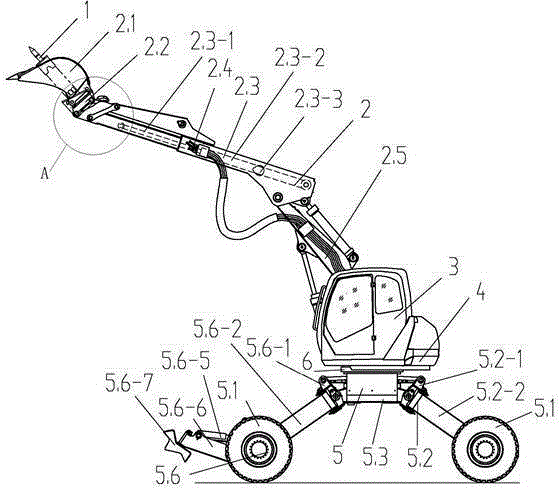
Figure 201410011760

The invention provides a multifunctional all-terrain walking hydraulic excavator, which includes a multifunctional working device, a cab, a slewing platform assembly, a slewing support, a walking chassis and the like. The multifunctional all-terrain walking hydraulic excavator of the present invention can quickly replace various hydraulic equipment such as buckets, grabs, and breakers through the quick-change device, and connect various hydraulic equipment such as hydraulic drilling rigs and hydraulic vibrating shovels through hydraulic quick joints. Self-rescue, traction rescue, etc. are implemented through the hydraulic winch installed at the front end of the walking chassis. The walking chassis can adapt to the terrain by adjusting the swing angle of the front and rear walking legs, and can walk and work on complex terrain such as mountains, swamps, and steep slopes. The excavator has the characteristics of simple structure and convenient operation, which well solves the problem of maneuverability of mechanical equipment under complex terrain.

Figure 201410011760

Description

A kind of multi-functional full landform hydraulic walking excavator
Technical field
The present invention relates to a kind of excavator, particularly a kind of multi-functional full landform hydraulic walking excavator.
Background technology
Under the impact of national policy guiding and technological progress, China's engineering machinery showed swift and violent growth momentum in recent years, and product category, series are also all the more complete, and excavator is exactly one of them important class, had also obtained very fast development preferably.Excavator of a great variety, according to walking manner, can be divided into crawler type, rubber-tyred and walking etc., crawler-mounted excavator is compared with wheeled excavator has good climbing capacity, stability is better, but its travel speed is not high, both chassis all adopt stationary structure in addition, landform adaptive capacity is limited, for some places as with a varied topography in mountain region, marshland etc., but feel simply helpless, cannot travel and operation in these areas, and the function expansibility of most excavator is poor.Existing a kind of walking type excavator Function Extension ability is poor; Only possess two front-wheel steer functions, two trailing wheels do not possess turning function, and its front wheel steering structure is comparatively complicated, poor to the protective of oil cylinder; Four of chassis are hinged different, and production and processing technology is bad; Its fore paw and supporting leg to connect degree of freedom few, landform adaptive capacity and grab ground poor reliability.The hydraulic walking excavator of other types, the landform adaptive capacity of this excavator is still limited, and it adopts common equipment, and walking performance is lower, and Function Extension ability is also poor.
Summary of the invention
In order to overcome the deficiency of existing crawler type and wheeled excavator and walking type excavator, the invention provides a kind of multi-functional full landform hydraulic walking excavator, this excavator has stronger Function Extension ability, rely on legged chassis and the Multifunctional working device of powerful terrain trafficability energy, can enter the complex areas such as mountain region, abrupt slope, marsh, forest land and travel and operation, landform is adaptable.
The technical solution adopted for the present invention to solve the technical problems is:
A kind of multi-functional full landform hydraulic walking excavator, comprise Multifunctional working device 2, driver's cabin 3, revolving dial assembly 4, legged chassis 5, pivoting support 6, it is characterized in that described Multifunctional working device 2 integral body are hingedly mounted on the right front portion of revolving dial assembly 4; Described driver's cabin 3 is fixed on the left side of revolving dial assembly 4; Described revolving dial assembly 4 carrying driver's cabins 3, Multifunctional working device 2, described revolving dial assembly 4 is connected with legged chassis 5 by pivoting support 6.
Further, described Multifunctional working device 2 comprises scraper bowl 2.1, fast replacing device 2.2, telescopic dipper 2.3, the dipper hydraulic jack 2.3-3 that stretches, hydraulic quick coupling 2.4, curved short swing arm 2.5, connecting rod 2.6, rocking bar 2.7, described curved short swing arm 2.5 is driven by single hydraulic jack, telescopic dipper 2.3 comprises telescopic dipper two joint arm 2.3-1, the dipper hydraulic jack 2.3-2 that stretches, telescopic dipper basic arm 2.3-3, wherein the cross section of telescopic dipper two joint arm 2.3-1 and telescopic dipper basic arm 2.3-3 is rectangular configuration, telescopic dipper two joint arm 2.3-1 are socketed in the inside of telescopic dipper basic arm 2.3-3, in telescopic dipper two joint arm 2.3-1 rear ends, be respectively fixed with a nylon slide block in four sides up and down, the front end of telescopic dipper basic arm 2.3-3 up and down four sides is respectively fixed with a nylon slide block, the mode that the tailpiece of the piston rod of the flexible hydraulic jack 2.3-2 of dipper connects by bearing pin is articulated with the inside of telescopic dipper two joint arm 2.3-1, the mode that the cylinder barrel end of the flexible hydraulic jack 2.3-2 of dipper connects by bearing pin is articulated with the inside of telescopic dipper basic arm 2.3-3, the stretching motion of telescopic dipper 2.3 is driven by the hydraulic jack 2.3-2 that stretches, rotatablely moving of telescopic dipper 2.3 driven by a hydraulic jack, in the both sides of telescopic dipper basic arm 2.3-3, be respectively provided with two hydraulic quick couplings 2.4, two hydraulic quick couplings 2.4 of every side are connected to respectively the delivery outlet of three position four-way directional control valve by hydralic hose, input port by three position four-way directional control valve connects and is connected to respectively reducing valve and fuel tank, reducing valve is connected with hydraulic pump source again, described rocking bar 2.7, connecting rod 2.6 is connected with fast replacing device 2.2 by hydraulic jack, and form linkage together with telescopic dipper 2.3, scraper bowl 2.1 is arranged on fast replacing device 2.2.
Further, described fast replacing device 2.2 comprises quick-change frame 2.2-1, quick changing oil cylinder 2.2-2, dead bolt 2.2-3, quick-change frame 2.2-1 is provided with and telescopic dipper two joint arm 2.3-1 the hinge hole 2.2-4 being connected and the hinge hole 2.2-5 that are connected with rocking bar 2.7, be provided with the open type connecting hole 2.2-7 and the hook-type connecting hole 2.2-6 that are connected fast with work tool simultaneously, in the middle of dead bolt 2.2-3 and rear end is respectively equipped with hinge hole 2.2-8 and hinge hole 2.2-9, front end is with arc structure, dead bolt 2.2-3 is connected with quick-change frame 2.2-1 by middle hinge hole 2.2-8, by rear end hinge hole 2.2-9, be connected with the tailpiece of the piston rod of quick changing oil cylinder 2.2-2, hinged being fixed on quick-change frame 2.2-1 of cylinder barrel end of quick changing oil cylinder 2.2-2.
Further, comprise base 5.3, left front walking-leg 5.6, right front walking-leg 5.5, left back walking-leg 5.2, right back walking-leg 5.4, four wheels 5.1, with hydraulic capstan 5.9, described base 5.3 front ends are installed hydraulic capstan 5.9, four jiaos of described base 5.3 are respectively provided with a hinge hole, described left front walking-leg 5.6, right front walking-leg 5.5, left back walking-leg 5.2 and right back walking-leg 5.4 are respectively by left front leg articulated 5.6-1, the hinged 5.5-1 of RAT, the hinged 5.2-1 of left back leg is connected with four hinge holes of base 5.3 with right rear leg articulated 5.4-1, the oscilaltion campaign of above-mentioned each walking-leg is respectively by left front walking-leg lifting hydraulic jack 5.10, left back walking-leg lifting hydraulic jack 5.11, right front walking-leg lifting hydraulic jack 5.8 and right back walking-leg lifting hydraulic jack 5.7 drive.
Further, described left front walking-leg 5.6 and right front walking-leg 5.5 comprise respectively left front leg articulated 5.6-1 and the hinged 5.5-1 of RAT, left front leg joint 5.6-2 and RAT joint 5.5-2, left front leg wheel hub 5.6-3 and right front wheel hub 5.5-3, left front supporting leg 5.6-4 and right front supporting leg 5.5-4, left front pawl 5.6-5 and right front pawl 5.5-5, between each parts of described walking-leg, all adopt articulated manner to be connected, described right front pawl 5.5-5 comprises a longitudinal axis 5.5-5-1, by longitudinal axis 5.5-5-1, be connected in the axle sleeve of right front supporting leg 5.5-4 front end, described right front pawl 5.5-5 is welded by M shape bending plate 5.5-5-2 and three riser 5.5-5-3 that are provided with " M " shape lug tooth, described M shape bending plate 5.5-5-2 front-end and back-end are equipped with the lug tooth of " M " shape, in ramp angles, hour can use the first two tooth of three riser 5.5-5-3 to grab ground, when ramp angles is larger, can use latter two tooth of three riser 5.5-5-3 to grab ground, described left front pawl 5.6-5 is identical with the structure of right front pawl 5.5-5.
Further, described four wheels 5.1 link together with left front leg wheel hub 5.6-3, RAT wheel hub 5.5-3, left back leg wheel hub 5.2-3 and right rear leg wheel hub 5.4-3 respectively by four hydraulic motors.
Further, described left front walking-leg 5.6, right front walking-leg 5.5, left back walking-leg 5.2 and right back walking-leg 5.4 are driven all and can independently or synchronously be swung by hydraulic jack, turning to by wheel steering oil cylinder 5.5-7 of wheel 5.1 drives, and the swing of right front walking-leg 5.5 is driven by left front walking-leg oscillating oil cylinder 5.5-6.
Further, the arrangement of the hinged seat of the left front walking-leg lifting hydraulic jack 5.10 of four the walking-leg oscilaltions of driving on described chassis 5.3, left back walking-leg lifting hydraulic jack 5.11, right front walking-leg lifting hydraulic jack 5.8 and right back walking-leg lifting hydraulic jack 5.7 is for intersecting symmetrical structure.
Front vehicle wheel of the present invention and rear wheel adopt wide base tyre, and grounding pressure is little, by hydraulic motor, is connected respectively with foreleg wheel hub with back leg wheel hub.Described revolving dial assembly is the load bearing component of top driver's cabin, Multifunctional working device and power set etc., by pivoting support, is connected with legged chassis, by hydraulic rotary motor, is driven and can be realized 360 ° of full circle swingings.
The invention has the beneficial effects as follows, the present invention has effectively realized terrain trafficability and the compliance of complete machine, significantly promoted the maneuverability of complete machine in complex job environment, complete machine can possess several functions simultaneously, realize several work, improve job area and operating efficiency, and overall structure is simple, has promoted production and processing efficiency.Be in particular in:
The first, the terrain trafficability when significantly promoting complete machine and travelling.The one, can realize the independent hydraulically controlled motor of four-wheel and drive and travel, can realize two front-wheel steers, two rear-axle steerings, all-wheel steering, front walking-leg synchronous swing turn to, the synchronous swing of rear walking-leg turn to and crab row turning function, turning radius is little; The 2nd, can realize under transport condition and adjust base terrain clearance by adjusting the angle that swings up and down of each walking-leg, reach and avoid the object that roadblock and paddling travels etc.; The 3rd, can realize the width of adjusting legged chassis under transport condition by adjusting the angle that swings of each walking-leg, reach and by narrow road surface, across trench both sides, carry out the objects such as operation; The 4th, can realize in the process of moving, lift a wherein walking-leg, adopt three-wheel to travel, reach the object that single leg is avoided road barrier.
The second, by walking, by the complete machine of the cooperation realization of walking-leg, equipment before and after handling, advance and greatly promote the landform compliance of complete machine.This programme can be realized climbing wide-angle slope, crosses over vertical obstacle, Crossing ditch, the operation such as paddle.
The 3rd, significantly improve slope job stabilization and safety.The one, can realize the independent angle of bobbing and weaving of adjusting each walking-leg, guarantee that revolving dial keeps level or approaches level on the slope, greatly improved operating personnel's operation comfort level, can avoid operation to cause the damage to elements such as pivoting support, motor, rotary reducers simultaneously; The 2nd, can be by realizing with front leg strut supporting ground the stability that non-yielding prop improves operation; The 3rd, by being arranged on the hydraulic capstan of front portion, legged chassis, can realizing tying in operation process and guarantee job safety.
The 4th, the multifunctionality of enhancing complete machine.The one, the lifting hook in described equipment on connecting rod can be used for reliably tying rope or the suspension hook of lifting, avoids tying coming off; The 2nd, the hydraulic quick coupling that is placed in equipment both sides can be embodied as the multiple hydraulic tools such as hydraulic drill rig, hydraulic vibration shovel provides hydraulic power, the function of expansion complete machine; The 3rd, the fast replacing device in described equipment can be realized operating personnel's several work facility such as quick-replaceable scraper bowl, grab bucket, quartering hammer in driver's cabin; Four hydraulic capstans that are mounted in base front end can be realized the functions such as towing vehicle, rescue.
The 5th, the main body on chassis adopts symmetrical structure, on it, the arrangement of the hinged seat of four walking-leg oscilaltion oil cylinders is for intersecting symmetrical structure, like this layout can so that left front leg hinged with the identical structure of the hinged employing of right rear leg, the hinged structure identical with the hinged employing of left back leg of RAT, so just can reduce the kind of structural member, make processing and assembling simpler, promote the efficiency of production and processing.
Accompanying drawing explanation
Below in conjunction with drawings and Examples, the present invention is further described.
Fig. 1 is structural representation of the present invention.
Fig. 2 is that in Fig. 1, A goes out enlarged diagram.
Fig. 3 is fast replacing device schematic diagram.
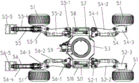
Fig. 4 is legged chassis schematic diagram of the present invention.
Fig. 5 is the schematic diagram of the right front walking-leg of the present invention.
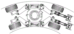
Fig. 6 is the schematic diagram that legged chassis all-wheel steering+front and back walking swing of leg turns to.
Fig. 7 is the schematic diagram of walking climbing of the present invention.
Fig. 8 is that the present invention is across the schematic diagram of trench operation.
Fig. 9 is the schematic diagram of slope of the present invention operation.
In figure: 1 quartering hammer 2 Multifunctional working devices, 2.1 scraper bowl, 2.2 fast replacing device, 2.2-1 quick-change frame, 2.2-2 quick changing oil cylinder, 2.2-3 dead bolt, 2.2-4 connecting hole, 2.2-5 connecting hole, 2.2-6 connecting hole, 2.2-7 connecting hole, 2.2-8 connecting hole, 2.2-9 connecting hole, 2.3 telescopic dippers, the telescopic dipper two joint arms of 2.3-1, 2.3-2 telescopic dipper basic arm, the hydraulic jack 2.3-3 dipper stretches, 2.4 hydraulic power rapid replacing interfaces, 2.5 short curved swing arm, 2.6 connecting rod, 2.6-1 lifting hook, 2.7 rocking bar, 3 driver's cabins, 4 revolving dial assemblies, 5 legged chassis, 5.1 wheel, 5.2 left back walking-legs, 5.2-1 left back leg articulated, the left back leg joint of 5.2-2, 5.2-3 left back leg wheel hub, the left back leg joint of 5.2-2, 5.3 base, 5.4 right back walking-legs, 5.4-1 right rear leg articulated, 5.4-2 right rear leg joint, 5.4-3 right rear leg wheel hub, 5.5 right front walking-legs, 5.5-1 RAT articulated, 5.5-2 RAT joint, 5.5-3 RAT wheel hub, the right front supporting leg of 5.5-4, the right front pawl of 5.5-5, 5.5-5-1 longitudinal axis, 5.5-5-2 bending plate, 5.5-5-3 riser, 5.5-6 wheel steering oil cylinder, 5.5-7 right front walking-leg oscillating oil cylinder, 5.6 left front walking-legs, 5.6-1 left front leg articulated, 5.6-2 left front leg joint, 5.6-3 left front leg wheel hub, the left front supporting leg of 5.6-4, the left front pawl of 5.6-5, 5.7 right back walking-leg lifting hydraulic jacks, 5.8 right front walking-leg lifting hydraulic jacks, 5.9 hydraulic capstan, 5.10 left front walking-leg lifting hydraulic jacks, 5.11 left back walking-leg lifting hydraulic jacks, 6 pivoting supports.
  
The specific embodiment
Below with reference to the accompanying drawings, the specific embodiment of the present invention is described in detail.
As shown in Figure 1, a kind of multi-functional full landform hydraulic walking excavator comprises Multifunctional working device 2, driver's cabin 3, revolving dial assembly 4, legged chassis 5, pivoting support 6.Described Multifunctional working device 2 integral body are hingedly mounted on the right front portion of revolving dial assembly 4; Described driver's cabin 3 is fixed on the left side of revolving dial assembly 4; Described revolving dial assembly 4 is load bearing components of top driver's cabin 3, Multifunctional working device 2 etc., by pivoting support 6, is connected with legged chassis 5.
As shown in Figure 1, described Multifunctional working device 2 adopts " curved short swing arm+telescopic dipper " structure, comprise curved short swing arm 2.5, telescopic dipper 2.3, scraper bowl 2.1, connecting rod 2.6, rocking bar 2.7, fast replacing device 2.2, the flexible hydraulic jack 2.3-3 of dipper, hydraulic quick coupling 2.4, described curved short swing arm 2.5 is driven by single hydraulic jack.Telescopic dipper 2.3 comprises telescopic dipper two joint arm 2.3-1, dipper flexible hydraulic jack 2.3-2, telescopic dipper basic arm 2.3-3.The cross section of telescopic dipper two joint arm 2.3-1 and telescopic dipper basic arm 2.3-3 is rectangular configuration, telescopic dipper two joint arm 2.3-1 are socketed in the inside of telescopic dipper basic arm 2.3-3, in telescopic dipper two joint arm 2.3-1 rear ends, be respectively fixed with a nylon slide block in four sides up and down, the front end of telescopic dipper basic arm 2.3-3 up and down four sides is respectively fixed with a nylon slide block.As shown in Figure 1, the mode that the tailpiece of the piston rod of the flexible hydraulic jack 2.3-2 of dipper connects by bearing pin is articulated with the inside of telescopic dipper two joint arm 2.3-1, and the mode that the cylinder barrel end of the flexible hydraulic jack 2.3-2 of dipper connects by bearing pin is articulated with the inside of telescopic dipper basic arm 2.3-3.The stretching motion of telescopic dipper 2.3 is driven by the hydraulic jack 2.3-2 that stretches, and makes telescopic dipper two joint arm 2.3-1 slide and realize in the inside of telescopic dipper basic arm 2.3-3.Rotatablely moving of telescopic dipper 2.3 driven by a hydraulic jack.In the both sides of telescopic dipper basic arm 2.3-3, be respectively provided with two hydraulic quick couplings 2.4, the quantity of hydraulic quick coupling 2.4 also can increase according to actual needs.Two hydraulic quick couplings 2.4 of every side are connected to respectively the delivery outlet of three position four-way directional control valve by hydralic hose, the input port by three position four-way directional control valve connects and is connected to respectively reducing valve and fuel tank, and reducing valve is connected with hydraulic pump source again.Described rocking bar 2.7, connecting rod 2.6 are connected with fast replacing device 2.2 by hydraulic jack, and form linkage together with telescopic dipper 2.3, and scraper bowl 2.1 is arranged on fast replacing device 2.2.As shown in Fig. 2~3, described fast replacing device 2.2, is comprised of quick-change frame 2.2-1, quick changing oil cylinder 2.2-2, dead bolt 2.2-3.Quick-change frame 2.2-1 is provided with and telescopic dipper two joint arm 2.3-1 the hinge hole 2.2-4 being connected and the hinge hole 2.2-5 that are connected with rocking bar 2.7, be provided with simultaneously with as scraper bowl, open type connecting hole 2.2-7 and hook-type connecting hole 2.2-6 that the work tool of quartering hammer etc. connects fast, in the middle of dead bolt 2.2-3 and rear end is respectively equipped with hinge hole 2.2-8 and hinge hole 2.2-9, front end is with arc structure, dead bolt 2.2-3 is connected with quick-change frame 2.2-1 by middle hinge hole 2.2-8, by rear end hinge hole 2.2-9, be connected with the tailpiece of the piston rod of quick changing oil cylinder 2.2-2, hinged being fixed on quick-change frame 2.2-1 of cylinder barrel end of quick changing oil cylinder 2.2-2.Described fast replacing device 2.2, by a connecting axle of hook-type connecting hole 2.2-6 connection implement, by quick changing oil cylinder 2.2-2, promote dead bolt 2.2-3 again and rotate around middle hinge hole 2.2-8, by dead bolt 2.2-3 front end with arc structure and the connecting hole 2.2-7 of locking rack 2.2-1 coordinate and form 3/4 and justify connecting hole and be connected with another connecting axle of work tool; While disconnecting, only need retraction quick changing oil cylinder 2.2-2, make dead bolt 2.2-3 around middle hinge hole 2.2-8 rotation, make dead bolt 2.2-3 front end with arc structure and the connecting hole opening that forms of the connecting hole 2.2-7 of locking rack 2.2-1 increase, thereby the connecting axle of work tool is spun off from fast replacing device 2.2.The whole Renewal process of work tool only needs operator in driver's cabin, to control quick changing oil cylinder 2.2-2 to realize, simple to operate, change quick.Between described equipment 2 each parts, all adopt and be articulated and connected, by each hydraulic jack flexible, complete various operations and move.Described curved short swing arm 2.5, telescopic dipper 2.3 are box-shaped welded construction, and connecting rod 2.6 is welded-steel plate construction, as shown in Figure 2, is welded with lifting hook 2.6-1 on connecting rod 2.6.Rocking bar 2.7 is single slab, and scraper bowl 2.1 is welded-steel plate construction.
As shown in Figures 4 and 5, described legged chassis 5 is symmetrical formula structure, comprises base 5.3, left front walking-leg 5.6, right front walking-leg 5.5, left back walking-leg 5.2, right back walking-leg 5.4, wheel 5.1 and hydraulic capstan 5.9.Described base 5.3 front ends are provided with hydraulic capstan 5.9, four jiaos of described base 5.3 are respectively provided with a hinge hole, described left front walking-leg 5.6, right front walking-leg 5.5, left back walking-leg 5.2 and right back walking-leg 5.4 are respectively by left front leg articulated 5.6-1, the hinged 5.5-1 of RAT, the hinged 5.2-1 of left back leg is connected with four hinge holes of base 5.3 with right rear leg articulated 5.4-1, the oscilaltion campaign of above-mentioned each walking-leg is respectively by left front walking-leg lifting hydraulic jack 5.10, left back walking-leg lifting hydraulic jack 5.11, right front walking-leg lifting hydraulic jack 5.8 and right back walking-leg lifting hydraulic jack 5.7 drive.Described left front walking-leg 5.6 and right front walking-leg 5.5 are comprised of left front leg articulated 5.6-1 and the hinged 5.5-1 of RAT, left front leg joint 5.6-2 and RAT joint 5.5-2, left front leg wheel hub 5.6-3 and right front wheel hub 5.5-3, left front supporting leg 5.6-4 and right front supporting leg 5.5-4, left front pawl 5.6-5 and right front pawl 5.5-5 etc. respectively, be and adopt articulated manner to be connected between described each parts of each walking-leg.Described right front pawl 5.5-5 comprises a longitudinal axis 5.5-5-1, by longitudinal axis 5.5-5-1, be connected in the axle sleeve of right front supporting leg 5.5-4 front end, described right front pawl 5.5-5 is welded by M shape bending plate 5.5-5-2 and three riser 5.5-5-3 that are provided with " M " shape lug tooth, described M shape bending plate 5.5-5-2 front-end and back-end are equipped with the lug tooth of " M " shape, in ramp angles, hour can use the first two tooth of three riser 5.5-5-3 to grab ground, when ramp angles is larger, can use latter two tooth of three riser 5.5-5-3 to grab ground.Described left front pawl 5.6-5 is identical with the structure of right front pawl 5.5-5.
The structural similarity of described left back walking-leg 5.2 and right back walking-leg 5.4 and right front walking-leg 5.5 and left front walking-leg 5.6, does not just have front leg strut.Described four wheels 5.1 link together with left front leg wheel hub 5.6-3, RAT wheel hub 5.5-3, left back leg wheel hub 5.2-3 and right rear leg wheel hub 5.4-3 respectively by four hydraulic motors.
As shown in Figure 4, described left front walking-leg 5.6, right front walking-leg 5.5, left back walking-leg 5.2 and right back walking-leg 5.4 are driven all and can independently or synchronously be bobbed and woven by hydraulic jack.As shown in Figure 5, wheel steering oil cylinder 5.5-7 and right front walking-leg oscillating oil cylinder 5.5-6 arrange up and down, tailpiece of the piston rod and the RAT wheel hub 5.5-3 of wheel steering oil cylinder 5.5-7 are hinged, cylinder barrel end and the RAT articulated 5.5-1 of wheel steering oil cylinder 5.5-7 are hinged, the tailpiece of the piston rod of right front walking-leg oscillating oil cylinder 5.5-6 and RAT joint 5.5-2 are hinged, and cylinder barrel end and the RAT articulated 5.5-1 of right front walking-leg oscillating oil cylinder 5.5-6 are hinged.Turning to by wheel steering oil cylinder 5.5-7 of wheel 5.1 drives, and the swing of right front walking-leg 5.5 is driven by right front walking-leg oscillating oil cylinder 5.5-6.The wheel steering of described left front walking-leg 5.6, left back walking-leg 5.2 and right back walking-leg 5.4 swings with right front walking-leg 5.5 and adopts identical principle with walking-leg.Therefore, the excavator of this programme has less turning radius, can realize four walking-legs swings and turn to and four wheel steerings, and its schematic diagram as shown in Figure 6.
As shown in Figure 4, the main body on described chassis 5.3 adopts symmetrical structure, on it, drive the left front walking-leg lifting hydraulic jack 5.10 of four walking-leg oscilaltions, left back walking-leg lifting hydraulic jack 5.11, the arrangement of the hinged seat of right front walking-leg lifting hydraulic jack 5.8 and right back walking-leg lifting hydraulic jack 5.7 is for intersecting symmetrical structure, layout can be so that the hinged 5.6-1 of left front leg and the hinged 5.4-1 of right rear leg adopt identical structure like this, the hinged 5.5-1 of RAT and the hinged 5.2-1 of left back leg adopt identical structure, so just can reduce the kind of component, make processing and assembling simpler, promote production and processing efficiency.
As shown in Figure 4, described four wheels 5.1 adopt wide base tyres, and grounding pressure is little, make that complete machine is preferably to travel and operation in places such as marshland, backwoods.
As shown in Figure 7, the implementation method of this programme walking climbing is: excavator travels to slope, without the wheel face of fore paw to ramp, adjust Multifunctional working device 2 towards direction of fall, handle left front walking-leg 5.6, right front walking-leg 5.5 and left back walking-leg 5.2, the oil cylinder of right back walking-leg 5.4 makes each walking-leg abduction to maximum deployed condition, handling telescopic dipper 2.3 is reduced to the shortest, with scraper bowl 2.1, support ground, left front walking-leg 5.6 and right front walking-leg 5.5 are lifted, utilize curved short swing arm 2.5, the flexible strength of telescopic dipper 2.3 promotes excavator and drives two unmatched claw wheels 5.1 when moving on slope, make excavator climbing, when telescopic dipper 2.3 extends range, stop telescopic dipper 2.3 motions and two unmatched claw wheels 5.1 drivings simultaneously, and left front walking-leg 5.6 and right front walking-leg 5.5 are placed to ground, with left front pawl 5.6-5 and right front pawl 5.5-5, supporting excavator makes it after horizontal positioned state, the slow built on stilts of scraper bowl 2.1, so far just completes walking climbing.
The implementation of crossing over vertical obstacle is: excavator is adjusted into two front vehicle wheels 5.1 front, two rear wheels 5.1 are rear, travel near vertical obstacle, handling the flexible hydraulic jack 2.3-3 of dipper makes telescopic dipper 2.3 be reduced to the shortest scraper bowl 2.1 to be supported on obstacle, two front vehicle wheels 5.1 slowly raise, drive two rear wheels 5.1 simultaneously, near obstacle, two front vehicle wheels 5.1 are placed on obstacle and are pressed after stopping brake, rotate revolving dial assembly 4, scraper bowl 2.1 is supported near ground obstacle, two rear wheels 5.1 slowly raise, drive two front vehicle wheels 5.1 forward simultaneously, until can safely two rear wheels 5.1 be placed on obstacle, complete and cross over vertical obstacle.
As shown in Figure 8, the implementation of Crossing ditch operation is: according to the width of trench, operating hydraulically operated oil cylinder is adjusted the outwards angle of swing of left front walking-leg 5.6, right front walking-leg 5.5 and left back walking-leg 5.2, right back walking-leg 5.4, make wheel 5.1 Y-axises apart from increase, then can carry out operation and travel across trench top.
As shown in Figure 1, the implementation of fording operation is: when wheeled, travel while paddling, can be according to the situation of the depth of water, operating hydraulically operated oil cylinder is adjusted the angle of left front walking-leg 5.6, right front walking-leg 5.5 and left back walking-leg 5.2, right back walking-leg 5.4 lower swings, chassis is improved, then can handle to travel and paddle; When walking, travel while paddling, the mode that can apply walking climbing is paddled and is advanced.
As shown in Figure 9, on slope, the implementation of operation is: operating hydraulically operated oil cylinder is adjusted left front walking-leg 5.6, right front walking-leg 5.5 and left back walking-leg 5.2, upper and lower and the angle that swings of right back walking-leg 5.4, can guarantee that revolving dial assembly 4 on the slope keeps level or approaches level, thereby greatly improve operating personnel's operation comfort level, can avoid operation to cause pivoting support simultaneously, motor, the damage of the elements such as rotary reducer, in addition as shown in Figure 7, can realize the stability that non-yielding prop improves operation by the left front pawl 5.6-1 with left front walking-leg 5.6 and right front walking-leg 5.5 and right front pawl 5.5-1 supporting ground.For strengthening at the operational security of tiltedly putting on, can guarantee job safety by being arranged on hydraulic capstan 5.9 the tying in operation process of 5.3 front portions, legged chassis.
The three-wheel implementation of keeping away barrier that travels is: in the process of moving, can raise in left front walking-leg 5.6, right front walking-leg 5.5, left back walking-leg 5.2 and right back walking-leg 5.4 one by operating hydraulically operated oil cylinder and realize and in advancing, keep away barrier and travel.
The foregoing is only preferred embodiment of the present invention, be not limited to the present invention, all within principle of the present invention and principle, any modification of doing, be equal to replacement, improvement etc., within all should being included in protection scope of the present invention.
  

Claims (8)

1. a multi-functional full landform hydraulic walking excavator, comprise Multifunctional working device (2), driver's cabin (3), revolving dial assembly (4), legged chassis (5), pivoting support (6), it is characterized in that described Multifunctional working device (2) integral body is hingedly mounted on the right front portion of revolving dial assembly (4); Described driver's cabin (3) is fixed on the left side of revolving dial assembly (4); Described revolving dial assembly (4) carrying driver's cabin (3), Multifunctional working device (2), described revolving dial assembly (4) is connected with legged chassis (5) by pivoting support (6).
2. multi-functional full landform hydraulic walking excavator as claimed in claim 1, it is characterized in that described Multifunctional working device (2) comprises scraper bowl (2.1), fast replacing device (2.2), telescopic dipper (2.3), the dipper hydraulic jack (2.3-3) that stretches, hydraulic quick coupling (2.4), curved short swing arm (2.5), connecting rod (2.6), rocking bar (2.7), described curved short swing arm (2.5) is driven by single hydraulic jack, telescopic dipper (2.3) comprises telescopic dipper two joint arms (2.3-1), the dipper hydraulic jack (2.3-2) that stretches, telescopic dipper basic arm (2.3-3), wherein the cross section of telescopic dipper two joint arms (2.3-1) and telescopic dipper basic arm (2.3-3) is rectangular configuration, telescopic dipper two joint arms (2.3-1) are socketed in the inside of telescopic dipper basic arm (2.3-3), in telescopic dipper two joint arm (2.3-1) rear ends, be respectively fixed with a nylon slide block in four sides up and down, the front end of telescopic dipper basic arm (2.3-3) up and down four sides is respectively fixed with a nylon slide block, stretch mode that the tailpiece of the piston rod of hydraulic jack (2.3-2) connects by bearing pin of dipper is articulated with the inside of telescopic dipper two joint arms (2.3-1), stretch mode that the cylinder barrel end of hydraulic jack (2.3-2) connects by bearing pin of dipper is articulated with the inside of telescopic dipper basic arm (2.3-3), the stretching motion of telescopic dipper (2.3) is driven by the hydraulic jack that stretches (2.3-2), rotatablely moving of telescopic dipper (2.3) driven by a hydraulic jack, in the both sides of telescopic dipper basic arm (2.3-3), be respectively provided with two hydraulic quick couplings (2.4), two hydraulic quick couplings (2.4) of every side are connected to respectively the delivery outlet of three position four-way directional control valve by hydralic hose, input port by three position four-way directional control valve connects and is connected to respectively reducing valve and fuel tank, reducing valve is connected with hydraulic pump source again, described rocking bar (2.7), connecting rod (2.6) is connected with fast replacing device (2.2) by hydraulic jack, and form linkage together with telescopic dipper (2.3), scraper bowl (2.1) is arranged on fast replacing device (2.2).
3. multi-functional full landform hydraulic walking excavator as claimed in claim 2, it is characterized in that described fast replacing device (2.2) comprises quick-change frame (2.2-1), quick changing oil cylinder (2.2-2), dead bolt (2.2-3), quick-change frame (2.2-1) is provided with and telescopic dipper two joint arm (2.3-1) hinge hole (2.2-4) being connected and the hinge holes (2.2-5) that are connected with rocking bar (2.7), be provided with the open type connecting hole (2.2-7) and the hook-type connecting hole (2.2-6) that are connected fast with work tool simultaneously, in the middle of dead bolt (2.2-3) and rear end is respectively equipped with hinge hole (2.2-8) and hinge hole (2.2-9), front end is with arc structure, dead bolt (2.2-3) is connected with quick-change frame (2.2-1) by middle hinge hole (2.2-8), by rear end hinge hole (2.2-9), be connected with the tailpiece of the piston rod of quick changing oil cylinder (2.2-2), hinged being fixed on quick-change frame (2.2-1) of cylinder barrel end of quick changing oil cylinder (2.2-2).
4. multi-functional full landform hydraulic walking excavator as claimed in claim 1, is characterized in that comprising base (5.3), left front walking-leg (5.6), right front walking-leg (5.5), left back walking-leg (5.2), right back walking-leg (5.4), four wheels (5.1), and hydraulic capstan (5.9), (5.3 front ends are installed hydraulic capstan (5.9) to described base, and four jiaos of described base (5.3) are respectively provided with a horizontally hinged hole, described left front walking-leg (5.6), right front walking-leg (5.5), left back walking-leg (5.2) and right back walking-leg (5.4) are respectively by left front leg articulated (5.6-1), RAT hinged (5.5-1), left back leg hinged (5.2-1) is connected with four hinge holes of base (5.3) with right rear leg articulated (5.4-1), and the oscilaltion campaign of above-mentioned each walking-leg is respectively by left front walking-leg lifting hydraulic jack (5.10), left back walking-leg lifting hydraulic jack (5.11), right front walking-leg lifting hydraulic jack (5.8) and right back walking-leg lifting hydraulic jack (5.7) drive.
5. multi-functional full landform hydraulic walking excavator as claimed in claim 4, it is characterized in that described left front walking-leg (5.6) and right front walking-leg (5.5) comprise respectively left front leg articulated (5.6-1) and RAT hinged (5.5-1), left front leg joint (5.6-2) and RAT joint (5.5-2), left front leg wheel hub (5.6-3) and right front wheel hub (5.5-3), left front supporting leg (5.6-4 and right front supporting leg (5.5-4), left front pawl (5.6-5) and right front pawl (5.5-5), between each parts of described walking-leg, all adopt articulated manner to be connected, described right front pawl (5.5-5) comprises a longitudinal axis (5.5-5-1), by longitudinal axis (5.5-5-1), be connected in the axle sleeve of right front supporting leg (5.5-4) front end, described right front pawl (5.5-5) is welded by M shape bending plate (5.5-5-2) and three risers (5.5-5-3) that are provided with " M " shape lug tooth, described M shape bending plate (5.5-5-2) front-end and back-end are equipped with the lug tooth of " M " shape, in ramp angles, hour can use the first two tooth of three risers (5.5-5-3) to grab ground, when ramp angles is larger, can use latter two tooth of three risers (5.5-5-3) to grab ground, described left front pawl (5.6-5) is identical with the structure of right front pawl (5.5-5).
6. multi-functional full landform hydraulic walking excavator as claimed in claim 5, is characterized in that described four wheels (5.1) link together with left front leg wheel hub (5.6-3), RAT wheel hub (5.5-3), left back leg wheel hub (5.2-3) and right rear leg wheel hub (5.4-3) respectively by four hydraulic motors.
7. multi-functional full landform hydraulic walking excavator as claimed in claim 6, it is characterized in that described left front walking-leg (5.6), right front walking-leg (5.5), left back walking-leg (5.2) and right back walking-leg (5.4) are driven all and can independently or synchronously be swung by hydraulic jack, turning to by wheel steering oil cylinder (5.5-7) of wheel (5.1) drives, and the swing of right front walking-leg (5.5) is driven by left front walking-leg oscillating oil cylinder (5.5-6).
8. multi-functional full landform hydraulic walking excavator as claimed in claim 7, is characterized in that the arrangement of hinged seat of left front walking-leg lifting hydraulic jack (5.10), left back walking-leg lifting hydraulic jack (5.11), right front walking-leg lifting hydraulic jack (5.8) and right back walking-leg lifting hydraulic jack (5.7) of four the walking-leg oscilaltions of driving on described chassis (5.3) is for intersecting symmetrical structure.
CN201410011760.2A 2014-01-10 2014-01-10 A kind of multi-functional full landform hydraulic walking excavator Active CN103726518B (en)

Priority Applications (4)

Application Number Priority Date Filing Date Title
CN201410011760.2A CN103726518B (en) 2014-01-10 2014-01-10 A kind of multi-functional full landform hydraulic walking excavator
PCT/CN2015/070317 WO2015103985A1 (en) 2014-01-10 2015-01-08 Multifunctional all-terrain walking hydraulic excavator
US15/206,883 US20160319513A1 (en) 2014-01-10 2016-07-11 Multifunctional all-terrain walking hydraulic excavator
ZA2016/04850A ZA201604850B (en) 2014-01-10 2016-07-13 Multifunctional all-terrain walking hydraulic excavator

Applications Claiming Priority (1)

Application Number Priority Date Filing Date Title
CN201410011760.2A CN103726518B (en) 2014-01-10 2014-01-10 A kind of multi-functional full landform hydraulic walking excavator

Publications (2)

Publication Number Publication Date
CN103726518A true CN103726518A (en) 2014-04-16
CN103726518B CN103726518B (en) 2015-11-04

Family

ID=50450789

Family Applications (1)

Application Number Title Priority Date Filing Date
CN201410011760.2A Active CN103726518B (en) 2014-01-10 2014-01-10 A kind of multi-functional full landform hydraulic walking excavator

Country Status (4)

Country Link
US (1) US20160319513A1 (en)
CN (1) CN103726518B (en)
WO (1) WO2015103985A1 (en)
ZA (1) ZA201604850B (en)

Cited By (36)

* Cited by examiner, † Cited by third party
Publication number Priority date Publication date Assignee Title
CN104084943A (en) * 2014-06-26 2014-10-08 西南科技大学 Hydraulically-controlled demolition robot in intense-radiation environment
CN104213592A (en) * 2014-09-18 2014-12-17 四川戴克机械设备有限公司 Crushing and excavation integral type backhoe loader
CN104647357A (en) * 2015-01-09 2015-05-27 广西大学 Four-degree-of-freedom stepper motor driving joint-type manipulator
WO2015103985A1 (en) * 2014-01-10 2015-07-16 徐工集团工程机械股份有限公司道路机械分公司 Multifunctional all-terrain walking hydraulic excavator
CN104831765A (en) * 2015-05-28 2015-08-12 南宁远卓新能源科技有限公司 Excavator with arc arm
CN105442652A (en) * 2016-01-07 2016-03-30 厦门理工学院 Multi-working-arm engineering van
CN105464165A (en) * 2016-01-08 2016-04-06 福建海山机械股份有限公司 Excavator chassis with folding supporting legs
CN105625492A (en) * 2016-01-07 2016-06-01 厦门理工学院 Safe engineering truck
CN105644648A (en) * 2016-01-07 2016-06-08 厦门理工学院 Multi-degree-of-freedom deformable chassis
WO2017027986A1 (en) * 2015-08-19 2017-02-23 杨一男 Walking excavator
CN106836359A (en) * 2017-03-27 2017-06-13 徐工集团工程机械股份有限公司 A kind of walking type excavator and its walking movement system
CN106854884A (en) * 2017-01-31 2017-06-16 遂宁市长丰机械科技有限公司 The hydraulic shear being changed without in excavator arm
CN107792218A (en) * 2017-11-30 2018-03-13 三峡大学 It may span across the engineering vehicle walking device of obstacle
CN108517917A (en) * 2018-07-03 2018-09-11 马鞍山松鹤信息科技有限公司 A kind of walking type excavator
CN108590524A (en) * 2018-06-06 2018-09-28 湖南鼎元机械有限公司 Crawler-type mountain area drilling machine
CN108894265A (en) * 2018-07-26 2018-11-27 徐工集团工程机械有限公司 A kind of equipment fast replacing device of Multifunctional rescue vehicle
CN109188531A (en) * 2018-10-12 2019-01-11 华北水利水电大学 A kind of Electromagnetic Survey of Underground Pipelines device suitable for outdoor complex environment
CN109334769A (en) * 2018-11-22 2019-02-15 徐工消防安全装备有限公司 The chassis of self-propelled aloft working platform and self-propelled aloft working platform
CN109607395A (en) * 2018-12-12 2019-04-12 航天重型工程装备有限公司 A kind of mechanical arm
CN110387802A (en) * 2019-08-05 2019-10-29 上海道基环保科技有限公司 A kind of road cement road surface live breaking method and road breaker entirely
CN110758563A (en) * 2019-10-28 2020-02-07 中船华南船舶机械广州有限公司 Chassis of omnidirectional multifunctional intelligent emergency rescue vehicle
CN110847818A (en) * 2019-12-27 2020-02-28 江西东锐机械有限公司 Walking drilling machine
CN111021458A (en) * 2019-12-04 2020-04-17 徐工集团工程机械有限公司 Intelligent control system and method for arm support type emergency rescue vehicle
CN111764898A (en) * 2020-07-07 2020-10-13 江西金石宝矿山机械制造有限公司 Multifunctional mining machinery stone digging arm
CN111994847A (en) * 2020-09-18 2020-11-27 徐工集团工程机械股份有限公司道路机械分公司 Crawler-type orchard work platform
CN113431113A (en) * 2021-06-25 2021-09-24 江苏国润机械制造有限公司 Connecting structure of excavator bucket and excavator
CN113602380A (en) * 2021-09-01 2021-11-05 江苏徐工工程机械研究院有限公司 Walking chassis for construction machinery and construction machinery
CN113818808A (en) * 2021-10-21 2021-12-21 江西东锐机械有限公司 Bionic drilling rig chassis assembly
CN114208430A (en) * 2021-11-19 2022-03-22 太原科技大学 Agricultural all-terrain walking type deformable chassis device and uphill and downhill method
CN114411860A (en) * 2022-02-10 2022-04-29 江苏徐工工程机械研究院有限公司 Assembly type base of modular walking excavator
CN114687392A (en) * 2022-03-04 2022-07-01 国网江西省电力有限公司电力科学研究院 Crawler type drilling, digging and grabbing multifunctional integrated device and upright rod operation method
CN114775720A (en) * 2022-04-24 2022-07-22 江苏徐工工程机械研究院有限公司 Emergency rescue vehicle and installation method thereof
CN115465025A (en) * 2022-09-16 2022-12-13 西安理工大学 Wheel-shoe-leg amphibious mobile rescue robot
CN116641430A (en) * 2023-05-31 2023-08-25 徐州徐工挖掘机械有限公司 Quick connecting device and engineering machinery
CN118029468A (en) * 2024-03-04 2024-05-14 徐工集团工程机械股份有限公司 A wheel-type rotary drilling rig
CN120465530A (en) * 2025-07-17 2025-08-12 河南大美建筑设计有限公司 A dynamic excavation device and method suitable for road and bridge foundation construction

Families Citing this family (23)

* Cited by examiner, † Cited by third party
Publication number Priority date Publication date Assignee Title
CN105384116A (en) * 2015-12-12 2016-03-09 陕西中汽专用汽车有限公司 Small multifunctional engineering vehicle used for oil field
ITUB20160323A1 (en) * 2016-02-02 2017-08-02 Hymach S R L REMOTE CONTROLLED VEHICLE FOR AGRICULTURAL, FOREST AND ROAD MAINTENANCE
CN106541988A (en) * 2016-11-08 2017-03-29 柳州柳工挖掘机有限公司 Wheel excavator
EP3577281B1 (en) * 2017-01-31 2024-04-10 Volvo Construction Equipment AB Pipe layer attachment for an excavator
US10260214B2 (en) * 2017-05-04 2019-04-16 Caterpillar Inc. Slewing assist system
CN109895979B (en) * 2019-04-12 2023-10-20 罗高生 Magnetic adsorption robot chassis structure of underwater self-adaptive outer circular tube
US11241982B2 (en) * 2019-06-28 2022-02-08 Honda Motor Co., Ltd. Walking infant seat
CN110816491A (en) * 2019-11-07 2020-02-21 山西航天清华装备有限责任公司 Large-scale frame transshipment platform
CN110641570B (en) * 2019-11-07 2024-09-03 武汉轻工大学 Pneumatic bionic wall climbing walking device capable of crossing inner wall
NL2024981B1 (en) * 2020-02-24 2021-10-14 Hudson I P B V Electric drive of mobile apparatus
CN111218960A (en) * 2020-04-09 2020-06-02 宜宾钢猫科技有限公司 Cement silo bottom cleaning robot and cleaning method
CN112919332A (en) * 2021-01-22 2021-06-08 廊坊市融通石油机械设备有限公司 All-terrain multifunctional pipe hoist based on excavator platform
AT17140U3 (en) * 2021-02-23 2021-11-15 Kaiser Ag Walking excavator
CN112896113B (en) * 2021-03-26 2025-04-15 山河智能特种装备有限公司 A kind of outrigger of modular rescue equipment and rescue equipment using the outrigger
CN113374004B (en) * 2021-05-28 2023-03-10 上海交通大学 Unmanned underwater self-propelled winch suction device
CN114148463B (en) * 2021-10-26 2024-06-21 周宏勤 Construction technology of semi-submersible offshore installation platform
CN114592558B (en) * 2022-02-23 2023-05-12 青岛中鸿重型机械有限公司 Transmission system and device of underground battery scraper
CN115263338A (en) * 2022-07-20 2022-11-01 山东科技大学 Development machine auxiliary propulsion mechanism based on 5G technology
CN115787771B (en) * 2022-11-22 2025-11-11 江苏徐工工程机械研究院有限公司 Turntable assembly and engineering mechanical equipment
CN117552710B (en) * 2023-11-07 2024-12-20 国网福建省电力有限公司泉州供电公司 Mountain area wheel step pile hole machine
USD1122994S1 (en) * 2023-11-30 2026-04-21 J. C. Bamford Excavators Limited Part of an excavator arm
CN117944019B (en) * 2024-03-13 2025-12-16 国网北京市电力公司 A operation manipulator for electric wire netting fortune maintenance
CN120552994B (en) * 2025-06-16 2025-11-28 长沙理工大学 A multi-gait clawed spider robot and its motion control method

Citations (2)

* Cited by examiner, † Cited by third party
Publication number Priority date Publication date Assignee Title
CN201180274Y (en) * 2008-02-29 2009-01-14 田永昌 Walking All Terrain Excavator
US7814689B2 (en) * 2006-04-20 2010-10-19 Caterpillar Inc Quick coupler

Family Cites Families (6)

* Cited by examiner, † Cited by third party
Publication number Priority date Publication date Assignee Title
US3688930A (en) * 1971-04-05 1972-09-05 John F Shumaker Extensible dipper stick for backhoe
US4264265A (en) * 1979-05-25 1981-04-28 J. I. Case Company Adjusting slide mechanism for telescoping boom
JP2004203553A (en) * 2002-12-25 2004-07-22 Hitachi Constr Mach Co Ltd Mobile type working machine
CN200940273Y (en) * 2006-07-19 2007-08-29 山东临工工程机械有限公司 Quick exchanging device of working machinery of miniature hydraulic excavator or loader-digger
CN102381642B (en) * 2011-11-29 2013-04-24 徐州天地重型机械制造有限公司 Synchronous telescopic device
CN103726518B (en) * 2014-01-10 2015-11-04 徐工集团工程机械股份有限公司道路机械分公司 A kind of multi-functional full landform hydraulic walking excavator

Patent Citations (2)

* Cited by examiner, † Cited by third party
Publication number Priority date Publication date Assignee Title
US7814689B2 (en) * 2006-04-20 2010-10-19 Caterpillar Inc Quick coupler
CN201180274Y (en) * 2008-02-29 2009-01-14 田永昌 Walking All Terrain Excavator

Cited By (49)

* Cited by examiner, † Cited by third party
Publication number Priority date Publication date Assignee Title
WO2015103985A1 (en) * 2014-01-10 2015-07-16 徐工集团工程机械股份有限公司道路机械分公司 Multifunctional all-terrain walking hydraulic excavator
CN104084943A (en) * 2014-06-26 2014-10-08 西南科技大学 Hydraulically-controlled demolition robot in intense-radiation environment
CN104213592A (en) * 2014-09-18 2014-12-17 四川戴克机械设备有限公司 Crushing and excavation integral type backhoe loader
CN104647357A (en) * 2015-01-09 2015-05-27 广西大学 Four-degree-of-freedom stepper motor driving joint-type manipulator
CN104831765A (en) * 2015-05-28 2015-08-12 南宁远卓新能源科技有限公司 Excavator with arc arm
CN104831765B (en) * 2015-05-28 2017-07-28 南宁远卓新能源科技有限公司 A kind of excavator with arc arm
WO2017027986A1 (en) * 2015-08-19 2017-02-23 杨一男 Walking excavator
CN105442652A (en) * 2016-01-07 2016-03-30 厦门理工学院 Multi-working-arm engineering van
CN105644648B (en) * 2016-01-07 2018-07-31 厦门理工学院 A kind of deformable chassis of multiple degrees of freedom
CN105625492A (en) * 2016-01-07 2016-06-01 厦门理工学院 Safe engineering truck
CN105644648A (en) * 2016-01-07 2016-06-08 厦门理工学院 Multi-degree-of-freedom deformable chassis
CN105442652B (en) * 2016-01-07 2019-01-22 厦门理工学院 An engineering vehicle with multiple working arms
CN105625492B (en) * 2016-01-07 2019-01-22 厦门理工学院 A kind of safety-type engineering truck
CN105464165A (en) * 2016-01-08 2016-04-06 福建海山机械股份有限公司 Excavator chassis with folding supporting legs
CN106854884A (en) * 2017-01-31 2017-06-16 遂宁市长丰机械科技有限公司 The hydraulic shear being changed without in excavator arm
CN106836359A (en) * 2017-03-27 2017-06-13 徐工集团工程机械股份有限公司 A kind of walking type excavator and its walking movement system
CN107792218A (en) * 2017-11-30 2018-03-13 三峡大学 It may span across the engineering vehicle walking device of obstacle
CN107792218B (en) * 2017-11-30 2024-05-28 三峡大学 Engineering vehicle walking device capable of crossing obstacles
CN108590524A (en) * 2018-06-06 2018-09-28 湖南鼎元机械有限公司 Crawler-type mountain area drilling machine
CN108517917A (en) * 2018-07-03 2018-09-11 马鞍山松鹤信息科技有限公司 A kind of walking type excavator
CN108894265A (en) * 2018-07-26 2018-11-27 徐工集团工程机械有限公司 A kind of equipment fast replacing device of Multifunctional rescue vehicle
CN108894265B (en) * 2018-07-26 2023-08-01 江苏徐工工程机械研究院有限公司 Quick-change device for multifunctional rescue vehicle
CN109188531A (en) * 2018-10-12 2019-01-11 华北水利水电大学 A kind of Electromagnetic Survey of Underground Pipelines device suitable for outdoor complex environment
CN109334769A (en) * 2018-11-22 2019-02-15 徐工消防安全装备有限公司 The chassis of self-propelled aloft working platform and self-propelled aloft working platform
CN109607395A (en) * 2018-12-12 2019-04-12 航天重型工程装备有限公司 A kind of mechanical arm
CN110387802A (en) * 2019-08-05 2019-10-29 上海道基环保科技有限公司 A kind of road cement road surface live breaking method and road breaker entirely
CN110387802B (en) * 2019-08-05 2021-09-10 上海道基环保科技有限公司 On-site full-crushing method for road cement pavement and pavement crusher
CN110758563A (en) * 2019-10-28 2020-02-07 中船华南船舶机械广州有限公司 Chassis of omnidirectional multifunctional intelligent emergency rescue vehicle
CN111021458B (en) * 2019-12-04 2022-03-15 徐工集团工程机械有限公司 Intelligent control system and method for arm support type emergency rescue vehicle
CN111021458A (en) * 2019-12-04 2020-04-17 徐工集团工程机械有限公司 Intelligent control system and method for arm support type emergency rescue vehicle
CN110847818A (en) * 2019-12-27 2020-02-28 江西东锐机械有限公司 Walking drilling machine
CN111764898A (en) * 2020-07-07 2020-10-13 江西金石宝矿山机械制造有限公司 Multifunctional mining machinery stone digging arm
CN111994847A (en) * 2020-09-18 2020-11-27 徐工集团工程机械股份有限公司道路机械分公司 Crawler-type orchard work platform
CN111994847B (en) * 2020-09-18 2022-03-29 徐工集团工程机械股份有限公司道路机械分公司 A crawler-type orchard operating platform
CN113431113A (en) * 2021-06-25 2021-09-24 江苏国润机械制造有限公司 Connecting structure of excavator bucket and excavator
CN113431113B (en) * 2021-06-25 2022-07-29 江苏国润机械制造有限公司 Connecting structure of excavator bucket and excavator
CN113602380A (en) * 2021-09-01 2021-11-05 江苏徐工工程机械研究院有限公司 Walking chassis for construction machinery and construction machinery
CN113818808A (en) * 2021-10-21 2021-12-21 江西东锐机械有限公司 Bionic drilling rig chassis assembly
CN114208430A (en) * 2021-11-19 2022-03-22 太原科技大学 Agricultural all-terrain walking type deformable chassis device and uphill and downhill method
CN114411860A (en) * 2022-02-10 2022-04-29 江苏徐工工程机械研究院有限公司 Assembly type base of modular walking excavator
CN114687392A (en) * 2022-03-04 2022-07-01 国网江西省电力有限公司电力科学研究院 Crawler type drilling, digging and grabbing multifunctional integrated device and upright rod operation method
CN114775720A (en) * 2022-04-24 2022-07-22 江苏徐工工程机械研究院有限公司 Emergency rescue vehicle and installation method thereof
CN115465025A (en) * 2022-09-16 2022-12-13 西安理工大学 Wheel-shoe-leg amphibious mobile rescue robot
CN115465025B (en) * 2022-09-16 2024-11-22 西安理工大学 Wheel-shoe-leg amphibious mobile rescue robot
CN116641430A (en) * 2023-05-31 2023-08-25 徐州徐工挖掘机械有限公司 Quick connecting device and engineering machinery
CN116641430B (en) * 2023-05-31 2025-07-25 徐州徐工挖掘机械有限公司 Quick connecting device and engineering machinery
CN118029468A (en) * 2024-03-04 2024-05-14 徐工集团工程机械股份有限公司 A wheel-type rotary drilling rig
CN120465530A (en) * 2025-07-17 2025-08-12 河南大美建筑设计有限公司 A dynamic excavation device and method suitable for road and bridge foundation construction
CN120465530B (en) * 2025-07-17 2025-12-26 河南大美建筑设计有限公司 A dynamic excavation device and method suitable for road and bridge foundation construction

Also Published As

Publication number Publication date
CN103726518B (en) 2015-11-04
WO2015103985A1 (en) 2015-07-16
ZA201604850B (en) 2017-06-28
US20160319513A1 (en) 2016-11-03

Similar Documents

Publication Publication Date Title
CN103726518B (en) A kind of multi-functional full landform hydraulic walking excavator
US9828049B2 (en) Working machine
CN201288503Y (en) Multifunctional drill
JP2656146B2 (en) Moving vehicle
CN205954723U (en) Walking excavator
CN105569104A (en) Working machine
KR102657223B1 (en) An undercarriage for a working machine
CN105569102A (en) Working machine
CN105569106A (en) Working machine
CN102124165A (en) Mobile device
CN105569107A (en) Working machine
KR20210002211A (en) Caterpillar excavator
CN105564236A (en) Chassis of working machine
CN203878633U (en) Novel walking pedrail type double-arm hydraulic excavator
CN118029468A (en) A wheel-type rotary drilling rig
CN203531031U (en) Wheel type maneuvering obstacle breaking vehicle
CN204456247U (en) A kind of multifunction caterpillar excavator
KR20190006273A (en) Agricultural skid steer loader
CN104805878B (en) A kind of self-propelling device with barrier clearing device
CN101117202A (en) Novel hydraulic crawler crane
CN206086482U (en) Crawler -type weight carrier
JPH11222071A (en) Multifunctional work machine
CN109944614A (en) A fully hydraulic self-propelled vertical arch trolley
CN204038913U (en) The dual-purpose machine of traxcavator hoisting crane
CN111605467A (en) Take salvage car of excavation function

Legal Events

Date Code Title Description
C06 Publication
PB01 Publication
C10 Entry into substantive examination
SE01 Entry into force of request for substantive examination
C53 Correction of patent of invention or patent application
CB03 Change of inventor or designer information

Inventor after: Chen Xiufeng

Inventor after: Zhang Jie

Inventor after: Zhang Liping

Inventor after: Wang Fude

Inventor after: Liu Lei

Inventor after: Liu Yuxiang

Inventor after: Wei Yuming

Inventor after: Zhu Kai

Inventor after: Wei Xuefeng

Inventor after: Peng Zhihan

Inventor after: Ding Lianfeng

Inventor after: Shi Xiaoming

Inventor after: Han Jing

Inventor after: Liu Jing

Inventor after: Xue Feng

Inventor after: Xu Jingke

Inventor after: Zhang Yun

Inventor after: Gu Chengpeng

Inventor after: Wu Junqi

Inventor after: Cao Yong

Inventor after: Gao Ran

Inventor before: Chen Xiufeng

Inventor before: Zhang Liping

Inventor before: Wang Fude

Inventor before: Liu Lei

Inventor before: Liu Yuxiang

Inventor before: Wei Yuming

Inventor before: Zhu Kai

Inventor before: Wei Xuefeng

Inventor before: Peng Zhihan

Inventor before: Ding Lianfeng

Inventor before: Han Jing

Inventor before: Shi Xiaoming

Inventor before: Liu Jing

Inventor before: Xue Feng

Inventor before: Xu Jingke

Inventor before: Zhang Yun

Inventor before: Wu Junqi

Inventor before: Cao Yong

Inventor before: Gao Ran

Inventor before: Zhang Jie

COR Change of bibliographic data

Free format text: CORRECT: INVENTOR; FROM: CHEN XIUFENG SHI XIAOMING XUE FENG XU JINGKE ZHANG YUN WU JUNQI CAO YONG GAO RAN ZHANG JIE ZHANG LIPING WANG FUDE LIU LEI LIU YUXIANG WEI YUMING ZHU KAI WEI XUEFENG PENG ZHIHAN DING LIANFENG HAN JING LIU JING TO: CHEN XIUFENG SHI XIAOMING XUE FENG XU JINGKE ZHANG YUN GU CHENGPENG WU JUNQI CAO YONG GAO RAN ZHANG JIE ZHANG LIPING WANG FUDE LIU LEI LIU YUXIANG WEI YUMING ZHU KAI WEI XUEFENG PENG ZHIHAN DING LIANFENG HAN JING LIU JING

C14 Grant of patent or utility model
GR01 Patent grant