CN103722078A - Pre-turning shaping top-concave male die assembly - Google Patents

Pre-turning shaping top-concave male die assembly Download PDF

Info

Publication number
CN103722078A
CN103722078A CN201310707929.3A CN201310707929A CN103722078A CN 103722078 A CN103722078 A CN 103722078A CN 201310707929 A CN201310707929 A CN 201310707929A CN 103722078 A CN103722078 A CN 103722078A
Authority
CN
China
Prior art keywords
punch
turning
male die
advance
formula
Prior art date
Legal status (The legal status is an assumption and is not a legal conclusion. Google has not performed a legal analysis and makes no representation as to the accuracy of the status listed.)
Granted
Application number
CN201310707929.3A
Other languages
Chinese (zh)
Other versions
CN103722078B (en
Inventor
郑东亮
张勇
陈会会
李建文
石炳欣
王胜昌
王卫卫
张文晓
王磊
焦海涛
李少军
张戈
吴雪
Current Assignee (The listed assignees may be inaccurate. Google has not performed a legal analysis and makes no representation or warranty as to the accuracy of the list.)
HEBI TIANQI MOTOR DIES CO Ltd
Original Assignee
HEBI TIANQI MOTOR DIES CO Ltd
Priority date (The priority date is an assumption and is not a legal conclusion. Google has not performed a legal analysis and makes no representation as to the accuracy of the date listed.)
Filing date
Publication date
Application filed by HEBI TIANQI MOTOR DIES CO Ltd filed Critical HEBI TIANQI MOTOR DIES CO Ltd
Priority to CN201310707929.3A priority Critical patent/CN103722078B/en
Publication of CN103722078A publication Critical patent/CN103722078A/en
Application granted granted Critical
Publication of CN103722078B publication Critical patent/CN103722078B/en
Active legal-status Critical Current
Anticipated expiration legal-status Critical

Links

Images

Landscapes

  • Perforating, Stamping-Out Or Severing By Means Other Than Cutting (AREA)

Abstract

The invention discloses a pre-turning shaping top-concave male die assembly comprising a punch male die, a pre-turning male die, a pressure source sleeve, a limit plate and a fixed seat. The punch male die is fixedly connected to the fixed seat, the pressure source sleeve sleeves the lower end outside the punch male die, the pre-turning male die sleeves outside the punch male die and is arranged on the upper portion of the pressure source sleeve, the top of the punch male die is lower than the top of the pre-turning male die, the pre-turning male die is fixedly connected with the punch male die, and the diameter of the lower portion of the pre-turning male die is larger than the diameter of the upper portion; one end of the limit plate is provided with a round hole matching with the upper portion of the pre-turning male die in diameter, one end of the limit plate sleeves outside the pre-turning male die, and the other end is fixedly connected to the fixed seat. Since the pit of the punch male die is formed inside the pre-turning male die, so that the pre-turning male die contact with a workpiece first, flanging is performed before punching, so that unnecessary wear of the punch and wear of a female die sleeve can be avoided, and service lives of the punch and female die sleeve can be prolonged.

Description

Turn in advance shaping top nest punch assemblies
Technical field
The invention belongs to machine casting and processing technique field, be specifically related to one and turn in advance shaping top nest punch assemblies.
Background technology
First punching flange again during product punching, but because drift cutting edge contacts with product in advance, and be local contact, cause repeatedly serious wear after stamping-out, after drift damages, can directly affect the life-span of die case, accelerate die case and damage, after punching, product is jagged, drift is easy to wear, and die case is easy to wear.
Summary of the invention
Technical problem to be solved by this invention is to provide one and turns in advance shaping top nest punch assemblies, the punching again of first flange, thus can avoid the unnecessary wearing and tearing of drift and die case wearing and tearing.
For solving the problems of the technologies described above, the present invention by the following technical solutions:
One is turned over shaping top nest punch assemblies in advance, comprise piercing punch, turn in advance formula punch, pressure source cover, limiting plate and holder, piercing punch is fixedly connected on holder, pressure source cover is nested with in the outside lower end of piercing punch, turning in advance formula punch is nested with in piercing punch outside, and be placed in pressure source cover top, the top of piercing punch is lower than the top of turning in advance formula punch, turning in advance formula punch is fixedly connected with piercing punch, turn in advance section diameter under formula punch and be greater than section diameter, limiting plate one end be provided with turn in advance formula punch on the circular hole that matches of section diameter, limiting plate one end is nested with is turning over formula punch outside in advance, the other end is fixedly connected on holder.
Described piercing punch epimere is provided with at least two keyways, described turning in advance on formula punch, is provided with corresponding screw, turns in advance formula punch and is screwed and is connected with piercing punch.
Described pressure source cover is polyurethane sleeve or silica gel spring.
Described limiting plate is Z-type limiting plate.
Described holder bottom is provided with holder backing plate.
Beneficial effect of the present invention: adopt the shaping top nest punch assemblies of turning in advance of the present invention, because caving in to be placed in, piercing punch turns in advance formula punch inside, making to turn in advance formula punch first contacts with product, the punching again of first flange, thereby avoid the unnecessary wearing and tearing of drift and die case wearing and tearing, improve drift life-span and die case life-span, reduce mold repair time and expense; Eliminate product cracking, Burr Problem, and then improve product and turn over and rush quality, improve part accuracy.
Accompanying drawing explanation
Fig. 1 is structural representation of the present invention.
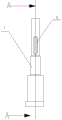
Fig. 2 is the structural representation of piercing punch of the present invention.
Fig. 3 is the cutaway view of piercing punch A-A face of the present invention.
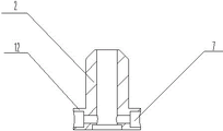
Fig. 4 is the cutaway view that the present invention turns over formula punch in advance.
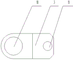
Fig. 5 is the top view of limiting plate of the present invention.
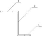
Fig. 6 is the front view of limiting plate of the present invention.
The specific embodiment
As shown in Figure 1, one is turned over shaping top nest punch assemblies in advance, comprise piercing punch 1, turn in advance formula punch 2, polyurethane pressure source cover 6, limiting plate 3, holder 4 and holder backing plate 5, piercing punch 1 is fixedly connected on holder 4, polyurethane pressure source cover 6 is nested with in the outside lower end of piercing punch 1, turning in advance formula punch 2 is nested with in piercing punch 1 outside, and be placed in polyurethane pressure source and overlap 6 tops, the top of piercing punch 1 is lower than the top of turning in advance formula punch 2, piercing punch 1 epimere is provided with at least two keyways 9, described turning in advance, on formula punch 2, be provided with corresponding screw 12, turning in advance formula punch 2 is fixedly connected with piercing punch 1 use screw 7, turn in advance 2 times section diameters of formula punch and be greater than section diameter, Z-type limiting plate 3 one end be provided with turn in advance formula punch 2 on the circular hole 10 that matches of section diameter, the other end is provided with the circular hole 11 matching with screw 8, Z-type limiting plate one end is nested with is turning over formula punch 2 outsides in advance, and the other end is fixedly connected on holder 4 with screw 8.
During product, change the punching process of drift, according to punching process, change punch structure, piercing punch 1 caves in to be placed in and turns in advance formula punch 2 inside, turn in advance formula punch 2 and first contact with product, the punching again of first flange, thus avoid unnecessary wearing and tearing and the die case of drift of piercing punch 1 to wear and tear.

Claims (5)

1. one kind is turned over shaping top nest punch assemblies in advance, it is characterized in that: comprise piercing punch, turn in advance formula punch, pressure source cover, limiting plate and holder, piercing punch is fixedly connected on holder, pressure source cover is nested with in the outside lower end of piercing punch, turning in advance formula punch is nested with in piercing punch outside, and be placed in pressure source cover top, the top of piercing punch is lower than the top of turning in advance formula punch, turning in advance formula punch is fixedly connected with piercing punch, turn in advance section diameter under formula punch and be greater than section diameter, limiting plate one end be provided with turn in advance formula punch on the circular hole that matches of section diameter, limiting plate one end is nested with is turning over formula punch outside in advance, the other end is fixedly connected on holder.
2. the shaping top nest punch assemblies of turning in advance according to claim 1, is characterized in that: described piercing punch epimere is provided with at least two keyways, described turning in advance on formula punch, is provided with corresponding screw, turns in advance formula punch and is screwed and is connected with piercing punch.
3. the shaping top nest punch assemblies of turning in advance according to claim 1, is characterized in that: described pressure source cover is polyurethane sleeve or rectangular coil spring.
4. the shaping top nest punch assemblies of turning in advance according to claim 1, is characterized in that: described limiting plate is Z-type limiting plate.
5. the shaping top nest punch assemblies of turning in advance according to claim 1, is characterized in that: described holder bottom is provided with holder backing plate.
CN201310707929.3A 2013-12-20 2013-12-20 Turn in advance shaping top nest punch assemblies Active CN103722078B (en)

Priority Applications (1)

Application Number Priority Date Filing Date Title
CN201310707929.3A CN103722078B (en) 2013-12-20 2013-12-20 Turn in advance shaping top nest punch assemblies

Applications Claiming Priority (1)

Application Number Priority Date Filing Date Title
CN201310707929.3A CN103722078B (en) 2013-12-20 2013-12-20 Turn in advance shaping top nest punch assemblies

Publications (2)

Publication Number Publication Date
CN103722078A true CN103722078A (en) 2014-04-16
CN103722078B CN103722078B (en) 2016-05-04

Family

ID=50446508

Family Applications (1)

Application Number Title Priority Date Filing Date
CN201310707929.3A Active CN103722078B (en) 2013-12-20 2013-12-20 Turn in advance shaping top nest punch assemblies

Country Status (1)

Country Link
CN (1) CN103722078B (en)

Cited By (2)

* Cited by examiner, † Cited by third party
Publication number Priority date Publication date Assignee Title
CN108213214A (en) * 2017-12-29 2018-06-29 天津市津兆机电开发有限公司 Limiting structure for limiting displacement of floating template of mold
CN110756688A (en) * 2019-11-27 2020-02-07 鹤壁天淇汽车模具有限公司 A high-repeatability combined roller mechanism for new energy vehicle molds

Citations (8)

* Cited by examiner, † Cited by third party
Publication number Priority date Publication date Assignee Title
US4440052A (en) * 1980-09-12 1984-04-03 Unipunch Products, Inc. Punch assembly with unitary stripper spring assembly
CN101450358A (en) * 2007-12-06 2009-06-10 Umix株式会社 Puncher
US20100206150A1 (en) * 2009-02-19 2010-08-19 Pass Stanztechnik Ag Stamping tool
CN202185513U (en) * 2011-06-16 2012-04-11 北京永茂机电科技有限公司 Punch pressing block assembly
CN202984410U (en) * 2012-12-19 2013-06-12 培祐股份有限公司 punching die
CN103287500A (en) * 2013-06-25 2013-09-11 北京汽车股份有限公司 Top cover beam and forming die of top cover beam and machining method of top cover beam
CN203209529U (en) * 2013-04-15 2013-09-25 鹤壁天汽模汽车模具有限公司 Mechanism for flanging and subsequent punching
CN203737820U (en) * 2013-12-20 2014-07-30 鹤壁天淇汽车模具有限公司 Pre-flanging shaping concave-top male die assembly

Patent Citations (8)

* Cited by examiner, † Cited by third party
Publication number Priority date Publication date Assignee Title
US4440052A (en) * 1980-09-12 1984-04-03 Unipunch Products, Inc. Punch assembly with unitary stripper spring assembly
CN101450358A (en) * 2007-12-06 2009-06-10 Umix株式会社 Puncher
US20100206150A1 (en) * 2009-02-19 2010-08-19 Pass Stanztechnik Ag Stamping tool
CN202185513U (en) * 2011-06-16 2012-04-11 北京永茂机电科技有限公司 Punch pressing block assembly
CN202984410U (en) * 2012-12-19 2013-06-12 培祐股份有限公司 punching die
CN203209529U (en) * 2013-04-15 2013-09-25 鹤壁天汽模汽车模具有限公司 Mechanism for flanging and subsequent punching
CN103287500A (en) * 2013-06-25 2013-09-11 北京汽车股份有限公司 Top cover beam and forming die of top cover beam and machining method of top cover beam
CN203737820U (en) * 2013-12-20 2014-07-30 鹤壁天淇汽车模具有限公司 Pre-flanging shaping concave-top male die assembly

Non-Patent Citations (1)

* Cited by examiner, † Cited by third party
Title
钟翔山: "《图解冲压加工实用技术》", 31 May 2013, 化学工业出版社 *

Cited By (3)

* Cited by examiner, † Cited by third party
Publication number Priority date Publication date Assignee Title
CN108213214A (en) * 2017-12-29 2018-06-29 天津市津兆机电开发有限公司 Limiting structure for limiting displacement of floating template of mold
CN108213214B (en) * 2017-12-29 2020-05-08 天津市津兆机电开发有限公司 Limiting structure for limiting displacement of floating template of mold
CN110756688A (en) * 2019-11-27 2020-02-07 鹤壁天淇汽车模具有限公司 A high-repeatability combined roller mechanism for new energy vehicle molds

Also Published As

Publication number Publication date
CN103722078B (en) 2016-05-04

Similar Documents

Publication Publication Date Title
CN106181267B (en) The production technology of the automobile exhaust pipe of punching after a kind of first molding
CN103433377A (en) Blanking, punching, flanging and forming composite die
CN103722078B (en) Turn in advance shaping top nest punch assemblies
CN203791455U (en) Butt-punching tube piercing die
CN204365808U (en) A kind of cantilever punching die
CN203737820U (en) Pre-flanging shaping concave-top male die assembly
CN105834280A (en) Punch forming mold for steel wire check ring
CN203304396U (en) Drawing die capable of carrying out blank pressing
CN203887020U (en) Punching die
CN202934065U (en) Blank positioning structure of plate-type forge piece
CN202984463U (en) Motor enclosure drawing device
CN207770577U (en) A kind of transformer core cut-to-length quickly changes the mold hole punched device
CN204276635U (en) Steel cylinder punched hole punching pressure device
CN204004666U (en) A kind of water tap of gang welding moulding
CN104128519A (en) Pipe rotating and punching device
CN202343764U (en) Split type upper die at work station B of numerical control punch
CN201832936U (en) Locomotive deformed spring hook die
CN201493395U (en) Flange turning mold of engine oil measuring scale pipe
CN204035221U (en) Hanger general assembly single-piece hollow circular-tube internal diameter shaping mould after leaf spring
CN204429996U (en) A kind of two round shaped devices that interlock
CN203991936U (en) A kind of punching die
CN204262210U (en) One cuts expansion location-plate
CN203991917U (en) Straightening welding machine Special-purpose puncher
CN204308035U (en) Press Tools for Automobiles punching hole switching device
CN203356335U (en) Quick disassembly type flanging pre-punching punch device

Legal Events

Date Code Title Description
C06 Publication
PB01 Publication
C10 Entry into substantive examination
SE01 Entry into force of request for substantive examination
C14 Grant of patent or utility model
GR01 Patent grant
CB03 Change of inventor or designer information

Inventor after: Shi Bingxin

Inventor after: Jiao Haitao

Inventor after: Li Shaojun

Inventor after: Zhang Ge

Inventor after: Wu Xue

Inventor after: Cao Yonghui

Inventor after: Zheng Dongliang

Inventor after: Zhang Yong

Inventor after: Lu Xiaoliang

Inventor after: Chen Huihui

Inventor after: Wang Shengchang

Inventor after: Wang Weiwei

Inventor after: Wang Lei

Inventor before: Zheng Dongliang

Inventor before: Jiao Haitao

Inventor before: Li Shaojun

Inventor before: Zhang Ge

Inventor before: Wu Xue

Inventor before: Zhang Yong

Inventor before: Chen Huihui

Inventor before: Li Jianwen

Inventor before: Shi Bingxin

Inventor before: Wang Shengchang

Inventor before: Wang Weiwei

Inventor before: Zhang Wenxiao

Inventor before: Wang Lei

CB03 Change of inventor or designer information