CN103672659A - Vehicular lamp - Google Patents
Vehicular lamp Download PDFInfo
- Publication number
- CN103672659A CN103672659A CN201310414112.7A CN201310414112A CN103672659A CN 103672659 A CN103672659 A CN 103672659A CN 201310414112 A CN201310414112 A CN 201310414112A CN 103672659 A CN103672659 A CN 103672659A
- Authority
- CN
- China
- Prior art keywords
- light
- incident
- light guide
- light source
- plane
- Prior art date
- Legal status (The legal status is an assumption and is not a legal conclusion. Google has not performed a legal analysis and makes no representation as to the accuracy of the status listed.)
- Granted
Links
- 238000009792 diffusion process Methods 0.000 claims description 21
- 230000004048 modification Effects 0.000 description 16
- 238000012986 modification Methods 0.000 description 16
- 230000000694 effects Effects 0.000 description 7
- 238000002347 injection Methods 0.000 description 5
- 239000007924 injection Substances 0.000 description 5
- 238000010586 diagram Methods 0.000 description 4
- 239000004925 Acrylic resin Substances 0.000 description 1
- 229920000178 Acrylic resin Polymers 0.000 description 1
- 230000000052 comparative effect Effects 0.000 description 1
- 230000012447 hatching Effects 0.000 description 1
- 238000000034 method Methods 0.000 description 1
- 229920003002 synthetic resin Polymers 0.000 description 1
- 239000000057 synthetic resin Substances 0.000 description 1
Images


Classifications
-
- F—MECHANICAL ENGINEERING; LIGHTING; HEATING; WEAPONS; BLASTING
- F21—LIGHTING
- F21S—NON-PORTABLE LIGHTING DEVICES; SYSTEMS THEREOF; VEHICLE LIGHTING DEVICES SPECIALLY ADAPTED FOR VEHICLE EXTERIORS
- F21S43/00—Signalling devices specially adapted for vehicle exteriors, e.g. brake lamps, direction indicator lights or reversing lights
- F21S43/10—Signalling devices specially adapted for vehicle exteriors, e.g. brake lamps, direction indicator lights or reversing lights characterised by the light source
- F21S43/13—Signalling devices specially adapted for vehicle exteriors, e.g. brake lamps, direction indicator lights or reversing lights characterised by the light source characterised by the type of light source
- F21S43/14—Light emitting diodes [LED]
-
- F—MECHANICAL ENGINEERING; LIGHTING; HEATING; WEAPONS; BLASTING
- F21—LIGHTING
- F21S—NON-PORTABLE LIGHTING DEVICES; SYSTEMS THEREOF; VEHICLE LIGHTING DEVICES SPECIALLY ADAPTED FOR VEHICLE EXTERIORS
- F21S43/00—Signalling devices specially adapted for vehicle exteriors, e.g. brake lamps, direction indicator lights or reversing lights
- F21S43/20—Signalling devices specially adapted for vehicle exteriors, e.g. brake lamps, direction indicator lights or reversing lights characterised by refractors, transparent cover plates, light guides or filters
- F21S43/235—Light guides
- F21S43/236—Light guides characterised by the shape of the light guide
- F21S43/239—Light guides characterised by the shape of the light guide plate-shaped
-
- F—MECHANICAL ENGINEERING; LIGHTING; HEATING; WEAPONS; BLASTING
- F21—LIGHTING
- F21S—NON-PORTABLE LIGHTING DEVICES; SYSTEMS THEREOF; VEHICLE LIGHTING DEVICES SPECIALLY ADAPTED FOR VEHICLE EXTERIORS
- F21S43/00—Signalling devices specially adapted for vehicle exteriors, e.g. brake lamps, direction indicator lights or reversing lights
- F21S43/20—Signalling devices specially adapted for vehicle exteriors, e.g. brake lamps, direction indicator lights or reversing lights characterised by refractors, transparent cover plates, light guides or filters
- F21S43/235—Light guides
- F21S43/242—Light guides characterised by the emission area
- F21S43/243—Light guides characterised by the emission area emitting light from one or more of its extremities
-
- F—MECHANICAL ENGINEERING; LIGHTING; HEATING; WEAPONS; BLASTING
- F21—LIGHTING
- F21S—NON-PORTABLE LIGHTING DEVICES; SYSTEMS THEREOF; VEHICLE LIGHTING DEVICES SPECIALLY ADAPTED FOR VEHICLE EXTERIORS
- F21S43/00—Signalling devices specially adapted for vehicle exteriors, e.g. brake lamps, direction indicator lights or reversing lights
- F21S43/20—Signalling devices specially adapted for vehicle exteriors, e.g. brake lamps, direction indicator lights or reversing lights characterised by refractors, transparent cover plates, light guides or filters
- F21S43/235—Light guides
- F21S43/249—Light guides with two or more light sources being coupled into the light guide
-
- F—MECHANICAL ENGINEERING; LIGHTING; HEATING; WEAPONS; BLASTING
- F21—LIGHTING
- F21S—NON-PORTABLE LIGHTING DEVICES; SYSTEMS THEREOF; VEHICLE LIGHTING DEVICES SPECIALLY ADAPTED FOR VEHICLE EXTERIORS
- F21S43/00—Signalling devices specially adapted for vehicle exteriors, e.g. brake lamps, direction indicator lights or reversing lights
- F21S43/20—Signalling devices specially adapted for vehicle exteriors, e.g. brake lamps, direction indicator lights or reversing lights characterised by refractors, transparent cover plates, light guides or filters
- F21S43/26—Refractors, transparent cover plates, light guides or filters not provided in groups F21S43/235 - F21S43/255
-
- F—MECHANICAL ENGINEERING; LIGHTING; HEATING; WEAPONS; BLASTING
- F21—LIGHTING
- F21S—NON-PORTABLE LIGHTING DEVICES; SYSTEMS THEREOF; VEHICLE LIGHTING DEVICES SPECIALLY ADAPTED FOR VEHICLE EXTERIORS
- F21S43/00—Signalling devices specially adapted for vehicle exteriors, e.g. brake lamps, direction indicator lights or reversing lights
- F21S43/30—Signalling devices specially adapted for vehicle exteriors, e.g. brake lamps, direction indicator lights or reversing lights characterised by reflectors
- F21S43/31—Optical layout thereof
- F21S43/315—Optical layout thereof using total internal reflection
-
- F—MECHANICAL ENGINEERING; LIGHTING; HEATING; WEAPONS; BLASTING
- F21—LIGHTING
- F21S—NON-PORTABLE LIGHTING DEVICES; SYSTEMS THEREOF; VEHICLE LIGHTING DEVICES SPECIALLY ADAPTED FOR VEHICLE EXTERIORS
- F21S43/00—Signalling devices specially adapted for vehicle exteriors, e.g. brake lamps, direction indicator lights or reversing lights
- F21S43/30—Signalling devices specially adapted for vehicle exteriors, e.g. brake lamps, direction indicator lights or reversing lights characterised by reflectors
- F21S43/33—Signalling devices specially adapted for vehicle exteriors, e.g. brake lamps, direction indicator lights or reversing lights characterised by reflectors characterised by their material, surface treatment or coatings
-
- F—MECHANICAL ENGINEERING; LIGHTING; HEATING; WEAPONS; BLASTING
- F21—LIGHTING
- F21S—NON-PORTABLE LIGHTING DEVICES; SYSTEMS THEREOF; VEHICLE LIGHTING DEVICES SPECIALLY ADAPTED FOR VEHICLE EXTERIORS
- F21S43/00—Signalling devices specially adapted for vehicle exteriors, e.g. brake lamps, direction indicator lights or reversing lights
- F21S43/40—Signalling devices specially adapted for vehicle exteriors, e.g. brake lamps, direction indicator lights or reversing lights characterised by the combination of reflectors and refractors
-
- G—PHYSICS
- G02—OPTICS
- G02B—OPTICAL ELEMENTS, SYSTEMS OR APPARATUS
- G02B19/00—Condensers, e.g. light collectors or similar non-imaging optics
- G02B19/0004—Condensers, e.g. light collectors or similar non-imaging optics characterised by the optical means employed
- G02B19/0009—Condensers, e.g. light collectors or similar non-imaging optics characterised by the optical means employed having refractive surfaces only
- G02B19/0014—Condensers, e.g. light collectors or similar non-imaging optics characterised by the optical means employed having refractive surfaces only at least one surface having optical power
-
- G—PHYSICS
- G02—OPTICS
- G02B—OPTICAL ELEMENTS, SYSTEMS OR APPARATUS
- G02B19/00—Condensers, e.g. light collectors or similar non-imaging optics
- G02B19/0004—Condensers, e.g. light collectors or similar non-imaging optics characterised by the optical means employed
- G02B19/0028—Condensers, e.g. light collectors or similar non-imaging optics characterised by the optical means employed refractive and reflective surfaces, e.g. non-imaging catadioptric systems
-
- G—PHYSICS
- G02—OPTICS
- G02B—OPTICAL ELEMENTS, SYSTEMS OR APPARATUS
- G02B19/00—Condensers, e.g. light collectors or similar non-imaging optics
- G02B19/0033—Condensers, e.g. light collectors or similar non-imaging optics characterised by the use
- G02B19/0047—Condensers, e.g. light collectors or similar non-imaging optics characterised by the use for use with a light source
- G02B19/0061—Condensers, e.g. light collectors or similar non-imaging optics characterised by the use for use with a light source the light source comprising a LED
-
- G—PHYSICS
- G02—OPTICS
- G02B—OPTICAL ELEMENTS, SYSTEMS OR APPARATUS
- G02B5/00—Optical elements other than lenses
- G02B5/02—Diffusing elements; Afocal elements
- G02B5/0205—Diffusing elements; Afocal elements characterised by the diffusing properties
- G02B5/021—Diffusing elements; Afocal elements characterised by the diffusing properties the diffusion taking place at the element's surface, e.g. by means of surface roughening or microprismatic structures
-
- G—PHYSICS
- G02—OPTICS
- G02B—OPTICAL ELEMENTS, SYSTEMS OR APPARATUS
- G02B6/00—Light guides; Structural details of arrangements comprising light guides and other optical elements, e.g. couplings
- G02B6/0001—Light guides; Structural details of arrangements comprising light guides and other optical elements, e.g. couplings specially adapted for lighting devices or systems
- G02B6/0011—Light guides; Structural details of arrangements comprising light guides and other optical elements, e.g. couplings specially adapted for lighting devices or systems the light guides being planar or of plate-like form
- G02B6/0033—Means for improving the coupling-out of light from the light guide
Landscapes
- Engineering & Computer Science (AREA)
- Physics & Mathematics (AREA)
- General Engineering & Computer Science (AREA)
- Optics & Photonics (AREA)
- General Physics & Mathematics (AREA)
- Microelectronics & Electronic Packaging (AREA)
- Non-Portable Lighting Devices Or Systems Thereof (AREA)
- Planar Illumination Modules (AREA)
Abstract
一种车辆用灯具,其具备导光体,在提高来自光源的射出光的光利用效率的基础上有效地抑制发光不均匀的产生。在水平面内,导光体(20)的后面(20b)具备有:第一射入部(20A1),其把来自光源(22)的光向前方侧折射地进行射入;第二射入部(20A2),其在两侧向侧面折射地进行射入;左右一对反射部(20A3),其使该射入光朝向前方地进行内面反射,以提高光利用效率。而且,第一射入部在水平面内把来自光源的光作为扩散光射入,各反射部(20A3)在水平面内作为扩散光进行反射。由此,对于导光体的前面(20a)而使从第一射入部的射入光到达的区域和从各反射部的内面反射光到达的区域在在广阔的范围重叠而不形成暗部(D)。
A lamp for a vehicle includes a light guide, and effectively suppresses the occurrence of non-uniform light emission while improving the light utilization efficiency of light emitted from a light source. In the horizontal plane, the rear surface (20b) of the light guide body (20) is provided with: a first incident part (20A1), which refracts light from the light source (22) to the front side and injects it; a second incident part ( 20A2 ) is incident on both sides so as to be refracted sideways; and a pair of left and right reflectors ( 20A3 ) internally reflects the incident light toward the front to improve light utilization efficiency. Furthermore, the first incident portion injects the light from the light source as diffused light within the horizontal plane, and each reflection portion ( 20A3 ) reflects diffused light within the horizontal plane. Thereby, with respect to the front surface (20a) of the light guide body, the region where the incident light from the first incident part reaches and the region where the reflected light from the inner surface of each reflection part reaches overlaps in a wide range without forming a dark part ( D).
Description
技术领域technical field
本发明涉及具备导光体的车辆用灯具。The present invention relates to a vehicle lamp provided with a light guide.
背景技术Background technique
以往,作为具备导光体的车辆用灯具而例如知道有如“专利文献1”所记载的那样,把来自光源的射出光从导光体的后面射入,并使从其前面射出的结构。Conventionally, as a vehicle lamp including a light guide, for example, as described in "Patent Document 1", a configuration is known in which light emitted from a light source enters from the rear of the light guide and emits from the front.
“专利文献2”虽然是信号灯,但在上述那样的灯具结构中所记载的结构具备有:第一射入部,其导光体的后面把来自光源的光向前方侧折射地进行射入;第二射入部,其在该第一射入部的周围把来自光源的光向侧面折射地进行射入;反射部,其把从该第二射入部射入的来自光源的光朝向前方地进行内面反射。Although "Patent Document 2" is a signal lamp, the structure described in the above-mentioned lamp structure includes: the first incident part, the rear surface of the light guide body refracts the light from the light source to the front side and injects it; the second incident part, which refracts the light from the light source to the side around the first incident part; and the reflector, which directs the light from the light source incident from the second incident part toward the front internal reflection.
专利文献1:日本特开2007-250401号公报Patent Document 1: Japanese Patent Laid-Open No. 2007-250401
专利文献2:日本特开2006-48165号公报Patent Document 2: Japanese Patent Laid-Open No. 2006-48165
作为车辆用灯具的导光体,只要采用上述“专利文献2”所记载的结构,就能够提高来自光源的射出光的光利用效率。As the light guide body of the vehicle lamp, the light utilization efficiency of the light emitted from the light source can be improved as long as the structure described in the above-mentioned "Patent Document 2" is adopted.
但上述“专利文献2”所记载的导光体,其第一射入部是把来自光源的光作为朝向灯具正面方向的平行光来射入,且其反射部把从该第二射入部射入的来自光源的光作为朝向灯具正面方向的平行光来进行内面反射,因此,对于导光体的前面就成为分离有:从第一射入部的射入光到达的区域和从反射部的内面反射光到达的区域。因此,在从其前方观察导光体的前面时,在第一射入部与反射部之间就产生暗部,由于由此而产生导光体发光不均匀,所以存在灯具不太美观的问题。However, in the light guide described in the above-mentioned "Patent Document 2", the first incident part injects the light from the light source as parallel light toward the front of the lamp, and the reflective part receives the light from the second incident part. The incident light from the light source is internally reflected as parallel light toward the front of the lamp. Therefore, for the front of the light guide, there are separated areas: the area where the incident light arrives from the first incident part and the area where the incident light arrives from the reflective part. The area where reflected light reaches the inner surface of . Therefore, when the front of the light guide is viewed from the front, a dark portion is generated between the first incident portion and the reflection portion, and uneven light emission of the light guide is caused by this, so there is a problem that the lamp does not look good.
相对地,只要使光源的位置多少有些偏差,或者使第一射入部和反射部的表面形状多少变形,就能够缓和产生上述暗部。但问题在于即使采用这种结构,也不能有效地抑制导光体发光不均匀的产生。In contrast, the occurrence of the above-mentioned dark portion can be alleviated by slightly shifting the position of the light source or by slightly deforming the surface shapes of the first incident portion and the reflecting portion. However, the problem is that even if such a structure is adopted, the occurrence of non-uniform light emission of the light guide cannot be effectively suppressed.
发明内容Contents of the invention
本发明是鉴于这种情况而开发的,目的在于提供一种车辆用灯具,在具备导光体的车辆用灯具中,在提高来自光源的射出光的光利用效率的基础上,能够有效地抑制发光不均匀的产生。The present invention was developed in view of this situation, and its object is to provide a vehicle lamp that can effectively suppress the Occurrence of uneven light emission.
本发明通过对于导光体的结构进行了研究而来谋求达到上述目的。The present invention achieves the above object by studying the structure of the light guide.
本发明的车辆用灯具Vehicle lamp of the present invention
具备有:光源、把来自该光源的射出光从后面射入并从前面射出的导光体,其特点在于,It includes: a light source, a light guide that injects light emitted from the light source from the rear and emits it from the front, and is characterized in that
在向前后方向延伸的第一平面内,所述导光体的后面具备有:第一射入部,其把来自所述光源的光向前方侧折射地进行射入;第二射入部,其在该第一射入部的两侧把来自所述光源的光向侧面折射地进行射入;反射部,其把从该第二射入部射入的来自所述光源的光朝向前方进行内面反射,In the first plane extending in the front-rear direction, the rear surface of the light guide is provided with: a first incident part that refracts light from the light source to the front side and injects it; a second incident part that It refracts the light from the light source to the side on both sides of the first incident part; the reflector makes the light from the light source incident from the second incident part forward internal reflection,
所述第一射入部在所述第一平面内,把来自所述光源的光作为扩散光射入,The first incident portion injects the light from the light source as diffused light within the first plane,
所述反射部在所述第一平面内,把从所述第二射入部射入的来自所述光源的光作为扩散光反射。The reflective portion reflects the light from the light source incident from the second incident portion as diffused light within the first plane.
所述“光源”的种类没有特别的限定,例如能够采用发光二极管等。The type of the "light source" is not particularly limited, and for example, a light emitting diode or the like can be used.
所述“导光体”也可以是旋转体的结构,也可以是沿第一平面延伸的导光板结构。The "light guide body" may also be a structure of a rotating body, or a structure of a light guide plate extending along the first plane.
所述“第一平面”只要是向前后方向延伸的平面,其方向没有特别的限定。The direction of the "first plane" is not particularly limited as long as it is a plane extending in the front-back direction.
所述“第一射入部”只要是至少在第一平面内把来自光源的光作为扩散光射入,则在与第一平面交叉的平面内可以作为扩散光射入,也可以不作为扩散光射入。As long as the "first incident part" injects the light from the light source as diffused light in at least the first plane, it may be incident as diffused light in a plane intersecting the first plane, or not as diffused light. Light enters.
所述“反射部”只要是至少在第一平面内把从第二射入部射入的来自光源的光作为扩散光反射,则在与第一平面交叉的平面内可以作为扩散光反射,也可以不作为扩散光反射。As long as the "reflecting part" reflects the light from the light source incident from the second incident part as diffused light in at least the first plane, it may reflect as diffused light in a plane intersecting the first plane. May not be reflected as diffuse light.
如上述结构所示,本发明的车辆用灯具由于在向前后方向延伸的第一平面内,导光体的后面具备有:第一射入部,其把来自所述光源的光向前方侧折射地进行射入;第二射入部,其在该第一射入部的两侧把来自光源的光向侧面折射地进行射入;反射部,其把从该第二射入部射入的来自光源的光朝向前方地进行内面反射,所以能够提高来自光源的射出光的光利用效率。As shown in the above structure, in the vehicle lighting device of the present invention, in the first plane extending in the front-rear direction, the rear surface of the light guide is provided with a first incident portion that refracts the light from the light source to the front side. the second incident part, which refracts the light from the light source to the side on both sides of the first incident part; the reflection part, which injects the light incident from the second incident part Since the light from the light source is internally reflected forward, the light utilization efficiency of the light emitted from the light source can be improved.
这时,由于所述第一射入部在第一平面内,把来自光源的光作为扩散光射入,且所述反射部在第一平面内,把从第二射入部射入的来自光源的光作为扩散光反射,所以对于导光体的前面而能够使从第一射入部的射入光到达的区域和从反射部的内面反射光到达的区域在在广阔的范围重叠。因此,在从其前方观察导光体的前面时,能够可靠地防止在第一射入部与反射部之间产生暗部,由此,能够有效地抑制导光体发光不均匀的产生。At this time, since the first incident part is in the first plane, the light from the light source is incident as diffused light, and the reflection part is in the first plane, and the light from the second incident part is incident in the first plane. The light from the light source is reflected as diffused light, so that the area where the incident light from the first incident portion arrives and the area where the reflected light from the inner surface of the reflection portion arrives can overlap in a wide range with respect to the front surface of the light guide. Therefore, when the front of the light guide is viewed from the front, it is possible to reliably prevent a dark portion from being generated between the first incident portion and the reflection portion, thereby effectively suppressing the occurrence of non-uniform light emission of the light guide.
根据本发明,在具备导光体的车辆用灯具中,在提高来自光源的射出光的光利用效率的基础上,能够有效地抑制发光不均匀的产生。于是由此而能够提高灯具的美观。According to the present invention, in the vehicular lamp including the light guide, it is possible to effectively suppress the occurrence of non-uniform light emission while improving the light utilization efficiency of the light emitted from the light source. As a result, the aesthetics of the lamp can be improved.
在上述结构中,只要把导光体设定成沿第一平面延伸的导光板,则在从其前方观察该导光体的前面时,就能够看到带状发光。In the above structure, as long as the light guide is set as a light guide plate extending along the first plane, when the front of the light guide is viewed from the front, band-like light emission can be seen.
这时,在该导光体与光源之间只要包围光源地配置透镜,则即使在导光体是导光板的情况下,也能够把来自光源的射出光有效地向导光体射入。In this case, if a lens is disposed between the light guide and the light source so as to surround the light source, even when the light guide is a light guide plate, the emitted light from the light source can be efficiently entered into the light guide.
在该作为导光板构成的导光体的后面,只要把第一射入部、第二射入部和反射部沿第一平面形成多组,则在从其前方观察该导光体的前面时,就能够看到细长的带状发光。At the back of the light guide body configured as a light guide plate, as long as the first incident part, the second incident part, and the reflection part are formed in multiple groups along the first plane, when the front of the light guide body is viewed from the front, , you can see the slender band-like light.
在上述结构中,只要把导光体的前面作为光扩散面,就能够看到导光体更均匀地发光。In the above structure, if the front surface of the light guide is used as the light diffusion surface, it can be seen that the light guide emits light more uniformly.
在上述结构中,作为第一射入部的结构只要设定成在与第一平面正交的第二平面内把来自光源的光作为扩散光射入,作为反射部的结构只要设定成在第二平面内把从第二射入部射入的来自光源的光作为扩散光反射,则即使在第二平面内把导光体的前面形成为使光扩散,或者使其光扩散的程度变小的情况下,也能够使来自导光体前面的射出光向沿第二平面的方向扩散。且由此在灯具非亮灯时能够提高导光体的美观。这时,也能够把该结构仅应用第一射入部和反射部的任意一方。In the above-mentioned structure, the structure as the first incident part only needs to be set so that the light from the light source is incident as diffused light in the second plane perpendicular to the first plane, and the structure as the reflection part only needs to be set to be in the second plane perpendicular to the first plane. In the second plane, the light from the light source incident from the second incident portion is reflected as diffused light, even if the front surface of the light guide is formed in the second plane to diffuse the light, or the degree of light diffusion becomes smaller. Even if it is small, it is possible to diffuse the emitted light from the front surface of the light guide in the direction along the second plane. And thus, the appearance of the light guide body can be improved when the lamp is not on. In this case, it is also possible to apply this configuration to only one of the first incident portion and the reflective portion.
附图说明Description of drawings
图1是表示本发明一实施例车辆用灯具的平剖视图;FIG. 1 is a planar sectional view showing a vehicle lamp according to an embodiment of the present invention;
图2是图1的Ⅱ-Ⅱ线剖视图;Fig. 2 is a sectional view of line II-II of Fig. 1;
图3是把上述实施例的导光体作为单品而从斜上后方看并表示的立体图;Fig. 3 is a perspective view of the light guide of the above-mentioned embodiment as a single product viewed from the obliquely above and behind;
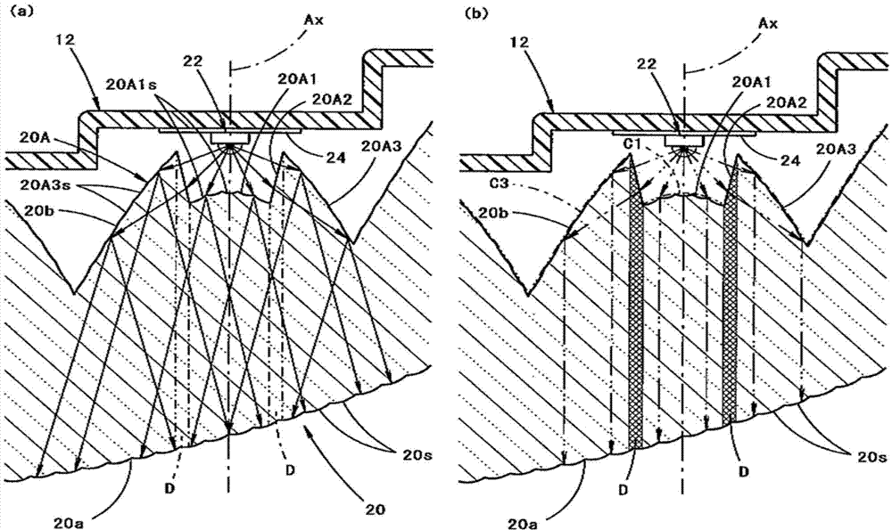
图4(a)是为了说明上述实施例的作用而把图1的一部分取出来表示的图,图4(b)表示其比较例,是与图4(a)同样的图;Fig. 4 (a) is to illustrate the effect of above-mentioned embodiment and take out the figure of a part of Fig. 1, Fig. 4 (b) shows its comparative example, is the same figure as Fig. 4 (a);
图5表示上述实施例的第一变形例车辆用灯具的主要部分,是与图4(a)同样的图;Fig. 5 shows the main part of the vehicle lamp according to the first modified example of the above-mentioned embodiment, and is the same diagram as Fig. 4(a);
图6是图5的Ⅵ-Ⅵ线剖视图;Fig. 6 is a sectional view of line VI-VI of Fig. 5;
图7是表示上述实施例的第二变形例车辆用灯具主要部分的平剖视图;7 is a planar cross-sectional view showing a main part of a vehicle lamp according to a second modified example of the above-mentioned embodiment;
图8(a)是图7的Ⅷ(a)-Ⅷ(a)线剖视图;图8(b)是图7的Ⅷ(b)-Ⅷ(b)线剖视图;Fig. 8 (a) is the sectional view of the VIII (a)-VIII (a) line of Fig. 7; Fig. 8 (b) is the sectional view of the VIII (b) - VIII (b) line of Fig. 7;
图9(a)和(b)表示上述实施例的第三变形例,是与图8(a)和(b)同样的图;Fig. 9 (a) and (b) represent the third modified example of the above embodiment, which are the same figures as Fig. 8 (a) and (b);
图10(a)和(b)表示上述实施例的第四变形例,是与图8(a)和(b)同样的图;Fig. 10 (a) and (b) represent the fourth modified example of the above embodiment, which are the same figures as Fig. 8 (a) and (b);
图11表示上述实施例的第五变形例,是与图6同样的图。FIG. 11 shows a fifth modified example of the above-mentioned embodiment, and is the same view as FIG. 6 .
具体实施方式Detailed ways
图1是表示本发明一实施例车辆用灯具10的平剖视图;图2是图1的Ⅱ-Ⅱ线剖视图;Fig. 1 is a planar sectional view showing a
如这些图所示,本实施例的车辆用灯具10是设置在车辆右后端部的尾灯,在由灯体12和安装在该灯体12前端开口部的透明状透光罩14所形成的灯室内,被组装有三个光源22和导光体20。As shown in these figures, the
在图1中,作为车辆用灯具10,X所表示的方向是“前方”(作为车辆则是“后方”),Y所表示的方向是与“前方”正交的“右方向”。In FIG. 1 , as the
透光罩14被形成为从其左端部朝向右端部地向后方侧绕回。The
三个光源22都是红色的发光二极管,以使其发光面朝向前方的状态配置在导光体20的后方附近。这时,把这三个光源22在同一水平面上在左右方向等间隔地配置,且配置成越位于右侧则越向后方位移。这些各光源22被光源支承部件24所支承,这些各光源支承部件24被灯体12所支承。The three
图3是把导光体20作为单品而从斜上后方看并表示的立体图。FIG. 3 is a perspective view showing the
也如该图所示,导光体20是由丙烯酸树脂等构成的透明合成树脂成形品,是作为沿水平面延伸的导光板构成。该导光体20把来自各光源22的射出光从其后面20b射入并从其前面20a射出。在该导光体20的左右两端部形成有凸缘部20c,这左右一对凸缘部20c被灯体12所支承。As also shown in the figure, the
该导光体20的前面20a被形成为沿透光罩14而从左端部朝向右端部并向后方侧绕回。这时,该前面20a使从后面20b射入并到达该前面20a的来自各光源22的射出光向上下和左右方向扩散以成为光扩散面。具体说就是,在该前面20a以上下两段形成有多个鱼眼透镜状的扩散透镜元件20s。The
另一方面,导光体20的后面20b在左右方向的三个部位邻接地形成有用于控制来自各光源22射出光的光控制部20A。这时,把这三个光控制部20A配置成越位于右侧则越向后方位移。On the other hand, on the
这三个光控制部20A都具有同样的结构。于是以下说明位于中央的光控制部20A。These three
图4(a)是包含位于中央的光控制部20A地把导光体20的一部分取出来表示的与图1同样的图。FIG. 4( a ) is a diagram similar to FIG. 1 , showing a part of the
也如该图图4(a)所示,光控制部20A在水平面内具备有:第一射入部20A1,其把来自光源22的光向前方侧折射地进行射入;左右一对的第二射入部20A2,其在该第一射入部20A1的两侧把来自光源22的光向侧面折射地进行射入;左右一对的反射部20A3,其把从这些各第二射入部20A2射入的来自光源22的光朝向前方利用全反射进行内面反射。Also as shown in FIG. 4( a ) of the same figure, the
这时,第一射入部20A1被形成在左右跨越向前后方向延伸的轴线Ax的区域,而通过光源22发光中心。In this case, the first incident portion 20A1 is formed in a region spanning the axis Ax extending in the front-rear direction to the left and right, and passes through the light emission center of the
该第一射入部20A1把来自光源22的光不向上下方向扩散而作为向左右方向扩散的光进行射入。具体说就是,该第一射入部20A1相对于把来自光源22的光作为与轴线Ax平行的光进行射入的曲面(即向后方凸的曲面)而纵条纹状地形成有多个扩散透镜元件20A1s。The first incident portion 20A1 injects the light from the
左右一对第二射入部20A2由从第一射入部20A1的左右两端边缘向后方左右稍微扩展延伸的铅直面构成。The pair of left and right second injection parts 20A2 is constituted by a vertical surface that slightly extends left and right from the left and right end edges of the first injection part 20A1 to the rear.
左右一对反射部20A3被形成为从各第二射入部20A2的后端边缘朝向前方地向左右扩展。这时,这些各反射部20A3相对把来自第二射入部20A2的射入光作为与轴线Ax平行的光进行反射的曲面(即向后方凸的曲面)而纵条纹状地形成有多个扩散透镜元件20A3s,由此,把来自第二射入部20A2的射入光不向上下方向扩散而作为向左右方向扩散的光进行反射。The left and right pair of reflective portions 20A3 are formed so as to spread to the left and right from the rear end edge of each second incident portion 20A2 toward the front. At this time, these reflective portions 20A3 are formed in vertical stripes with a plurality of diffused surfaces relative to a curved surface (that is, a curved surface convex rearward) that reflects incident light from the second incident portion 20A2 as light parallel to the axis Ax. The lens element 20A3s thereby reflects the incident light from the second incident portion 20A2 as light diffused in the left and right directions without being diffused in the vertical direction.
下面说明本实施例的作用效果。The function and effect of this embodiment will be described below.
本实施例的车辆用灯具10由于导光体20的后面20b在水平面(即向前后方向延伸的第一平面)内具备有:第一射入部20A1,其把来自光源22的光向前方侧折射地进行射入;第二射入部20A2,其在该第一射入部20A1的两侧把来自光源22的光向侧面折射地进行射入;反射部20A3,其把从该第二射入部20A2射入的来自光源22的光朝向前方地进行内面反射,所以能够提高来自光源22的射出光的光利用效率。In the
这时,由于第一射入部20A1在水平面内把来自光源22的光作为扩散光射入,且反射部20A3在水平面内把从第二射入部20A2射入的来自光源22的光作为扩散光反射,所以能够得到下面的作用效果。At this time, since the first incident part 20A1 enters the light from the
即如图4(b)所示,第一射入部20A1假如由把来自光源22的光作为与轴线Ax平行的光进行射入的曲面C1所构成,且反射部20A3假如由把来自第二射入部20A2射入的来自光源22的光作为与轴线Ax平行的光进行反射的曲面C3所构成时,则对于导光体20的前面20a在第二射入部20A2的左右宽度部分就分离为:从第一射入部20A1的射入光到达的区域和从反射部20A3的内面反射光到达的区域。于是,在从其前方观察导光体20的前面20a时,该部分(即图中网线所示的部分)就作为暗部D被看到。That is, as shown in FIG. 4(b), if the first incident portion 20A1 is composed of a curved surface C1 that injects the light from the
相对地如图4(a)所示,由于本实施例中,第一射入部20A1在水平面内把来自光源22的光作为扩散光射入,且反射部20A3在水平面内把从第二射入部20A2射入的来自光源22的光作为扩散光反射,所以对于导光体20的前面20a而能够使从第一射入部20A1的射入光到达的区域和从反射部20A3的内面反射光到达的区域在广阔的范围重叠。因此,在从其前方观察导光体20的前面20a时,能够可靠地防止在第一射入部20A1与反射部20A3之间产生暗部D,由此,能够有效地抑制发光不均匀的产生。In contrast, as shown in Figure 4(a), in this embodiment, the first incident part 20A1 injects the light from the
根据本实施例,在具备导光体20的车辆用灯具10中,在对于来自光源22的射出光而提高光利用效率的基础上能够有效地抑制发光不均匀的产生。于是由此而能够提高灯具的美观。According to the present embodiment, in the
且本实施例中,由于把导光体20设定成沿水平面延伸的导光板,所以在从其前方观察该导光体20的前面20a时,能够看到横长的带状发光。In this embodiment, since the
特别是本实施例中,由于在导光体20的后面20b把第一射入部20A1、第二射入部20A2和反射部20A3沿水平面而形成有三组,所以在从其前方观察该导光体20的前面20a时,能够在水平方向看到细长的带状发光。Especially in this embodiment, since the first incident portion 20A1, the second incident portion 20A2, and the reflective portion 20A3 are formed into three groups along the horizontal plane on the
且本实施例中,由于把导光体20的前面20a作为光扩散面,所以能够看到导光体20更均匀地发光。In addition, in this embodiment, since the
上述实施例说明了车辆用灯具10是设置在车辆右后端部的尾灯的情况,但与设置在车辆的部位和功能无关,通过采用与上述实施例同样的结构则能够得到与上述实施例同样的作用效果。例如作为车辆用灯具10,在尾灯以外,例如制动灯、白昼运转灯、车宽灯等也能够采用。这时,为了与这些各灯具的功能相符,除了红色的发光二极管之外,也可以使用白色和红棕色的发光二极管。The above-mentioned embodiment has described the case where the
下面说明上述实施例的变形例。Modifications of the above-described embodiment will be described below.
首先说明上述实施例的第一变形例。First, a first modification of the above-described embodiment will be described.
图5是表示本变形例车辆用灯具110主要部分的平剖视图。图6是图5的Ⅵ-Ⅵ线剖视图。FIG. 5 is a planar cross-sectional view showing main parts of a
如这些图所示,本变形例的车辆用灯具110,其基本结构也与上述实施例的情况相同,但在导光体120与光源22之间把光源22包围地配置有透镜130的点与上述实施例不同。As shown in these figures, the
透镜130由把光源22的发光中心作为中心而沿水平面圆弧状延伸的环状透镜构成。这时,该透镜130的其前面130a的铅直剖视形状是由凸曲线构成,其后面130b的铅直剖视形状是由直线构成。该透镜130一方面把来自光源22的射出光作为在铅直面内不向上下方向扩散的平行光射出,一方面在水平面内不偏向地原封不动成放射状射出。The
该透镜130其圆弧状延伸方向的两端面130c位于在从轴线Ax各向左右两侧旋转90°的位置,这左右一对两端面130c经由左右一对的透镜支承部件132而被支承在光源支承部件24。The two ends 130c of the
导光体120的其基本结构与上述实施例的导光体20相同,但在其后面130b的铅直剖视形状不是凸曲线而是由直线构成的点与上述实施例的情况不同。The basic structure of the
但即使在该导光体120上,也与上述实施例的导光体20相同,在其后面120b形成有由第一射入部120A1,第二射入部120A2和反射部120A3构成的光控制部120A。且在第一射入部20A1纵条纹状地形成有多个扩散透镜元件120A1s,由此而使来自透镜130的射出光作为不向上下方向扩散而向左右方向扩散的光射入。且在各反射部120A3纵条纹状地形成有多个扩散透镜元件120A3s,由此而使从第二射入部120A2射入的来自透镜130的射出光作为不向上下方向扩散而向左右方向扩散的光进行反射。However, even on this
该导光体120的前面120a与上述实施例的导光体20相同,通过形成有多个扩散透镜元件120s而构成光扩散面。The
透镜130被配置在由第一射入部120A1和其两侧的第二射入部120A2所包围的空间。The
通过采用本变形例的结构,与把导光体20设定成导光板无关地能够把来自光源22的射出光高效率地向导光体20射入。即,能够把来自光源22的射出光更多地向导光体20射入,且能够使在透镜130的后面130b和前面130a的光偏转量小于在上述实施例导光体20的后面20b的光偏转量,缩小由表面反射引起的损失。By employing the configuration of this modified example, the emitted light from the
接着说明上述实施例的第二变形例。Next, a second modified example of the above-described embodiment will be described.
图7是表示本变形例车辆用灯具210主要部分的平剖视图。图8(a)是图7的Ⅷ(a)-Ⅷ(a)线剖视图;图8(b)是图7的Ⅷ(b)-Ⅷ(b)线剖视图。FIG. 7 is a planar cross-sectional view showing a main part of a vehicle lamp 210 according to this modified example. Fig. 8(a) is a sectional view taken along line VIII(a)-VIII(a) of Fig. 7; Fig. 8(b) is a sectional view taken along line VIII(b)-VIII(b) of Fig. 7 .
如这些图所示,本变形例的车辆用灯具210,其基本结构也与上述第一变形例的情况相同,但导光体220的后面220b和前面220a的表面形状与上述第一变形例导光体120的情况不同。As shown in these figures, the basic structure of the vehicle lamp 210 of this modified example is also the same as that of the above-mentioned first modified example, but the surface shapes of the
即,本变形例的导光体220也在其后面220b形成有由第一射入部220A1,第二射入部220A2和反射部220A3构成的光控制部220A。但其第一射入部220A1和各反射部220A3都是由单一的曲面构成。That is, the
这时如图7所示,第一射入部220A1的其水平剖视形状被形成凸曲线状,其曲率被设定成这样大小:使来自透镜130的射出光作为多少向左右方向扩散的光进行射入。另一方面,也如图7所示,各反射部220A3的其水平剖视形状被形成凸曲线状,其曲率被设定成这样大小:使从第二射入部220A2射入的来自透镜130的射出光作为稍微向左右方向扩散的光进行反射。At this time, as shown in FIG. 7 , the horizontal cross-sectional shape of the first incident portion 220A1 is formed in a convex curve shape, and its curvature is set so that the emitted light from the
于是由此,对于导光体220的前面220a而能够使从第一射入部220A1的射入光到达的区域和从反射部220A3的内面反射光到达的区域重叠。Accordingly, with respect to the
如图8(a)所示,第一射入部220A1的其铅直剖视形状被形成凹曲线状,使来自透镜130的射出光作为向上下方向扩散的光进行射入。另一方面,也如图8(b)所示,各反射部220A3的其铅直剖视形状被形成凹曲线状,使从第二射入部220A2射入的来自透镜130的射出光作为向上下方向扩散的光进行反射。As shown in FIG. 8( a ), the vertical cross-sectional shape of the first incident portion 220A1 is formed in a concave curve shape, and the emitted light from the
于是由此,使来自第一射入部220A1的射入光和被各反射部220A3反射的光,在其一部分利用导光体220的上面220d或下面220e全反射而进行内面反射后,使作为向上下方向扩散的光而到达前面220a。Accordingly, the incident light from the first incident portion 220A1 and the light reflected by each reflection portion 220A3 are partially reflected by the
如图7所示,本变形例导光体220的其前面220a也作为光扩散面构成,使从其后面220b射入而到达该前面220a的来自各光源22的射出光向左右方向扩散。具体说就是,在该前面220a纵条纹状地形成有多个柱面透镜状的扩散透镜元件220s。As shown in FIG. 7, the
由此而使到达前面220a的来自第一射入部220A1和各反射部120A3的扩散光通过多个扩散透镜元件220s而作为更大地向左右方向扩散的光射出。As a result, the diffused light from the first incident portion 220A1 and each reflective portion 120A3 that reaches the
即使采用本变形例结构的情况下,由于对于导光体220的前面220a而能够使从第一射入部220A1的射入光到达的区域和从各反射部220A3的内面反射光到达的区域重叠,所以在从其前方观察导光体220的前面220a时,能够可靠地防止在第一射入部220A1与各反射部120A3之间产生暗部,由此而能够有效地抑制发光不均匀的产生。Even in the case of the structure of this modified example, because of the
本变形例中,由于第一射入部220A1使来自透镜130的射出光作为向上下方向扩散的光进行射入,而且各反射部220A3使从第二射入部220A2射入的来自透镜130的射出光作为向上下方向扩散的光进行反射,所以尽管形成在导光体220的前面220a的多个扩散透镜元件220s不具有上下方向的光扩散功能,但也能够把来自其前面220a的射出光变成向上下方向扩散的光。In this modified example, since the first incident part 220A1 makes the exit light from the
且如本变形例这样,通过使前面220a纵条纹状地形成有多个圆柱透镜状的扩散透镜元件220s,则能够提高灯具非亮灯时导光体220的美观。Furthermore, by forming a plurality of cylindrical lens-shaped
接着说明上述实施例的第三变形例。Next, a third modified example of the above-described embodiment will be described.
图9(a)和(b)表示本变形例车辆用灯具的主要部分,是与图8(a)和(b)同样的图。FIGS. 9( a ) and ( b ) show main parts of the vehicle lamp according to the modification, and are the same as FIGS. 8( a ) and ( b ).
如这些图所示,本变形例的车辆用灯具,其基本结构与上述第二变形例的情况相同,但导光体320的后面320b的第一射入部320A1和各反射部320A3的铅直剖视形状与上述第二变形例导光体220的情况不同。As shown in these figures, the basic structure of the vehicular lamp of this modified example is the same as that of the above-mentioned second modified example, but the first incident portion 320A1 of the
即本变形例的第一射入部320A1的铅直剖视形状具有由四个凹曲线形成的四个透镜元件,且各反射部320A3的铅直剖视形状具有由四个凹曲线形成的四个反射元件。That is, the vertical cross-sectional shape of the first incident portion 320A1 in this modified example has four lens elements formed by four concave curves, and the vertical cross-sectional shape of each reflection portion 320A3 has four lens elements formed by four concave curves. a reflective element.
于是,这些四个透镜元件和反射元件使来自第一射入部320A1的射入光和被各反射部320A3反射的光,在其一部分利用导光体320的上面320d或下面320e全反射而进行内面反射后,使作为向上下方向扩散的光而到达前面320a。Then, these four lens elements and reflective elements completely reflect the incident light from the first incident portion 320A1 and the light reflected by each reflective portion 320A3 by the
即使在采用本变形例结构的情况下,尽管形成在导光体320的前面320a的多个扩散透镜元件320s不具有上下方向的光扩散功能,但也能够把来自其前面320a的射出光变成向上下方向扩散的光。且由此能够得到与上述第二变形例的情况同样的作用效果。Even in the case of adopting the structure of this modified example, although the plurality of
接着说明上述实施例的第四变形例。Next, a fourth modified example of the above-described embodiment will be described.
图10(a)和(b)表示本变形例车辆用灯具的主要部分,是与图8(a)和(b)同样的图。FIGS. 10( a ) and ( b ) show main parts of the vehicle lamp according to the present modified example, and are the same diagrams as FIGS. 8( a ) and ( b ).
如这些图所示,本变形例的车辆用灯具,其基本结构与上述第二变形例的情况相同,但导光体420的后面420b的第一射入部420A1和各反射部420A3的铅直剖视形状与上述第二变形例导光体220的情况不同。As shown in these figures, the basic structure of the vehicle lamp of this modified example is the same as that of the above-mentioned second modified example, but the first incident portion 420A1 of the
即本变形例的第一射入部420A1的铅直剖视形状具有由四个凸曲线形成的四个透镜元件,且各反射部420A3的铅直剖视形状具有由四个凸曲线形成的四个反射元件。That is, the vertical cross-sectional shape of the first incident part 420A1 in this modification has four lens elements formed by four convex curves, and the vertical cross-sectional shape of each reflection part 420A3 has four convex curves formed by each. a reflective element.
于是,这些四个透镜元件和反射元件使来自第一射入部420A1的射入光和被各反射部420A3反射的光,在通过了各透镜元件和各反射元件的焦点位置或其近旁后,其一部分利用导光体420的上面420d或下面420e全反射而进行内面反射,使作为向上下方向扩散的光而到达前面420a。Then, these four lens elements and reflective elements make the incident light from the first incident portion 420A1 and the light reflected by each reflective portion 420A3 pass through the focal position or the vicinity of each lens element and each reflective element, A part thereof is totally reflected by the
即使采用本变形例结构的情况下,尽管在导光体420的前面420a形成有多个不具有上下方向光扩散功能的扩散透镜元件420s,但也能够把来自前面420a的射出光变成向上下方向扩散的光。且由此能够得到与上述第二变形例的情况同样的作用效果。Even in the case of the structure of this modified example, although a plurality of
接着说明上述实施例的第五变形例。Next, a fifth modified example of the above-described embodiment will be described.
图11表示本变形例车辆用灯具510的主要部分,是与图6同样的图。FIG. 11 shows a main part of a
如该图所示,本变形例的车辆用灯具510,其基本结构与上述第一变形例的情况相同,但导光体520的铅直剖视形状与上述第一变形例导光体220的情况不同。As shown in the figure, the
即本变形例的导光体520其上面520d和下面520e被形成向前方并且上下宽度逐渐变狭窄的锥状。That is, in the
本变形例的导光体520其后面520b的第一射入部520A1的铅直剖视形状被形成凸曲线状,使来自透镜130的射出光作为在上下方向稍微收敛的光射入。这时,其凸曲线的曲率大小被这样设定:使来自该第一射入部520A1的射入光收敛程度与导光体520上下宽度的狭窄程度大致一致。In the
本变形例导光体520的其前面520a也作为光扩散面构成,使从其后面520b射入而到达该前面520a的来自透镜130的射出光向左右方向扩散。具体说就是,在该前面520a纵条纹状地形成有多个扩散透镜元件520s。这时,该前面520a的铅直剖视形状被形成凸曲线状,由此而使到达该前面520a的光向上下方向扩散。The
本变形例的导光体520中,位于其各反射部(未图示)的铅直剖视形状也具有与位于第一射入部520A1的铅直剖视形状相同的铅直剖视形状。In the
即使在采用本变形例结构的情况下,也能够得到与上述第一变形例的情况同样的作用效果。Even in the case where the configuration of the present modification is adopted, the same effects as those of the first modification described above can be obtained.
如本变形例这样,通过把导光体520设定成形成锥状的导光板,能够看到其前面520a更明亮的发光。By setting the
在上述实施例及其变形例中作为各种要素表示数值不过是一例,当然也可以把它们适当地设定成不同的值。The numerical values shown as various elements in the above-described embodiments and their modifications are merely examples, and of course, they may be appropriately set to different values.
本发明并不限定于上述实施例及其变形例所记载的结构,能够采用加有此以外各种变更的结构。The present invention is not limited to the configurations described in the above-mentioned embodiments and modifications thereof, and configurations with various modifications other than these can be employed.
符号说明Symbol Description
10、110、210、510车辆用灯具 12灯体 14透光罩10, 110, 210, 510 lamps for
20、120、220、320、420、520导光体20, 120, 220, 320, 420, 520 light guide
20A、120A、220A光控制部20A, 120A, 220A light control unit
20A1、120A1、220A1、320A1、420A1、520A1第一射入部20A1, 120A1, 220A1, 320A1, 420A1, 520A1 first injection part
20A1s、20A3s、120A1s、120A3s扩散透镜元件20A1s, 20A3s, 120A1s, 120A3s diffuser lens elements
20A2、120A2、220A2第二射入部20A2, 120A2, 220A2 second injection part
20A3、120A3、220A3、320A3、420A3反射部20A3, 120A3, 220A3, 320A3, 420A3 reflector
20a、120a、220a、320a、420a、520a前面Front of 20a, 120a, 220a, 320a, 420a, 520a
20b、120b、220b、320b、420b、520b后面Behind 20b, 120b, 220b, 320b, 420b, 520b
20c凸缘部20c Flange
20s、120s、220s、320s、420s、520s扩散透镜元件(光扩散面)20s, 120s, 220s, 320s, 420s, 520s diffusion lens element (light diffusion surface)
22光源 24光源支承部件 130透镜22
130a前面 130b后面 130c两端面 132透镜支承部件130a front 130b rear 130c both ends 132 lens supporting part
220d、320d、420d、520d上面Above 220d, 320d, 420d, 520d
220e、320e、420e、520e下面Below 220e, 320e, 420e, 520e
Ax轴线 D暗部Ax axis D dark part
Claims (6)
Applications Claiming Priority (6)
| Application Number | Priority Date | Filing Date | Title |
|---|---|---|---|
| JPJP2012-201926 | 2012-09-13 | ||
| JP2012-201926 | 2012-09-13 | ||
| JP2012201926 | 2012-09-13 | ||
| JPJP2013-083556 | 2013-04-12 | ||
| JP2013-083556 | 2013-04-12 | ||
| JP2013083556A JP6203519B2 (en) | 2012-09-13 | 2013-04-12 | Vehicle lighting |
Publications (2)
| Publication Number | Publication Date |
|---|---|
| CN103672659A true CN103672659A (en) | 2014-03-26 |
| CN103672659B CN103672659B (en) | 2016-08-17 |
Family
ID=49212573
Family Applications (1)
| Application Number | Title | Priority Date | Filing Date |
|---|---|---|---|
| CN201310414112.7A Active CN103672659B (en) | 2012-09-13 | 2013-09-12 | Lamps apparatus for vehicle |
Country Status (4)
| Country | Link |
|---|---|
| US (1) | US20140071703A1 (en) |
| EP (1) | EP2708800A3 (en) |
| JP (1) | JP6203519B2 (en) |
| CN (1) | CN103672659B (en) |
Cited By (10)
| Publication number | Priority date | Publication date | Assignee | Title |
|---|---|---|---|---|
| CN105508957A (en) * | 2014-10-08 | 2016-04-20 | 株式会社小糸制作所 | Light emitting device and vehicle lamp |
| CN106415121A (en) * | 2014-06-27 | 2017-02-15 | 松下知识产权经营株式会社 | Lighting device and lighting method |
| CN106439663A (en) * | 2015-08-05 | 2017-02-22 | 深圳市银盾科技开发有限公司 | Environment-friendly automotive illumination lamp |
| CN108800052A (en) * | 2018-04-20 | 2018-11-13 | 长春海拉车灯有限公司 | A kind of light guide and the car light with the light guide |
| CN109990243A (en) * | 2017-12-29 | 2019-07-09 | 法雷奥照明湖北技术中心有限公司 | Lighting device for motor vehicle and motor vehicle |
| WO2019227938A1 (en) * | 2018-06-01 | 2019-12-05 | 深圳市绎立锐光科技开发有限公司 | Light source module |
| CN110701566A (en) * | 2018-07-10 | 2020-01-17 | 株式会社小糸制作所 | Vehicle lamps |
| CN112136000A (en) * | 2018-05-22 | 2020-12-25 | 市光工业株式会社 | Vehicle lamp |
| CN113785157A (en) * | 2019-03-22 | 2021-12-10 | Lg伊诺特有限公司 | Lighting module and lighting device including the same |
| CN114754326A (en) * | 2022-05-12 | 2022-07-15 | 常州星宇车灯股份有限公司 | Auxiliary lighting device applied to car lamp and using method thereof |
Families Citing this family (38)
| Publication number | Priority date | Publication date | Assignee | Title |
|---|---|---|---|---|
| JP6127538B2 (en) * | 2013-01-25 | 2017-05-17 | 市光工業株式会社 | Vehicle lighting |
| DE102013218739A1 (en) * | 2013-09-18 | 2015-03-19 | Automotive Lighting Reutlingen Gmbh | Lighting device of a motor vehicle |
| TW201525363A (en) * | 2013-12-18 | 2015-07-01 | 堤維西交通工業股份有限公司 | Light collecting light guide |
| JP6341771B2 (en) * | 2014-06-16 | 2018-06-13 | 株式会社小糸製作所 | Vehicle lighting |
| DE102014218991A1 (en) * | 2014-09-22 | 2016-03-24 | Automotive Lighting Reutlingen Gmbh | Luminaire for a motor vehicle |
| JP6422732B2 (en) | 2014-10-24 | 2018-11-14 | スタンレー電気株式会社 | Vehicle lighting |
| JP6548887B2 (en) | 2014-10-24 | 2019-07-24 | スタンレー電気株式会社 | Vehicle lamp |
| EP3076069B1 (en) * | 2015-03-31 | 2020-03-11 | Seoul Semiconductor Co., Ltd. | Light device of vehicle |
| JP6517078B2 (en) * | 2015-04-28 | 2019-05-22 | 株式会社小糸製作所 | Vehicle lamp |
| DE102015213830A1 (en) * | 2015-07-22 | 2017-01-26 | Automotive Lighting Reutlingen Gmbh | optical head |
| ITUB20156264A1 (en) * | 2015-12-04 | 2017-06-04 | Automotive Lighting Italia S P A A Socio Unico | LIGHTING DEVICE FOR VEHICLES |
| JP6761668B2 (en) * | 2016-05-17 | 2020-09-30 | 株式会社小糸製作所 | Vehicle lighting |
| EP3517826B1 (en) * | 2016-09-21 | 2023-12-27 | EXA Electronics Co., Ltd. | Lighting member using light-guiding film |
| WO2018172140A1 (en) * | 2017-03-21 | 2018-09-27 | Lumileds Holding B.V. | Optical module and automotive frontlighting system for motor vehicle |
| JP6894762B2 (en) * | 2017-05-24 | 2021-06-30 | スタンレー電気株式会社 | Vehicle lighting |
| CN109143449B (en) * | 2017-06-15 | 2021-03-26 | 市光法雷奥(佛山)汽车照明系统有限公司 | Light guide device, lighting device and motor vehicle |
| DE102017115899B4 (en) * | 2017-07-14 | 2023-11-02 | Automotive Lighting Reutlingen Gmbh | Motor vehicle light and motor vehicle headlight with such a light |
| DE102017128841B4 (en) * | 2017-12-05 | 2020-08-20 | Dr. Ing. H.C. F. Porsche Aktiengesellschaft | Light guide body for a lighting device of a motor vehicle |
| JP7017394B2 (en) * | 2017-12-14 | 2022-02-08 | 株式会社小糸製作所 | Light guide device |
| KR102446507B1 (en) * | 2017-12-29 | 2022-09-23 | 에스엘 주식회사 | car lamp |
| JP7081977B2 (en) | 2018-05-17 | 2022-06-07 | スタンレー電気株式会社 | Vehicle lighting |
| JP7079654B2 (en) | 2018-05-17 | 2022-06-02 | スタンレー電気株式会社 | Vehicle lighting |
| JP7211655B2 (en) * | 2018-06-04 | 2023-01-24 | スタンレー電気株式会社 | vehicle lamp |
| DE102018123333A1 (en) * | 2018-09-21 | 2020-03-26 | Automotive Lighting Reutlingen Gmbh | Light module for a motor vehicle |
| KR102663215B1 (en) * | 2019-04-26 | 2024-05-02 | 현대자동차주식회사 | Lidar ntegrated lamp device for vehicle |
| JP7364409B2 (en) * | 2019-09-26 | 2023-10-18 | 株式会社小糸製作所 | vehicle lamp |
| JP7336345B2 (en) * | 2019-10-02 | 2023-08-31 | 株式会社小糸製作所 | vehicle lamp |
| KR102688695B1 (en) * | 2019-11-29 | 2024-07-26 | 에스엘 주식회사 | Lamp for vehicle |
| US10962194B1 (en) * | 2019-12-14 | 2021-03-30 | Valeo North America, Inc. | Motor vehicle light guide and reflective coupler system for outboard homogenous lit appearance of lamp module |
| DE102020104678A1 (en) | 2020-02-21 | 2021-08-26 | Marelli Automotive Lighting Reutlingen (Germany) GmbH | Lighting device with an elongated light guide and optimized light coupling |
| CH717330B1 (en) * | 2020-07-27 | 2021-10-29 | Polycontact Ag | Optics for a lighting device and lighting device. |
| WO2022164839A1 (en) * | 2021-01-26 | 2022-08-04 | Nadarajah Narendran | 3d printable lens structure |
| DE102021127813A1 (en) | 2021-10-26 | 2023-04-27 | HELLA GmbH & Co. KGaA | Headlight for a motor vehicle and appearance light module for such a headlight |
| JP7633136B2 (en) * | 2021-11-13 | 2025-02-19 | 株式会社小糸製作所 | Vehicle lighting fixtures |
| KR20230139147A (en) * | 2022-03-25 | 2023-10-05 | 현대모비스 주식회사 | Led module and car including the same |
| EP4257872B1 (en) | 2022-04-05 | 2024-12-04 | ZKW Group GmbH | Lens device for a motor vehicle headlight |
| FR3139617B1 (en) * | 2022-09-12 | 2024-11-01 | Renault Sas | Light device for motor vehicle |
| KR20240111057A (en) * | 2023-01-09 | 2024-07-16 | 현대자동차주식회사 | Lighting apparatus for vehicle and method of manufacturing the same |
Citations (10)
| Publication number | Priority date | Publication date | Assignee | Title |
|---|---|---|---|---|
| JPH01302603A (en) * | 1988-05-30 | 1989-12-06 | Ichikoh Ind Ltd | Headlight for automobile |
| US4912606A (en) * | 1987-10-28 | 1990-03-27 | Koito Manufacturing Co., Ltd. | Vehicle lamp device |
| JPH0393103A (en) * | 1989-09-06 | 1991-04-18 | Koito Mfg Co Ltd | Reflector for reflection type lighting fixture |
| JP2002100214A (en) * | 2000-09-20 | 2002-04-05 | Ichikoh Ind Ltd | Vehicle lighting |
| US20030123262A1 (en) * | 2001-12-05 | 2003-07-03 | Toyoda Gosei Co., Ltd. | Light emitting apparatus and display |
| TW582493U (en) * | 2002-05-16 | 2004-04-01 | Yulon Motor Co Ltd | Automobile lamp having light guiding plate |
| CN2834109Y (en) * | 2005-11-08 | 2006-11-01 | 纬创资通股份有限公司 | Shell panel and its light guide strip |
| CN101097049A (en) * | 2006-06-28 | 2008-01-02 | 株式会社小糸制作所 | Vehicle lamp |
| CN101430072A (en) * | 2006-01-19 | 2009-05-13 | 清华大学 | Assembled uniform surface light source |
| CN102313222A (en) * | 2010-05-26 | 2012-01-11 | 株式会社小糸制作所 | Vehicular lamp |
Family Cites Families (19)
| Publication number | Priority date | Publication date | Assignee | Title |
|---|---|---|---|---|
| US5101325A (en) * | 1990-03-20 | 1992-03-31 | General Electric Company | Uniform illumination of large, thin surfaces particularly suited for automotive applications |
| DE19943589A1 (en) * | 1999-09-11 | 2001-04-05 | Preh Elektro Feinmechanik | Fiber optic |
| AU2001288803A1 (en) * | 2000-09-08 | 2002-03-22 | Textron Automotive Company Inc. | Visual display device |
| JP4162935B2 (en) * | 2002-07-04 | 2008-10-08 | 株式会社小糸製作所 | Vehicle lighting |
| US6724543B1 (en) * | 2002-10-23 | 2004-04-20 | Visteon Global Technologies, Inc. | Light collection assembly having mixed conic shapes for use with various light emitting sources |
| JP4497348B2 (en) * | 2004-01-13 | 2010-07-07 | 株式会社小糸製作所 | Vehicle lighting |
| JP2006048165A (en) | 2004-07-30 | 2006-02-16 | Matsushita Electric Works Ltd | Signal light |
| JP2006072874A (en) * | 2004-09-06 | 2006-03-16 | Matsushita Electric Works Ltd | Signal light |
| JP4537822B2 (en) * | 2004-10-14 | 2010-09-08 | スタンレー電気株式会社 | Lamp |
| JP4635741B2 (en) * | 2005-06-27 | 2011-02-23 | パナソニック電工株式会社 | LIGHT EMITTING DEVICE AND LIGHTING APPARATUS HAVING THE LIGHT EMITTING DEVICE |
| JP2007280589A (en) * | 2006-03-16 | 2007-10-25 | Ricoh Co Ltd | Optical recording device |
| JP4533333B2 (en) | 2006-03-17 | 2010-09-01 | 株式会社小糸製作所 | Vehicle lighting |
| US8061880B2 (en) * | 2008-08-22 | 2011-11-22 | Magna International Inc. | High efficiency light pipe—H.E.L.P. |
| DE102008061688C5 (en) * | 2008-12-11 | 2016-12-29 | Automotive Lighting Reutlingen Gmbh | Attachment optics for a light source |
| JP5439017B2 (en) * | 2009-04-14 | 2014-03-12 | 株式会社エンプラス | LIGHTING LENS AND LIGHTING DEVICE HAVING THE SAME |
| DE102010013931A1 (en) * | 2010-04-06 | 2011-10-06 | Automotive Lighting Reutlingen Gmbh | Modular light guide device for motor vehicle lighting devices |
| JP5518559B2 (en) * | 2010-04-22 | 2014-06-11 | スタンレー電気株式会社 | Lamp unit |
| CZ306888B6 (en) * | 2010-08-06 | 2017-08-30 | Varroc Lighting Systems, s.r.o. | A light-guide module |
| DE102010044424A1 (en) * | 2010-09-04 | 2012-03-08 | Hella Kgaa Hueck & Co. | Illumination device e.g. tail light for vehicle, has divergent lens elements provided in narrow side of flat light guide element resulting in formation of divergent lens surface where combined light is scattered within element |
-
2013
- 2013-04-12 JP JP2013083556A patent/JP6203519B2/en active Active
- 2013-09-10 EP EP13183698.3A patent/EP2708800A3/en not_active Withdrawn
- 2013-09-11 US US14/023,818 patent/US20140071703A1/en not_active Abandoned
- 2013-09-12 CN CN201310414112.7A patent/CN103672659B/en active Active
Patent Citations (10)
| Publication number | Priority date | Publication date | Assignee | Title |
|---|---|---|---|---|
| US4912606A (en) * | 1987-10-28 | 1990-03-27 | Koito Manufacturing Co., Ltd. | Vehicle lamp device |
| JPH01302603A (en) * | 1988-05-30 | 1989-12-06 | Ichikoh Ind Ltd | Headlight for automobile |
| JPH0393103A (en) * | 1989-09-06 | 1991-04-18 | Koito Mfg Co Ltd | Reflector for reflection type lighting fixture |
| JP2002100214A (en) * | 2000-09-20 | 2002-04-05 | Ichikoh Ind Ltd | Vehicle lighting |
| US20030123262A1 (en) * | 2001-12-05 | 2003-07-03 | Toyoda Gosei Co., Ltd. | Light emitting apparatus and display |
| TW582493U (en) * | 2002-05-16 | 2004-04-01 | Yulon Motor Co Ltd | Automobile lamp having light guiding plate |
| CN2834109Y (en) * | 2005-11-08 | 2006-11-01 | 纬创资通股份有限公司 | Shell panel and its light guide strip |
| CN101430072A (en) * | 2006-01-19 | 2009-05-13 | 清华大学 | Assembled uniform surface light source |
| CN101097049A (en) * | 2006-06-28 | 2008-01-02 | 株式会社小糸制作所 | Vehicle lamp |
| CN102313222A (en) * | 2010-05-26 | 2012-01-11 | 株式会社小糸制作所 | Vehicular lamp |
Cited By (12)
| Publication number | Priority date | Publication date | Assignee | Title |
|---|---|---|---|---|
| CN106415121A (en) * | 2014-06-27 | 2017-02-15 | 松下知识产权经营株式会社 | Lighting device and lighting method |
| CN105508957A (en) * | 2014-10-08 | 2016-04-20 | 株式会社小糸制作所 | Light emitting device and vehicle lamp |
| US10151441B2 (en) | 2014-10-08 | 2018-12-11 | Koito Manufacturing Co., Ltd. | Light emitting device and vehicle lamp |
| CN105508957B (en) * | 2014-10-08 | 2019-09-03 | 株式会社小糸制作所 | Lighting devices and lamps for vehicles |
| CN106439663A (en) * | 2015-08-05 | 2017-02-22 | 深圳市银盾科技开发有限公司 | Environment-friendly automotive illumination lamp |
| CN109990243A (en) * | 2017-12-29 | 2019-07-09 | 法雷奥照明湖北技术中心有限公司 | Lighting device for motor vehicle and motor vehicle |
| CN108800052A (en) * | 2018-04-20 | 2018-11-13 | 长春海拉车灯有限公司 | A kind of light guide and the car light with the light guide |
| CN112136000A (en) * | 2018-05-22 | 2020-12-25 | 市光工业株式会社 | Vehicle lamp |
| WO2019227938A1 (en) * | 2018-06-01 | 2019-12-05 | 深圳市绎立锐光科技开发有限公司 | Light source module |
| CN110701566A (en) * | 2018-07-10 | 2020-01-17 | 株式会社小糸制作所 | Vehicle lamps |
| CN113785157A (en) * | 2019-03-22 | 2021-12-10 | Lg伊诺特有限公司 | Lighting module and lighting device including the same |
| CN114754326A (en) * | 2022-05-12 | 2022-07-15 | 常州星宇车灯股份有限公司 | Auxiliary lighting device applied to car lamp and using method thereof |
Also Published As
| Publication number | Publication date |
|---|---|
| CN103672659B (en) | 2016-08-17 |
| EP2708800A3 (en) | 2018-04-04 |
| JP2014075331A (en) | 2014-04-24 |
| EP2708800A2 (en) | 2014-03-19 |
| US20140071703A1 (en) | 2014-03-13 |
| JP6203519B2 (en) | 2017-09-27 |
Similar Documents
| Publication | Publication Date | Title |
|---|---|---|
| CN103672659B (en) | Lamps apparatus for vehicle | |
| US8591083B2 (en) | Vehicular lamp | |
| JP6381113B2 (en) | Vehicle lighting | |
| CN105318252B (en) | Vehicle Lamps | |
| JP5657358B2 (en) | Vehicle lighting | |
| JP6256972B2 (en) | Vehicle lighting | |
| JP5719691B2 (en) | Vehicle lighting | |
| WO2018003428A1 (en) | Vehicle lamp | |
| JP2004103503A (en) | Light guide and vehicular lamp having this light guide | |
| CN102313222A (en) | Vehicular lamp | |
| JP2019067521A (en) | Vehicular lighting fixture | |
| JP7083830B2 (en) | Light emitting module with light guide plate for automobile headlights | |
| JP2014041787A (en) | Vehicular lighting appliance | |
| JP6343601B2 (en) | Vehicle lighting | |
| JP6050064B2 (en) | Vehicle lighting | |
| JP2016085829A (en) | Vehicular lighting fixture | |
| JP5938227B2 (en) | Light guide member and vehicle lamp | |
| JP2017041370A (en) | Light guide body and vehicular lighting fixture using the same | |
| JP2016024855A (en) | Vehicle signal lights | |
| JP6144898B2 (en) | Vehicle lighting | |
| JP6403410B2 (en) | Vehicle lighting | |
| JP2014127357A (en) | Lighting fixture for vehicle | |
| US10837618B2 (en) | Vehicular lamp | |
| EP3578876A1 (en) | Vehicular lamp | |
| CN206386843U (en) | Car light lens |
Legal Events
| Date | Code | Title | Description |
|---|---|---|---|
| PB01 | Publication | ||
| PB01 | Publication | ||
| C10 | Entry into substantive examination | ||
| SE01 | Entry into force of request for substantive examination | ||
| C14 | Grant of patent or utility model | ||
| GR01 | Patent grant |