CN103566989A - Transfer pipette - Google Patents
Transfer pipette Download PDFInfo
- Publication number
- CN103566989A CN103566989A CN201310557310.9A CN201310557310A CN103566989A CN 103566989 A CN103566989 A CN 103566989A CN 201310557310 A CN201310557310 A CN 201310557310A CN 103566989 A CN103566989 A CN 103566989A
- Authority
- CN
- China
- Prior art keywords
- connecting end
- rubber tube
- pipette
- port
- outer diameter
- Prior art date
- Legal status (The legal status is an assumption and is not a legal conclusion. Google has not performed a legal analysis and makes no representation as to the accuracy of the status listed.)
- Granted
Links
Images

Classifications
-
- B—PERFORMING OPERATIONS; TRANSPORTING
- B01—PHYSICAL OR CHEMICAL PROCESSES OR APPARATUS IN GENERAL
- B01L—CHEMICAL OR PHYSICAL LABORATORY APPARATUS FOR GENERAL USE
- B01L3/00—Containers or dishes for laboratory use, e.g. laboratory glassware; Droppers
- B01L3/02—Burettes; Pipettes
- B01L3/021—Pipettes, i.e. with only one conduit for withdrawing and redistributing liquids
- B01L3/0213—Accessories for glass pipettes; Gun-type pipettes, e.g. safety devices, pumps
-
- B—PERFORMING OPERATIONS; TRANSPORTING
- B01—PHYSICAL OR CHEMICAL PROCESSES OR APPARATUS IN GENERAL
- B01L—CHEMICAL OR PHYSICAL LABORATORY APPARATUS FOR GENERAL USE
- B01L2200/00—Solutions for specific problems relating to chemical or physical laboratory apparatus
- B01L2200/08—Ergonomic or safety aspects of handling devices
- B01L2200/085—Protection against injuring the user
-
- B—PERFORMING OPERATIONS; TRANSPORTING
- B01—PHYSICAL OR CHEMICAL PROCESSES OR APPARATUS IN GENERAL
- B01L—CHEMICAL OR PHYSICAL LABORATORY APPARATUS FOR GENERAL USE
- B01L2300/00—Additional constructional details
- B01L2300/12—Specific details about materials
- B01L2300/123—Flexible; Elastomeric
Landscapes
- Health & Medical Sciences (AREA)
- Clinical Laboratory Science (AREA)
- Chemical & Material Sciences (AREA)
- Chemical Kinetics & Catalysis (AREA)
- Sampling And Sample Adjustment (AREA)
- Devices For Use In Laboratory Experiments (AREA)
Abstract
本发明公开一种移液管,包括一端有尖嘴的移液口和另一端用于与橡皮管套接的连接端,所述连接端的外径向端口方向逐渐缩小。本发明由于移液管与医用橡皮管套接的连接端的外径向其端口方向逐渐缩小,从而就方便橡皮管套接在移液管的连接端;一般橡皮管的内径略小于连接端的最大外径,这样橡皮管套接在连接端上后连接紧密,不易脱落和漏气。而且连接端的端口处外径较小方便橡皮管套接,从而就不会出现弄伤操作者手指的现象。
The invention discloses a pipette, which comprises a pipette port with a pointed mouth at one end and a connection end used for sleeved with a rubber tube at the other end, and the outer radial direction of the connection end gradually narrows toward the port. In the present invention, since the outer diameter of the connecting end of the pipette and the medical rubber tube is gradually reduced in the direction of the port, it is convenient for the rubber tube to be sleeved on the connecting end of the pipette; the inner diameter of the general rubber tube is slightly smaller than the maximum outer diameter of the connecting end. diameter, so that the rubber tube is tightly connected after being sleeved on the connecting end, and it is not easy to fall off and leak. Moreover, the outer diameter of the port at the connecting end is small to facilitate the socketing of the rubber tube, so that the phenomenon of injuring the operator's fingers will not occur.
Description
技术领域 technical field
本发明涉及化学仪器领域,更具体的说,涉及一种移液管。 The invention relates to the field of chemical instruments, in particular to a pipette. the
背景技术 Background technique
在做实验时,比如在做细胞培养时,吸取、添加细胞培养液以及重悬培养细胞等操作一般使用洗耳球和移液管通过医用橡皮管连接在一起来完成,而且是单手完成的。移液管和洗耳球具体的连接方式为:取一个洗耳球、一段医用橡皮管和一个移液管,将洗耳球尖嘴插入橡皮管内紧密连接起来,移液管的管口插入橡皮管的另一端,从而通过橡皮管将移液管和洗耳球连通,这样就方便使用。这样操作者右手无名指和小指将洗耳球握在掌心,拇指、食指和中指捏住移液管连接端,由于洗耳球与移液管之间有一段橡皮管连接,操作起来方便,灵活;而且移液管和洗耳球都在操作者手中,不易脱落,比较安全。 When doing experiments, such as when doing cell culture, operations such as drawing, adding cell culture medium, and resuspending cultured cells are generally completed by using ear wash balls and pipettes connected together by medical rubber tubes, and it is done with one hand. . The specific connection method between the pipette and the ear washing ball is as follows: take an ear washing ball, a piece of medical rubber tube and a pipette, insert the tip of the ear washing ball into the rubber tube and connect them closely, and insert the mouth of the pipette into the rubber tube. The other end of the tube, so that the pipette and the ear wash ball are connected through a rubber tube, which is convenient for use. In this way, the ring finger and little finger of the operator's right hand hold the ear wash ball in the palm, and the thumb, index finger and middle finger pinch the pipette connection end. Since there is a rubber tube connecting the ear wash ball and the pipette, the operation is convenient and flexible; Moreover, both the pipette and the ear washing ball are in the hands of the operator, so they are not easy to fall off and are relatively safe. the
橡皮管在和移液管的管口套接时,橡皮管的内径略小于移液管的管口的外径,从而使橡皮管紧密套接在移液管上,密封效果好,不会漏气,在细胞培养的实验操作过程中要不断更换移液管,进而就要不断将橡皮管从移液管上取下再套上,但是橡皮管不易套接在移液管上,而且需要不断套接,这样就更不易实现。另外,在橡皮管套接在移液管上时管口有时会弄伤操作者的手指。 When the rubber tube is socketed with the nozzle of the pipette, the inner diameter of the rubber tube is slightly smaller than the outer diameter of the nozzle of the pipette, so that the rubber tube is tightly sleeved on the pipette, the sealing effect is good, and it will not leak During the experimental operation of cell culture, the pipette must be constantly replaced, and then the rubber tube must be removed from the pipette and then put on again, but the rubber tube is not easy to be sleeved on the pipette, and it needs to be constantly socket, which is even more difficult to achieve. In addition, the spout sometimes injures the operator's fingers when the rubber tube is fitted over the pipette. the
发明内容 Contents of the invention
本发明所要解决的技术问题是提供一种医用橡胶皮套容易套接在其上的移液管。 The technical problem to be solved by the present invention is to provide a pipette on which a medical rubber sheath can be easily sleeved. the
本发明的目的是通过以下技术方案来实现的:一种移液管,包括一端有尖嘴的移液口和另一端用于与橡皮管套接的连接端,所述连接端的外径向端口方向逐渐缩小。 The object of the present invention is achieved through the following technical solutions: a pipette, comprising a pipette with a pointed mouth at one end and a connecting end for connecting with a rubber tube at the other end, the outer radial port of the connecting end The direction is gradually reduced. the
优选的,所述连接端的外径向端口方向逐渐缩小形成锥形结构。这样 进一步方便医用橡皮管套接在连接端上。 Preferably, the outer radial direction of the connecting end gradually narrows toward the port to form a tapered structure. This further facilitates the sleeve of the medical rubber tube on the connecting end. the
优选的,所述连接端的横截面为圆环形结构。即连接端形成圆锥形结构,从而进一步方便医用橡皮管套接,而且使套接连接后不易漏气。 Preferably, the cross-section of the connecting end is circular. That is, the connecting end forms a conical structure, which further facilitates the socketing of the medical rubber tube, and makes it difficult to leak air after the socketing is connected. the
优选的,所述连接端外表面设有环形凸沿,所述环形凸沿的外径小于所述连接端的最大外径。从而增加连接端和橡皮管套接的紧密性,防止漏气。 Preferably, an annular protrusion is provided on the outer surface of the connecting end, and the outer diameter of the annular protrusion is smaller than the maximum outer diameter of the connecting end. Thereby increasing the tightness of the connection end and the rubber tube socket, preventing air leakage. the
优选的,所述环形凸沿的竖截面为弧形结构。便于橡皮管套接。 Preferably, the vertical section of the annular flange is arc-shaped. It is convenient for rubber tube socketing. the
优选的,所述端口边沿的外侧壁设有倒圆角。这样设置进一步方便橡皮管套接在连接端上,且操作者在将橡皮管套接在连接端上时就不会因为端口棱角而受到伤害。 Preferably, the outer side wall of the edge of the port is provided with rounded corners. Such setting further facilitates the rubber tube to be sleeved on the connecting end, and the operator will not be injured due to the edges and corners of the port when the rubber tube is sleeved on the connecting end. the
优选的,所述连接端的垂直高度为2至8毫米。这是连接端设置的较佳高度。 Preferably, the vertical height of the connecting end is 2 to 8 mm. This is the optimal height for the connection end to be set at. the
优选的,所述连接端的垂直高度为5毫米。这是连接端设置的最佳高度,从而方便移液管插入到橡皮管内。 Preferably, the vertical height of the connecting end is 5 mm. This is the optimal height at which the connection end is set so that the pipette can be easily inserted into the rubber tube. the
优选的,所述连接端最大外径和最小外径之差为2毫米。这样设置使移液管更加方便插入到橡皮管内。 Preferably, the difference between the largest outer diameter and the smallest outer diameter of the connection end is 2mm. This arrangement makes it easier for the pipette to be inserted into the rubber tube. the
本发明由于移液管与医用橡皮管套接的连接端的外径向其端口方向逐渐缩小,从而就方便橡皮管套接在移液管的连接端;一般橡皮管的内径略小于连接端的最大外径,这样橡皮管套接在连接端上后连接紧密,不易脱落和漏气。而且连接端的端口处外径较小方便橡皮管套接,从而就不会出现弄伤操作者手指的现象。 In the present invention, since the outer diameter of the connecting end of the pipette and the medical rubber tube is gradually reduced in the direction of the port, it is convenient for the rubber tube to be sleeved on the connecting end of the pipette; the inner diameter of the general rubber tube is slightly smaller than the maximum outer diameter of the connecting end. diameter, so that the rubber tube is tightly connected after being sleeved on the connecting end, and it is not easy to fall off and leak. Moreover, the outer diameter of the port at the connecting end is small to facilitate the socketing of the rubber tube, so that the phenomenon of injuring the operator's fingers will not occur. the
附图说明 Description of drawings
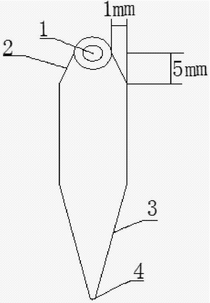
图1是本发明实施例移液管的结构示意图; Fig. 1 is the structural representation of pipette of the embodiment of the present invention;
图2是本发明实施例移液管的另一结构示意图。 Fig. 2 is another structural schematic diagram of the pipette of the embodiment of the present invention. the
其中:1、端口;2、连接端;3、尖嘴;4、移液口;5、凸沿。 Among them: 1. port; 2. connecting end; 3. pointed mouth; 4. pipetting port; 5. convex edge. the
具体实施方式 Detailed ways
下面结合附图和较佳的实施例对本发明作进一步说明。 The present invention will be further described below in conjunction with the accompanying drawings and preferred embodiments. the
本发明公开一种移液管,如图1和2所示,包括一端有尖嘴3的移液口4和另一端用于与橡皮管套接的连接端2,所述连接端2的外径向 端口1方向逐渐缩小。
The invention discloses a pipette, as shown in Figures 1 and 2, comprising a pipetting port 4 with a sharp mouth 3 at one end and a connecting
本发明由于移液管与医用橡皮管套接的连接端2的外径向其端口1方向逐渐缩小,从而就方便橡皮管套接在移液管的连接端2;一般橡皮管的内径略小于连接端2的最大外径,这样橡皮管套接在连接端2上后连接紧密,不易脱落和漏气。而且连接端2的端口1处外径较小方便橡皮管套接,从而就不会出现弄伤操作者手指的现象。
In the present invention, since the outer diameter of the connecting
如图1所示,连接端2的外径向端口1方向逐渐缩小形成锥形结构,具体的呈圆锥结构,即连接端2的横截面为圆环形结构,这样设置就进一步方便橡皮管套接在连接端2上,而且使套接固定后不易漏气,方便使用。本实施例连接端2的端口1的外径略小于橡皮管的内径,且橡皮管的内径略小于连接端2的最大外径,从而不仅方便橡皮管套接在连接端2,而且使套接固定后连接紧密,不易漏气。
As shown in Figure 1, the outer radial direction of the connecting
在本实施例中,连接端2的端口1边沿外侧壁设有倒圆角,从而进一步方便橡皮管套接在连接端2上,且操作者在将橡皮管套接在移液管的连接端2上时就不会因为端口1的棱角而受到伤害。
In this embodiment, the outer side wall of port 1 of the connecting
作为本实施例的进一步改进,如图2所示,连接端2外表面设有至少一圈的环形凸沿5,环形凸沿5的最大外径小于连接端2的最大外径,从而增加连接端2和橡皮管套接的紧密性,防止漏气。环形凸沿5可设置为一个,也可设置两个甚至更多进行间隔布置。且环形凸沿5的竖截面为弧形结构,即环形凸沿5的表面为圆弧面结构,减少摩擦力,从而便于橡皮管套接在连接端2上。
As a further improvement of this embodiment, as shown in Figure 2, the outer surface of the connecting
本实施例连接端2的垂直高度为2至8毫米,如图1至2所示,优选的方案为连接端2的高度为5毫米,这是设置连接端2的最佳高度,方便橡皮管套接在连接端2上,且使连接紧密。对应的,连接端2的最大外径和最小外径之差为1毫米,即连接端2的最大外半径和最小外半径之差为1毫米。
The vertical height of the
以上内容是结合具体的优选实施方式对本发明所作的进一步详细说明,不能认定本发明的具体实施只局限于这些说明。对于本发明所属技术领域的普通技术人员来说,在不脱离本发明构思的前提 下,还可以做出若干简单推演或替换,都应当视为属于本发明的保护范围。 The above content is a further detailed description of the present invention in conjunction with specific preferred embodiments, and it cannot be assumed that the specific implementation of the present invention is limited to these descriptions. For those of ordinary skill in the technical field of the present invention, without departing from the concept of the present invention, some simple deduction or replacement can also be made, which should be regarded as belonging to the protection scope of the present invention. the
Claims (9)
Priority Applications (2)
| Application Number | Priority Date | Filing Date | Title |
|---|---|---|---|
| CN201310557310.9A CN103566989B (en) | 2013-11-08 | 2013-11-08 | A kind of pipette |
| PCT/CN2013/086941 WO2015066931A1 (en) | 2013-11-08 | 2013-11-12 | Pipette |
Applications Claiming Priority (1)
| Application Number | Priority Date | Filing Date | Title |
|---|---|---|---|
| CN201310557310.9A CN103566989B (en) | 2013-11-08 | 2013-11-08 | A kind of pipette |
Publications (2)
| Publication Number | Publication Date |
|---|---|
| CN103566989A true CN103566989A (en) | 2014-02-12 |
| CN103566989B CN103566989B (en) | 2016-01-20 |
Family
ID=50040212
Family Applications (1)
| Application Number | Title | Priority Date | Filing Date |
|---|---|---|---|
| CN201310557310.9A Active CN103566989B (en) | 2013-11-08 | 2013-11-08 | A kind of pipette |
Country Status (2)
| Country | Link |
|---|---|
| CN (1) | CN103566989B (en) |
| WO (1) | WO2015066931A1 (en) |
Citations (7)
| Publication number | Priority date | Publication date | Assignee | Title |
|---|---|---|---|---|
| EP1065001A1 (en) * | 1998-03-19 | 2001-01-03 | Precision System Science Co., Ltd. | Apparatus for integrating processing of magnetic particles, and method of controlling the same |
| CN201186218Y (en) * | 2008-03-18 | 2009-01-28 | 何茂婧 | Liquid transferring tube with switch device |
| CN201565310U (en) * | 2009-12-02 | 2010-09-01 | 昆明理工大学 | Pipette |
| CN202158295U (en) * | 2011-07-05 | 2012-03-07 | 安徽中鼎金亚汽车管件制造有限公司 | Assembly connection structure |
| CN102847569A (en) * | 2012-08-29 | 2013-01-02 | 浙江硕华医用塑料有限公司 | Disposable pipette |
| WO2013134271A1 (en) * | 2012-03-06 | 2013-09-12 | Porex Corporation | Sintered porous plastic plug for serological pipette |
| CN203598833U (en) * | 2013-11-08 | 2014-05-21 | 邢皓宇 | Pipette |
Family Cites Families (1)
| Publication number | Priority date | Publication date | Assignee | Title |
|---|---|---|---|---|
| TW200425889A (en) * | 2004-07-08 | 2004-12-01 | Jenn-Hae Luo | Sealed dropper loaded with medicine solution |
-
2013
- 2013-11-08 CN CN201310557310.9A patent/CN103566989B/en active Active
- 2013-11-12 WO PCT/CN2013/086941 patent/WO2015066931A1/en not_active Ceased
Patent Citations (7)
| Publication number | Priority date | Publication date | Assignee | Title |
|---|---|---|---|---|
| EP1065001A1 (en) * | 1998-03-19 | 2001-01-03 | Precision System Science Co., Ltd. | Apparatus for integrating processing of magnetic particles, and method of controlling the same |
| CN201186218Y (en) * | 2008-03-18 | 2009-01-28 | 何茂婧 | Liquid transferring tube with switch device |
| CN201565310U (en) * | 2009-12-02 | 2010-09-01 | 昆明理工大学 | Pipette |
| CN202158295U (en) * | 2011-07-05 | 2012-03-07 | 安徽中鼎金亚汽车管件制造有限公司 | Assembly connection structure |
| WO2013134271A1 (en) * | 2012-03-06 | 2013-09-12 | Porex Corporation | Sintered porous plastic plug for serological pipette |
| CN102847569A (en) * | 2012-08-29 | 2013-01-02 | 浙江硕华医用塑料有限公司 | Disposable pipette |
| CN203598833U (en) * | 2013-11-08 | 2014-05-21 | 邢皓宇 | Pipette |
Also Published As
| Publication number | Publication date |
|---|---|
| CN103566989B (en) | 2016-01-20 |
| WO2015066931A1 (en) | 2015-05-14 |
Similar Documents
| Publication | Publication Date | Title |
|---|---|---|
| CN103566989B (en) | A kind of pipette | |
| CN210560431U (en) | Simple embryo suction device | |
| CN203598833U (en) | Pipette | |
| CN221141170U (en) | Ampoule opening device | |
| CN205435779U (en) | Anti -pollution liquid -transfering gun head of anticreep | |
| CN205741021U (en) | A kind of centrifugal tubular type sterile culture flask | |
| CN202236873U (en) | Tapered joint of drainage tube | |
| CN204192629U (en) | Blood-taking device | |
| CN211436245U (en) | Anti-pumpback pipette head | |
| CN206229377U (en) | Liquid-transfering gun | |
| CN207562014U (en) | It is a kind of to pick ovum needle and embryo operation needle for cattle and sheep embryo transfer | |
| CN207575291U (en) | A kind of tool for assisting sheep embryo transfer | |
| CN209220358U (en) | Operating hole introducer | |
| CN204490878U (en) | For the connector bend dropping tube of cell cultures | |
| CN205313577U (en) | Aseptic cell culture bottle | |
| CN205870331U (en) | Holder | |
| CN216394866U (en) | Connecting structure for sputum suction device | |
| CN208032606U (en) | A kind of combined type liquid transfer gun head | |
| CN204724187U (en) | A kind of natural sciences chemistry dropper | |
| CN206391275U (en) | Anti-stabbing transfusion device | |
| CN208018634U (en) | A kind of rubber head dropper | |
| CN204323928U (en) | There is Bottle cap structure and the cell culture bags of sealing and anti-pollution function | |
| CN211213042U (en) | Easy-to-clean silicone straws | |
| CN202075287U (en) | Disposable lengthening conductive sample application tip | |
| CN205361383U (en) | Anti -pollution pipette head |
Legal Events
| Date | Code | Title | Description |
|---|---|---|---|
| C06 | Publication | ||
| PB01 | Publication | ||
| SE01 | Entry into force of request for substantive examination | ||
| SE01 | Entry into force of request for substantive examination | ||
| C14 | Grant of patent or utility model | ||
| GR01 | Patent grant | ||
| CB03 | Change of inventor or designer information | ||
| CB03 | Change of inventor or designer information |
Inventor after: Du Meng Inventor before: Shang Zhi |
|
| TR01 | Transfer of patent right | ||
| TR01 | Transfer of patent right |
Effective date of registration: 20170814 Address after: Zhuang town of Shandong County in Ningjin Province Zhang Hou Zheng Village No. 260 Patentee after: Du Meng Address before: 518000 Shenzhen City, Futian District province Hongling building,, 1 25B Co-patentee before: Shang Zhi Patentee before: Xing Haoyu |
|
| TR01 | Transfer of patent right | ||
| TR01 | Transfer of patent right |
Effective date of registration: 20180316 Address after: 102600, No. 3, building 2, building 4, Paradise Road, Beijing, Daxing District, 1, unit 317 Patentee after: BEIJING ZHITOUJIA INTELLECTUAL PROPERTY OPERATION CO.,LTD. Address before: Zhuang town of Shandong County in Ningjin Province Zhang Hou Zheng Village No. 260 Patentee before: Du Meng |
|
| TR01 | Transfer of patent right | ||
| TR01 | Transfer of patent right |
Effective date of registration: 20181219 Address after: 225300 room 104, Pearl Road, Yongan Town, Yongan, Taizhou, Jiangsu Patentee after: Gai Nannan Address before: 102600 3 floor, 2 building, No. 4 Daxing District Garden Road, Beijing, 1 unit 317 Patentee before: BEIJING ZHITOUJIA INTELLECTUAL PROPERTY OPERATION CO.,LTD. |
|
| TR01 | Transfer of patent right |
Effective date of registration: 20191202 Address after: 314000 Xinxing community, Wanghai street, Haiyan County, Jiaxing City, Zhejiang Province Patentee after: JIAXING TONGDA MACHINERY Co.,Ltd. Address before: 225300 Room 104, 108 Pearl Avenue, Yonganzhou Town, Gaogang District, Taizhou City, Jiangsu Province Patentee before: Gai Nannan |
|
| TR01 | Transfer of patent right | ||
| TR01 | Transfer of patent right | ||
| TR01 | Transfer of patent right |
Effective date of registration: 20211014 Address after: No. 115, Xuzhuang, linbu Town, juancheng County, Heze City, Shandong Province Patentee after: Shandong juancheng Guangming Instrument Co.,Ltd. Address before: 314000 Xinxing community, Wanghai street, Haiyan County, Jiaxing City, Zhejiang Province Patentee before: JIAXING TONGDA MACHINERY Co.,Ltd. |
|
| TR01 | Transfer of patent right | ||
| TR01 | Transfer of patent right |
Effective date of registration: 20240828 Address after: 163000 commercial service building 1-016, No. 14, Zhongqiao Road, Sartu District, Daqing City, Heilongjiang Province Patentee after: Daqing shengjiyuan Technology Co.,Ltd. Country or region after: China Address before: No. 115, Xuzhuang, linbu Town, juancheng County, Heze City, Shandong Province Patentee before: Shandong juancheng Guangming Instrument Co.,Ltd. Country or region before: China |
|
| TR01 | Transfer of patent right | ||
| TR01 | Transfer of patent right |
Effective date of registration: 20260327 Address after: 271000 Shandong Province Taian City Ningyang County Huafeng Town Xigu Cheng Village 257 Hao Patentee after: Shandong essent New Energy Development Co.,Ltd. Country or region after: China Address before: 163000 commercial service building 1-016, No. 14, Zhongqiao Road, Sartu District, Daqing City, Heilongjiang Province Patentee before: Daqing shengjiyuan Technology Co.,Ltd. Country or region before: China |
|
| CP03 | Change of name, title or address |
Address after: 271000 Shandong Province Taian City Ningyang County Huafeng Town Xigu Cheng Village 257 Hao Patentee after: Shandong Aisen Te Technology Development Co., Ltd. Country or region after: China Address before: 271000 Shandong Province Taian City Ningyang County Huafeng Town Xigu Cheng Village 257 Hao Patentee before: Shandong essent New Energy Development Co.,Ltd. Country or region before: China |
|
| CP03 | Change of name, title or address |