CN103523681A - Dual-beam movable container loading bridge - Google Patents
Dual-beam movable container loading bridge Download PDFInfo
- Publication number
- CN103523681A CN103523681A CN201310519330.7A CN201310519330A CN103523681A CN 103523681 A CN103523681 A CN 103523681A CN 201310519330 A CN201310519330 A CN 201310519330A CN 103523681 A CN103523681 A CN 103523681A
- Authority
- CN
- China
- Prior art keywords
- dolly
- large beam
- doorframe
- door frame
- rear door
- Prior art date
- Legal status (The legal status is an assumption and is not a legal conclusion. Google has not performed a legal analysis and makes no representation as to the accuracy of the status listed.)
- Granted
Links
- 230000007246 mechanism Effects 0.000 claims abstract description 19
- 229910000831 Steel Inorganic materials 0.000 claims description 3
- 239000010959 steel Substances 0.000 claims description 3
- 230000008901 benefit Effects 0.000 abstract description 6
- 238000012423 maintenance Methods 0.000 description 2
- 238000004519 manufacturing process Methods 0.000 description 2
- 238000004378 air conditioning Methods 0.000 description 1
- 230000015572 biosynthetic process Effects 0.000 description 1
- 230000002860 competitive effect Effects 0.000 description 1
- 230000007423 decrease Effects 0.000 description 1
- 238000006073 displacement reaction Methods 0.000 description 1
- 230000000694 effects Effects 0.000 description 1
- 238000005516 engineering process Methods 0.000 description 1
- 230000004048 modification Effects 0.000 description 1
- 238000012986 modification Methods 0.000 description 1
Images

Landscapes
- Load-Engaging Elements For Cranes (AREA)
Abstract
The invention relates to a dual-beam movable container loading bridge. An upper beam is fixedly connected with the tops of a front doorframe and a rear doorframe, the lower plane of the upper beam is provided with rails, a first upper dolly and a second upper dolly are respectively installed on the front part and the rear part of the upper beam, and the lower parts of the front doorframe and the rear doorframe are respectively connected with a running gear; a lower beam is equipped with adjustable longitudinal and transverse rollers and realizes up-and-down motion under the driving of a driving mechanism and two sets of pulley blocks; the first upper dolly and the second upper dolly are respectively mounted on the rails located at the front part and the rear part of the upper beam and respectively equipped with a lifting mechanism and a container spreader; a lower dolly is mounted on a rail of the lower beam and is equipped with an operating mechanism; and a lower beam moving mechanism and the pulley blocks are mounted on the top of a crossbeam between the front doorframe and the rear doorframe. The dual-beam movable container loading bridge is applicable to an ultra-large container carrier and has the advantages of a simple structure, definite stress, light weight, high efficiency, capacity of realizing loading and unloading of three containers in a working cycle, conservation of investment and energy and substantial improvement of operation benefits.
Description
Technical field
The present invention relates to the containerable cargo loading and unloading operation system on box ship, be specifically related to a kind of bank freight container is filled to box ship or contrary, the freight container being about on box ship is discharged to the container loading bridge on bank rapidly by continuous working.
Background technology
Conventionally, a large amount of freight containers by general shore container crane by container handling to box ship.It is low that this class container loading bridge moves repetition, efficiency in operation, and handling equipment complex structure, huge, involves great expense, and installs complicatedly, and harbour wheel load is large, so that the fabrication cost of harbour is high.
In view of this, the equipment of seeking a kind of novel alternative shore container crane becomes pursuing a goal of these those skilled in the art.
Summary of the invention
Task of the present invention is to provide a kind of pair of Beam mobile container handling bridge, it is a kind of container crane of continuous working mode, solved original conventional version shore container crane efficiency low, involve great expense, harbour load is large, investment large, energy resource consumption is large drawback.
Technical solution of the present invention is as follows:
A Beam mobile container handling bridge, it comprises on large Beam, lower large Beam, front doorframe, rear door frame, first dolly, lower dolly, traveling gear ,Xia great Beam travel mechanism, assembly pulley and electric power supply control system on dolly, second;
The top of described large Beam and front doorframe and rear door frame is affixed, and upper large Beam lower plane is provided with track, and dolly is arranged on the front portion of large Beam on first, and dolly is arranged on the rear portion of large Beam on second, and the bottom of front doorframe and rear door frame is connected respectively traveling gear;
Described lower large Beam is arranged on the below of large Beam, and adjustable longitudinal and transverse-roller is housed on lower large Beam, and lower large Beam drives realization to move up and down by the driver train and the two groups of assembly pulleys that are positioned at front doorframe and rear door frame top;
On described first, dolly is arranged on the track of large Beam front portion, and dolly is equipped with lifting mechanism and container spreader on first;
On described second, dolly is arranged on the track at large Beam rear portion, and dolly is equipped with lifting mechanism and container spreader on second;
Described lower dolly is arranged on the track of lower large Beam, and lower dolly is equipped with operating unit, the freight container of dolly on first can be transported and be displaced to little truck position on second, or the freight container of dolly on second is transported and is displaced to little truck position on first;
Described Xia great Beam travel mechanism and assembly pulley are arranged on the horizontal Beam top of front doorframe and rear door frame.
On three faces of described front doorframe box-type section, raceway is housed, to support the motion of lower large Beam shifting roller.
On three faces of described rear door frame box-type section, raceway is housed, to support the motion of lower large Beam shifting roller.
Described traveling gear is comprised of chassis combination driver train.
Described Xia great Beam travel mechanism adopts Steel rope drive, and breaking rope protecting system and balance synchro system are housed.
Described electric power supply control system comprises cable drum control, PLC control, fender guard, interlocked control and drive control part.
The present invention, owing to having adopted above technical scheme, makes it compared with prior art, and of the present invention pair of Beam mobile container handling bridge has following advantages:
1, two Beam mobile container handling bridges three freight containers of operation simultaneously in a working cycle, so this type can be raised the efficiency 2.5~3 times than traditional type.
2, because two Beam mobile container handling bridges are simple for structure, stressed clear and definite, good from heavy and light, anufacturability, can make outreach significantly improve, do not need luffing mechanism, therefore applicable to operation oversized container ship (1.8 ten thousand casees 10 ton box ships) simultaneously.
3, a common van container berth (as the box ship of 5 tons, 6~7,000 casees), need five conventional shore container crane operations simultaneously, if adopt two Beam mobile container handling bridges, only need to install two just can reach same capacity rating to three.This has not only reduced equipment investment and maintenance cost, has reduced harbour bearing load simultaneously, the harbour Hydraulic Engineering cost that therefore can greatly decline, thus saving energy resource consumption, the operating benefit ,Shi enterprise of greatly improving harbour is more competitive.
Of the present invention pair of Beam mobile container handling bridge is applicable to oversized container ship, simple in structure, stressed clear and definite, lightweight, efficiency is high, realizes the loading and unloading operation of three freight containers in a working cycle, saves investment, safe and reliable, save the energy, greatly improved operating benefit.The container handling device of applying of the present invention pair of Beam mobile container handling bridge ,Dui China and the world can reach the effect of update.
Accompanying drawing explanation
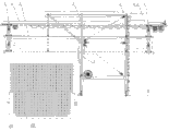
Fig. 1 is the front view of a kind of pair of Beam mobile container handling bridge of the present invention.
Fig. 2 is by the right elevation of container loading bridge shown in Fig. 1.
Reference numeral:
1 is upper large Beam, and 2 is lower large Beam, and 3 is front doorframe, and 4 is rear door frame, and 5 is dolly on first, and 6 is dolly on second, and 7 is lower dolly, and 8 is traveling gear, and 9 is assembly pulley, and 10 is machine house and electrical house, and 11 is electric power supply control system, and 12 is 1.8 ten thousand casees box ships.
The specific embodiment
Below in conjunction with drawings and Examples, the present invention is elaborated.
Referring to Fig. 1 and Fig. 2, mainly by large Beam, (be divided on upper large Beam 1, lower large Beam 2, front doorframe 3, rear door frame 4, first dolly 6, lower dolly 7, traveling gear 8 ,Xia great Beam travel mechanisms, assembly pulley 9, electric power supply control system 11 and machine house and electrical house 10 on dolly 5, second forms a kind of pair of Beam mobile container handling bridge of the present invention.
Upper large Beam 1 is affixed with the top of front doorframe 3 and rear door frame 4.Upper large Beam 1 lower plane attachment rail.On first, dolly 5 is arranged on the front portion of large Beam 1, and dolly 6 is arranged on the rear portion of large Beam 1 on second.The bottom of front doorframe 3 and rear door frame 4 is connected respectively traveling gear 8.
Lower large Beam 2 is arranged on the below of large Beam 1.Adjustable longitudinal and transverse-roller is housed on lower large Beam 2.Lower large Beam 2 is driven by the driver train and the two groups of assembly pulleys 9 that are positioned at front doorframe 3 and rear door frame 4 tops, and realization moves up and down, and reaches the best get case, vanning position with adjusting position.
On first, dolly 5 is arranged on the track of large Beam 1 front portion.On first, the radical function of dolly 5 is to utilize the container spreader that has being contained on dolly to hoist and drop set vanning, and it is specifically designed to the freight container on loading, unloading box ship, and the function with transverse shifting is in order to alignment box position.In Fig. 1, the lower left corner is 1.8 ten thousand casees box ships 12.
On second, dolly 6 is arranged on the track at large Beam 1 rear portion.On second, the radical function of dolly 6 is to utilize the container spreader be contained on dolly to hoist and drop set vanning, and it is specifically designed to the freight container on loading, unloading container truck, or for the operation of container depot; The function simultaneously with transverse shifting, in order to alignment box position.
Lower dolly 7 is arranged on the track of lower large Beam 2.The groundwork mechanism of lower dolly 7 is operating units, is the freight container of dolly on first 5 is transported and is displaced to dolly 6 positions on second, or contrary, the freight container of dolly on second 6 is transported and is displaced to dolly 5 positions on first.
Its duty of three each row of dolly, circulation, organic, work in an orderly manner, lower large Beam 2 can do upper and lower displacement along forward and backward doorframe, lower large Beam 2 moves up and down and regulates the best to get case, vanning position, works in coordination and reaches largest production efficiency.
Front doorframe 3 adopts box-structure, and front doorframe 3 tops are connected with upper large Beam 1, on three faces of box-type section, raceway are installed, in order to support the motion of lower large Beam 2 shifting rollers.Front doorframe 3 bottoms are connected with traveling gear.
Rear door frame 4 adopts box-structure, and rear door frame 4 tops are connected with upper large Beam 1, on three faces of box-type section, raceway are installed, in order to support the motion of lower large Beam 2 shifting rollers.Rear door frame 4 bottoms are connected with traveling gear.
Front doorframe 3 tops, can install machinery room and electrical house 10 on horizontal Beam by horizontal Beam and the rear door frame 4 formation framed structure that is fixedly connected.Machine house and electrical house 10 are fixed on the top of doorframe, for ease of maintenance, are provided with lifting crane, air-conditioning etc.
Traveling gear 8 is comprised of chassis combination driver train, in the time of in working order, realizes and moving to adapt to the work of suspender, has various safety devices to guarantee the safety of complete machine when off working state (strong wind, typhoon).
Xia great Beam travel mechanism and assembly pulley 9 are arranged on the horizontal Beam top of front doorframe 3 and rear door frame 4, and assembly pulley 9 is also arranged on the top of lower large Beam 2, for driving moving up and down of lower large Beam 2.Xia great Beam travel mechanism adopts Steel rope drive, and it is simple in structure, safe, reliable, and breaking rope protecting system and balance synchro system are housed.
Electric power supply control system 11 is mainly grouped into by cable drum control, PLC control, fender guard, interlocked control and drive control part.Electric control system is comprised of control panel, PLC, frequency converter, the MSN system of each driver train, makes three dolly harmonious orderlies and works, and reaches safe, reliable, efficient object.
In sum, of the present invention pair of Beam mobile container handling bridge is applicable to oversized container ship, simple in structure, stressed clear and definite, lightweight, efficiency is high, in a working cycle, realize the loading and unloading operation of three freight containers, save investment, safe and reliable, save the energy, greatly improved operating benefit.
Certainly, those skilled in the art in the art will be appreciated that, above-described embodiment is only for the present invention is described, and not as limitation of the invention, as long as within the scope of connotation of the present invention, the variation of above-described embodiment, modification etc. all will be dropped in the scope of the claims in the present invention.
Claims (6)
1. two Beam mobile container handling bridges, is characterized in that: it comprises on large Beam (1), lower large Beam (2), front doorframe (3), rear door frame (4), first dolly (6), lower dolly (7), traveling gear (8) ,Xia great Beam travel mechanism, assembly pulley (9) and electric power supply control system (11) on dolly (5), second;
Described large Beam (1) is affixed with the top of front doorframe (3) and rear door frame (4), upper large Beam (1) lower plane is provided with track, dolly on first (5) is arranged on the front portion of large Beam (1), dolly on second (6) is arranged on the rear portion of large Beam (1), and the bottom of front doorframe (3) and rear door frame (4) is connected respectively traveling gear (8);
Described lower large Beam (2) is arranged on the below of large Beam (1), adjustable longitudinal and transverse-roller is housed on lower large Beam (2), and lower large Beam (2) drives realization to move up and down by the driver train and the two groups of assembly pulleys (9) that are positioned at front doorframe (3) and rear door frame (4) top;
Dolly on described first (5) is arranged on the anterior track of large Beam (1), and dolly (5) is equipped with lifting mechanism and container spreader on first;
Dolly on described second (6) is arranged on the track at large Beam (1) rear portion, and dolly (6) is equipped with lifting mechanism and container spreader on second;
Described lower dolly (7) is arranged on the track of lower large Beam (2), lower dolly (7) is equipped with operating unit, the freight container of dolly on first (5) can be transported and be displaced to dolly on second (6) position, or the freight container of dolly on second (6) is transported and is displaced to dolly on first (5) position;
Described Xia great Beam travel mechanism and assembly pulley (9) are arranged on the horizontal Beam top of front doorframe (3) and rear door frame (4).
2. according to claim 1 pair of Beam mobile container handling bridge, is characterized in that: on three faces of described front doorframe (3) box-type section, raceway is housed, to support the motion of lower large Beam (2) shifting roller.
3. according to claim 1 pair of Beam mobile container handling bridge, is characterized in that: on three faces of described rear door frame (4) box-type section, raceway is housed, to support the motion of lower large Beam (2) shifting roller.
4. according to claim 1 pair of Beam mobile container handling bridge, is characterized in that: described traveling gear (8) is comprised of chassis combination driver train.
5. according to claim 1 pair of Beam mobile container handling bridge, is characterized in that: described Xia great Beam travel mechanism adopts Steel rope drive, and breaking rope protecting system and balance synchro system are housed.
6. according to claim 1 pair of Beam mobile container handling bridge, is characterized in that: described electric power supply control system (11) comprises cable drum control, PLC control, fender guard, interlocked control and drive control part.
Priority Applications (1)
| Application Number | Priority Date | Filing Date | Title |
|---|---|---|---|
| CN201310519330.7A CN103523681B (en) | 2013-10-29 | 2013-10-29 | Two Beam mobile container handling bridge |
Applications Claiming Priority (1)
| Application Number | Priority Date | Filing Date | Title |
|---|---|---|---|
| CN201310519330.7A CN103523681B (en) | 2013-10-29 | 2013-10-29 | Two Beam mobile container handling bridge |
Publications (2)
| Publication Number | Publication Date |
|---|---|
| CN103523681A true CN103523681A (en) | 2014-01-22 |
| CN103523681B CN103523681B (en) | 2015-09-30 |
Family
ID=49926112
Family Applications (1)
| Application Number | Title | Priority Date | Filing Date |
|---|---|---|---|
| CN201310519330.7A Expired - Fee Related CN103523681B (en) | 2013-10-29 | 2013-10-29 | Two Beam mobile container handling bridge |
Country Status (1)
| Country | Link |
|---|---|
| CN (1) | CN103523681B (en) |
Cited By (3)
| Publication number | Priority date | Publication date | Assignee | Title |
|---|---|---|---|---|
| CN105460645A (en) * | 2016-01-29 | 2016-04-06 | 温岭市盛开物流设备科技有限公司 | House type bag bundling and shipping device |
| CN108689308A (en) * | 2018-07-17 | 2018-10-23 | 东台市富康机械有限公司 | Gantry crane with floating body bearing |
| CN111056496A (en) * | 2019-12-20 | 2020-04-24 | 高湘 | A bridge-type container reach stacker |
Citations (8)
| Publication number | Priority date | Publication date | Assignee | Title |
|---|---|---|---|---|
| US3630390A (en) * | 1969-02-07 | 1971-12-28 | Hans Tax | Container-loading crane arrangement |
| DE4439740C1 (en) * | 1994-10-28 | 1996-05-09 | Noell Gmbh | Container terminal with integrated fully automatic container transport system |
| DE19740513A1 (en) * | 1997-09-15 | 1999-03-18 | Tax Ingenieurgesellschaft Mbh | Container transfer crane |
| KR20030006012A (en) * | 2001-07-11 | 2003-01-23 | 한만엽 | Gantry crane having circulating spreader |
| CN1764593A (en) * | 2003-03-22 | 2006-04-26 | 诺尔起重系统有限公司 | Multi-trolley container crane |
| CN1785786A (en) * | 2004-12-08 | 2006-06-14 | 上海振华港口机械(集团)股份有限公司 | Rise and fall crossbeam type crane for container |
| CN201092515Y (en) * | 2007-01-23 | 2008-07-30 | 武汉理工大学 | New high-efficiency container loading and unloading bridge |
| CN203529778U (en) * | 2013-10-29 | 2014-04-09 | 上海公茂起重设备有限公司 | Double-beam mobile loading bridge for container |
-
2013
- 2013-10-29 CN CN201310519330.7A patent/CN103523681B/en not_active Expired - Fee Related
Patent Citations (8)
| Publication number | Priority date | Publication date | Assignee | Title |
|---|---|---|---|---|
| US3630390A (en) * | 1969-02-07 | 1971-12-28 | Hans Tax | Container-loading crane arrangement |
| DE4439740C1 (en) * | 1994-10-28 | 1996-05-09 | Noell Gmbh | Container terminal with integrated fully automatic container transport system |
| DE19740513A1 (en) * | 1997-09-15 | 1999-03-18 | Tax Ingenieurgesellschaft Mbh | Container transfer crane |
| KR20030006012A (en) * | 2001-07-11 | 2003-01-23 | 한만엽 | Gantry crane having circulating spreader |
| CN1764593A (en) * | 2003-03-22 | 2006-04-26 | 诺尔起重系统有限公司 | Multi-trolley container crane |
| CN1785786A (en) * | 2004-12-08 | 2006-06-14 | 上海振华港口机械(集团)股份有限公司 | Rise and fall crossbeam type crane for container |
| CN201092515Y (en) * | 2007-01-23 | 2008-07-30 | 武汉理工大学 | New high-efficiency container loading and unloading bridge |
| CN203529778U (en) * | 2013-10-29 | 2014-04-09 | 上海公茂起重设备有限公司 | Double-beam mobile loading bridge for container |
Cited By (4)
| Publication number | Priority date | Publication date | Assignee | Title |
|---|---|---|---|---|
| CN105460645A (en) * | 2016-01-29 | 2016-04-06 | 温岭市盛开物流设备科技有限公司 | House type bag bundling and shipping device |
| CN105460645B (en) * | 2016-01-29 | 2018-05-22 | 温岭市盛开物流设备科技有限公司 | A kind of room formula bag package bundle fills shipment equipment |
| CN108689308A (en) * | 2018-07-17 | 2018-10-23 | 东台市富康机械有限公司 | Gantry crane with floating body bearing |
| CN111056496A (en) * | 2019-12-20 | 2020-04-24 | 高湘 | A bridge-type container reach stacker |
Also Published As
| Publication number | Publication date |
|---|---|
| CN103523681B (en) | 2015-09-30 |
Similar Documents
| Publication | Publication Date | Title |
|---|---|---|
| CN206427933U (en) | A kind of bridge crane | |
| CN102556854B (en) | Mine hydraulic hoisting traveling crane | |
| CN102616666A (en) | Semi-traction dolly type light-weight portal crane | |
| CN110817491B (en) | Intelligent coal leveling device for coal loading | |
| CN204588496U (en) | A kind of three degree of freedom purlin car being applicable to small space | |
| CN201092515Y (en) | New high-efficiency container loading and unloading bridge | |
| CN203624874U (en) | Special crane for transporting fan blade | |
| CN104495585A (en) | Intelligent vertical traction machine | |
| CN103523681B (en) | Two Beam mobile container handling bridge | |
| CN206107398U (en) | Scrapped car disassembly line | |
| CN203638615U (en) | Cross-rail transport assembly vehicle | |
| CN203359556U (en) | Barrel dumping vehicle improved on basis of electric fork truck | |
| CN204778506U (en) | Container crane of two main dollies | |
| CN204778459U (en) | Double small car container bank bridge | |
| CN203529778U (en) | Double-beam mobile loading bridge for container | |
| CN202429920U (en) | Multi-trolley and double-girder gantry crane | |
| CN207361622U (en) | Logistic storage piler | |
| CN205933012U (en) | Multi -functional jack -up straddle carrier | |
| CN104591002A (en) | Low-clearance double-beam bridge type crane | |
| CN208071104U (en) | A kind of hoisting steel plate device | |
| CN201587815U (en) | Double-main-beam multi-point hoist gantry | |
| CN105293278A (en) | Electric block type double-rail and single-main-beam crane | |
| CN205472287U (en) | Suspension type single -beam crane | |
| CN205114887U (en) | Hand propelled removes portal frame | |
| CN105274914B (en) | A kind of magnetic floats section of track movement gantry crane |
Legal Events
| Date | Code | Title | Description |
|---|---|---|---|
| C06 | Publication | ||
| PB01 | Publication | ||
| SE01 | Entry into force of request for substantive examination | ||
| SE01 | Entry into force of request for substantive examination | ||
| C14 | Grant of patent or utility model | ||
| GR01 | Patent grant | ||
| CF01 | Termination of patent right due to non-payment of annual fee | ||
| CF01 | Termination of patent right due to non-payment of annual fee |
Granted publication date: 20150930 Termination date: 20181029 |