CN103490486A - Wireless charging device of portable electronic equipment - Google Patents
Wireless charging device of portable electronic equipment Download PDFInfo
- Publication number
- CN103490486A CN103490486A CN201310399324.2A CN201310399324A CN103490486A CN 103490486 A CN103490486 A CN 103490486A CN 201310399324 A CN201310399324 A CN 201310399324A CN 103490486 A CN103490486 A CN 103490486A
- Authority
- CN
- China
- Prior art keywords
- module
- energy
- wireless charging
- charging device
- portable electric
- Prior art date
- Legal status (The legal status is an assumption and is not a legal conclusion. Google has not performed a legal analysis and makes no representation as to the accuracy of the status listed.)
- Pending
Links
Images


Abstract
The invention discloses a wireless charging device of portable electronic equipment. The wireless charging device of the portable electronic equipment comprises an energy emitting device and an energy receiving device. The energy emitting device comprises a power supply module, a direct-current voltage-reduction module, a main control module, a direct current-alternating current converting and driving module, an energy emitting coil, a signal demodulation module, a temperature detecting module, an indicator lamp module and a buzzer module. The energy receiving module comprises a wireless charging control module and a wireless charging energy receiving coil. The energy emitting device is manufactured to be an independent wireless charging device body, the energy receiving device is arranged on the corresponding portable electronic equipment, the portable electronic equipment is attached to the wireless charging device body, and wireless charging can be conducted on the portable electronic equipment simply through the energy emitting device and the energy receiving device. The wireless charging device can meet Qi standards, and the wireless charging device can be used for charging any portable electronic equipment as long as the energy receiving device is installed.
Description
Technical field
The present invention relates to the electric equipment products technical field, specifically, is aly can carry out the charging device of wireless charging for portable electric appts, and the portable electric appts of every applicable DC power supply all can be included range of application of the present invention in.
Background technology
The development of electronic technology makes various electronic products extensively go on the market, and is very easy to people's live and work.But the electronic product in use problem of maximum is exactly the problem of power consumption.Therefore, many electronic products are typically equipped with charger, at present, are mainly wired chargers, and the charger of the product of different model or the configuration of different manufacturers product is inconsistent toward contact, can not be general.The main deficiency of existing charging device is: (1) one machine one fills, and has the wasting of resources; (2) hard contact contact, the hidden danger that has electric leakage and get an electric shock are arranged; (3) open charging inlet, easily be subject to the impact of dust and wet gas; (4) need the manual intervention charging process, the user experiences poor.
The wireless charging technology is the new technology occurred in recent years.Studying relevant wireless charging product according to each enterprise of this know-why.From the existing disclosed content of document, is directly portable electric appts at present, the device that especially uses the portable electric appts of DC power supply to carry out wireless charging does not almost have.Portable electric appts, for the feature of outstanding " portable ", generally can not done very greatly by the volume of product, corresponding, and the volume of battery part also can be limited, and therefore, the flying power of its electric energy receives everybody concern always.At present, portable electric appts is widely used is battery or button cell, and as do not charged in time, the flying power of its electric energy just has problem, and this can have influence on the use of portable electric appts.
Summary of the invention
The object of the invention is to address the above problem, a kind of portable electric appts wireless charging device is provided, this wireless charging device has saved charging inlet, as long as the energy receiving system of wireless charging is set on portable electric appts, just can carry out wireless charging for portable electric appts easily, solve existing portable electric appts and drag the possible problem of line charging modes, making people utilize " fragment " time to charge easily becomes possibility; Described wireless charging device can carry out wireless charging to the portable electric appts of any use DC power supply.
For achieving the above object, the present invention has adopted following technical scheme.
A kind of portable electric appts wireless charging device, comprise energy emitter and energy receiving system, it is characterized in that, described energy emitter comprises supply module, DC decompression module, main control module, DC-AC conversion and driver module, energy transmitting coil, signal demodulation module and temperature detecting module: a part of electric energy that described supply module provides is for main control module provides power supply after the voltage reduction module adjustment, and described main control module is for coordinating and control the realization of charge function; And most of electric energy that supply module provides is realized the conversion of AC-DC electric energy, then through the energy transmitting coil, energy is launched via the DC-AC conversion of master control module controls and the adjustment of driver module; Described energy receiving system comprises wireless charging control module and wireless charging energy receiving coil: wireless charging energy receiving coil is in the mode of electromagnetic induction, the perhaps mode received energy of magnetic resonance, after conversion, it is the portable electric appts wireless charging, feedback information is loaded into to the energy receiving coil simultaneously, received by the energy transmitting coil through induction, supply the main control module analysis after the signal demodulation module is processed, adjust charge parameter; Described energy emitter is made to an independently wireless charging device, described energy receiving system is arranged on corresponding portable electric appts, described portable electric appts is pressed close to described wireless charging device, by the device that energy is launched and energy receives, portable electric appts is carried out to wireless charging; During charging, main control module is monitored the variations in temperature of described transmitting coil by described temperature detecting module, adjust in time charge parameter, prevents that the energy emitter is overheated.
Further, be provided with indicating lamp module and buzzer module on described energy emitter; In charging process, indicating lamp module and buzzer module can show charged state and the abnormal prompting of being charged.
Further, described supply module is provided with USB plug, can with city, be electrically connected to by computer.
The good effect of portable electric appts wireless charging device of the present invention is:
(1) being a general wireless charging platform, can be the wireless charging device that meets the Qi standard, as long as the energy receiving system is installed, any portable electric appts can be charged with wireless charging device of the present invention.
(2) avoided wired charger due to the charging plug that plug causes repeatedly and the phenomenon that is recharged loose contact between equipment; Because charging does not need the contact contact, can avoid the present of electric shock and electric leakage.
(3) this wireless charging platform can determine carry out wireless charging and charge and when finish as how best mode according to the portable electric appts feedack, and the user is easy to use, and real experiences is good.
The accompanying drawing explanation
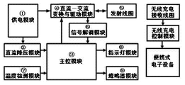
Fig. 1 is that portable electric appts wireless charging device functional module of the present invention connects block diagram.
The explanation block diagram that Fig. 2 is the wireless energy receiving course.
The linear voltage stabilization structural circuit figure that Fig. 3 is the DC decompression module.
The switching power circuit figure that Fig. 4 is the DC decompression module.
The circuit diagram that Fig. 5 is AC-DC converter and driver module.
Fig. 6 is signal demodulation module functional block diagram.
Fig. 7 is signal demodulating circuit figure.
Embodiment
Further explain the embodiment of portable electric appts wireless charging device of the present invention below in conjunction with accompanying drawing, but be noted that enforcement of the present invention is not limited to following execution mode.
Referring to Fig. 1.A kind of portable electric appts wireless charging device, comprise energy emitter and energy receiving system; Described energy emitter comprise supply module 1., the DC decompression module 2., main control module 3., DC-AC conversion and driver module 4., transmitting coil 5., the signal demodulation module 6. and temperature detecting module 7., indicating lamp module 8. with the buzzer module 9.: described supply module a part of city electric energy that 1. (external power source transformer or USB interface) provides is for 3. main control module provides power supply through 2. voltage reduction module is adjusted after, and described main control module is 3. for coordinating and the realization of control charge function; And the DC-AC that 3. most of electric energy that 1. supply module provides is controlled via main control module conversion and driver module adjustment 4. realize the conversion of DC-AC electric energy, more 5. energy are launched through transmitting coil.
Described energy receiving system comprises wireless charging control module and wireless charging receiving coil: the wireless charging receiving coil is with the mode received energy of electromagnetic induction, after conversion, it is the portable electric appts wireless charging, feedback information is loaded into to transmitting coil simultaneously, after 6. the signal demodulation module is processed, for main control module, 3. analyzes, adjust charge parameter.
The receiving course of wireless energy is (referring to Fig. 2): the energy receiving coil is after (11) (being " the wireless charging receiving coil " in Fig. 1) senses transmitting coil energy 5., through rectification module (12) rectifying and wave-filtering be metastable direct voltage, described voltage by voltage conversion circuit (13) voltage stabilizing to target voltage (as 5V), for (16) the load of portable electric appts powers; Simultaneously, rectification module is crossed the signal modulation module (12) to the MCU information exchange that (15) (being " the wireless charging control module " in Fig. 1) provides power supply, MCU (15) to gather reception and is (14) fed back to the energy transmitting terminal, thereby forms the receiving course of a set of wireless energy.
When making concrete wireless charging device, described energy emitter should be made to an independently wireless charging device, this device can comprise shell and the inner several parts of energy transmitting coil, ferrite, aluminium sheet, charging control circuit and external power source thereof.Described energy receiving system is arranged on corresponding portable electric appts.Described energy receiving system mainly comprises wireless charging control module and wireless charging energy receiving coil, and the electric energy received by the wireless charging control module can be stored in the rechargeable battery of portable electric appts.Described energy emitter and described energy receiving system are the structural members independently, minute be arranged for two.When charging, described portable electric appts is pressed close to described wireless charging device, by the device that energy is launched and energy receives, portable electric appts is carried out to wireless charging.During charging, 7. 3. main control module monitor described transmitting coil variations in temperature 5. by described temperature detecting module, adjusts in time charge parameter, prevents that the energy emitter is overheated.
The formation of described each module and concrete acting as:
1. described supply module adopts MICRO-USB interface, the MINI-USB of transformer-supplied or the standard of employing to connect power supply, is provided with the 5V adapter, and concrete parts can adopt the product that supply is arranged on the market.Its function is: for main control module 3. the 220V civil power can be converted to the 5V direct current; Also for the DC-AC conversion, with driver module, 4. power simultaneously.
2. described DC decompression module can adopt the form of linear voltage stabilization structure (LDO) circuit or Switching Power Supply (DC-BUCK) circuit.Described DC decompression module linear voltage stabilization structural circuit figure 2. is shown in Fig. 3, and wherein, U4 is the linear voltage stabilization chip, and C10, C11 are respectively input shunt capacitance and output decoupling capacitor, and purpose is filtering input and output clutters.Described DC decompression module switching power circuit figure 2. is shown in Fig. 4, and wherein, C11 is the input shunt capacitance, and purpose is filtering high frequency clutter, and a stable input voltage is provided.U4, D2, L2 form switching power circuit, and the output feedback that R10, R11 are Switching Power Supply detects, and are that R10 and R11 dividing potential drop and internal reference compare herein, carry out the switching frequency of by-pass cock power supply, and C16 is electric capacity of voltage regulation, and stable Voltage-output is provided.Described DC decompression module function 2. is: the DC high voltage that 1. supply module is inputted is converted to 3. available DC low-voltage of main control module.
3. described main control module consists of main control chip MCU, the internal composition program, for controlling, coordinate the work of whole wireless charging device, comprise that conversion, detection curent change, controlling magnetic field tranmitting frequency, the control indicator light of controlling DC-AC show and buzzer warning, receive the information of temperature detection.
Described DC-AC conversion is shown in Fig. 5 with driver module circuit 4., wherein, U6 is common metal-oxide-semiconductor driver, 3. PWM, EN signal are provided by main control module, the function of this part is signal driver metal-oxide-semiconductor 3. according to main control module, change direct current signal into alternating signal, AC signal is added to transmitting coil and 5. goes up, 5. energy is launched by transmitting coil.
5. described transmitting coil consists of coil ferrite assembly and series resonance electric capacity, its function is: receive AC-DC converter and driver module alternating signal 4., for the wireless charging receiving coil of energy receiving system provides the magnetic field of alternation, carry out the transmission of energy.
Described signal demodulation module signal demodulation part 6. comprises: signal every directly 1. module, signal filtering module, signal amplification module, signal every directly 2. module and signal shaping module (referring to Fig. 6).
Described signal demodulation module signal demodulating circuit 6. is (referring to Fig. 6 and 7):
Signal every directly 1. module and signal filtering module comprise that 3. 2. 1. label reach chip U1A, this part realize signal every straight and add benchmark job, the signal that is about to high benchmark is changed to the signal of low benchmark; Wherein: 1. locating C3 is capacitance, the direct current component in signal can be taken away; 2. locate to form low-pass first order filter by R2, C4, can be by the filtering of high frequency clutter; 3. locate R4, R6 and U1A chip and form the benchmark loaded circuit, this benchmark loaded circuit adds reference voltage can to the AC signal of front end after straight, and the size of reference voltage is regulated by R4, R6 dividing potential drop, and increasing capacitor C 5 is in order to increase the stability of reference voltage.
The signal amplification module comprises and 4. 5. reaches chip U1B part, the major function of this part is amplified the small-signal after straight, wherein multiplication factor is regulated by R1, R3, negative feedback adds that capacitor C 2 is in order to reduce the multiplication factor of the high frequency clutter in signal, thereby reach the effect of filtering, it is in order to increase the stability of power supply that power supply VCC place increases filter capacitor, thereby keeps chip energy works fine.
Signal every directly 2. module comprise and 6. 7. 8. reach the U1C part, the function of this part every 1. module directly, realizes that signal reloads reference signal and signal is carried out to filtering with signal.
9. the signal shaping module comprises 10. U1D, the AC signal that to amplify every directly from part is shaped as the discernible TTL signal of single-chip microcomputer, the R11 wherein 9. located, R13 provide reference voltage to signal shaping, and reference voltage can be realized by the dividing potential drop ratio of these two resistance; 10. the R7 located and the R9 of front end form and U1D forms hysteresis loop comparator, and parameter is arranged by the R9 of R7 and front end.
Described temperature detecting module function 7. is: detect the temperature conditions of wireless charging device inside and notify main control module 3., 3. main control module is adjusted and definite charge parameter accordingly, keeps the normal temperature of wireless charging device.
Described indicating lamp module function 8. is: to replace the real-time operating state of mode display radio charging device of gradual change, can adopt one or more LED light.
Described buzzer module function 9. is reminding user: wireless charging device has abnormal generation.
Due to temperature detecting module 7., indicating lamp module 8., 9. the buzzer module be the module commonly used of versatility, adopts market to have the Related product of supply to get final product, herein without special requirement.
The course of work of portable electric appts wireless charging device of the present invention is:
(1) through AC-DC converter and driver module, (AC rectification is direct current to the current signal that produces alternation in the energy emitter, direct current is converted to oscillating current, again oscillating current is amplified, sends into transmitting coil), make the energy emitter produce the magnetic field of alternation.
(2) by the close energy emitter of energy receiving system, make it to be arranged in the magnetic field of alternation, produce induced current in the wireless charging receiving coil.
(3) the wireless charging control module is sent into the portable electric appts internal circuit after induced current is processed, and is the battery charging of portable electric appts.
(4) portable electric appts, according to the charge condition of self, is determined institute's energy requirement and feedback information is transmitted to the energy emitter through the signal demodulation module, makes the main control module of energy emitter adjust the energy that it is sent.
Claims (3)
1. a portable electric appts wireless charging device, comprise energy emitter and energy receiving system, it is characterized in that: described energy emitter comprises supply module, DC decompression module, main control module, DC-AC conversion and driver module, energy transmitting coil, signal demodulation module and temperature detecting module: a part of electric energy that described supply module provides is for main control module provides power supply after the voltage reduction module adjustment, and described main control module is for coordinating and control the realization of charge function; And most of electric energy that supply module provides is realized the conversion of AC-DC electric energy, then through the energy transmitting coil, energy is launched via the DC-AC conversion of master control module controls and the adjustment of driver module; Described energy receiving system comprises wireless charging control module and wireless charging energy receiving coil: wireless charging energy receiving coil is in the mode of electromagnetic induction, the perhaps mode received energy of magnetic resonance, after conversion, it is the portable electric appts wireless charging, feedback information is loaded into to the energy receiving coil simultaneously, received by the energy transmitting coil through induction, supply the main control module analysis after the signal demodulation module is processed, adjust charge parameter; Described energy emitter is made to an independently wireless charging device, described energy receiving system is arranged on corresponding portable electric appts, described portable electric appts is pressed close to described wireless charging device, by the device that energy is launched and energy receives, portable electric appts is carried out to wireless charging; During charging, main control module is monitored the variations in temperature of described transmitting coil by described temperature detecting module, adjust in time charge parameter, prevents that the energy emitter is overheated.
2. portable electric appts wireless charging device according to claim 1, is characterized in that, is provided with indicating lamp module and buzzer module on described energy emitter; In charging process, indicating lamp module and buzzer module can show charged state and the abnormal prompting of being charged.
3. portable electric appts wireless charging device according to claim 1, is characterized in that, described supply module is provided with USB plug, can with city, be electrically connected to by computer.
Priority Applications (1)
| Application Number | Priority Date | Filing Date | Title |
|---|---|---|---|
| CN201310399324.2A CN103490486A (en) | 2013-09-05 | 2013-09-05 | Wireless charging device of portable electronic equipment |
Applications Claiming Priority (1)
| Application Number | Priority Date | Filing Date | Title |
|---|---|---|---|
| CN201310399324.2A CN103490486A (en) | 2013-09-05 | 2013-09-05 | Wireless charging device of portable electronic equipment |
Publications (1)
| Publication Number | Publication Date |
|---|---|
| CN103490486A true CN103490486A (en) | 2014-01-01 |
Family
ID=49830513
Family Applications (1)
| Application Number | Title | Priority Date | Filing Date |
|---|---|---|---|
| CN201310399324.2A Pending CN103490486A (en) | 2013-09-05 | 2013-09-05 | Wireless charging device of portable electronic equipment |
Country Status (1)
| Country | Link |
|---|---|
| CN (1) | CN103490486A (en) |
Cited By (12)
| Publication number | Priority date | Publication date | Assignee | Title |
|---|---|---|---|---|
| CN103944417A (en) * | 2014-05-16 | 2014-07-23 | 山东共达电声股份有限公司 | Insert row |
| CN103944418A (en) * | 2014-05-16 | 2014-07-23 | 山东共达电声股份有限公司 | Power adapter |
| CN104258564A (en) * | 2014-09-25 | 2015-01-07 | 苏州乐聚一堂电子科技有限公司 | Radio frequency inductive pattern board |
| CN104459263A (en) * | 2014-12-05 | 2015-03-25 | 深圳市创荣发电子有限公司 | Pointer ampere meter capable of automatically shifting gears |
| CN104505957A (en) * | 2014-12-25 | 2015-04-08 | 新东圳(苏州)智能科技有限公司 | Wireless power supply communication device |
| CN105379137A (en) * | 2014-01-08 | 2016-03-02 | 联发科技(新加坡)私人有限公司 | Wireless power receiver with programmable power path |
| CN105490358A (en) * | 2015-07-03 | 2016-04-13 | 广东云控照明科技有限公司 | Portable intelligent touch panel wireless charging emission device |
| CN105846526A (en) * | 2016-06-14 | 2016-08-10 | 安徽机电职业技术学院 | Wireless charging system for mobile electronic equipment |
| CN106451820A (en) * | 2016-11-23 | 2017-02-22 | 成都信息工程大学 | Wireless power supply and distribution socket system |
| CN106469935A (en) * | 2015-08-11 | 2017-03-01 | 纽艾吉科技有限公司 | Wireless charging system and its wireless power transmission device and wireless power transmission method |
| CN107180486A (en) * | 2017-04-24 | 2017-09-19 | 上海锐灵电子科技有限公司 | A kind of wireless charging device, wireless charging charging method and system using it |
| CN109088453A (en) * | 2018-08-17 | 2018-12-25 | 华东师范大学 | A kind of wireless charging device for portable Medical Devices |
Citations (5)
| Publication number | Priority date | Publication date | Assignee | Title |
|---|---|---|---|---|
| CN201504123U (en) * | 2009-09-18 | 2010-06-09 | 陕西伏特龙电力有限公司 | Vehicle-mounted non-contact power supply |
| US20110025133A1 (en) * | 2008-04-03 | 2011-02-03 | Koninklijke Philips Electronics N.V. | Wireless power transmission system |
| CN102611215A (en) * | 2012-04-10 | 2012-07-25 | 海尔集团公司 | Wireless electric energy transmitting device and wireless charging system |
| CN202712982U (en) * | 2012-06-04 | 2013-01-30 | 比亚迪股份有限公司 | Sending device of wireless charging and wireless charging system |
| CN103051040A (en) * | 2013-01-28 | 2013-04-17 | 罗利文 | Capacitive energy storage type rechargeable battery and charging device thereof |
-
2013
- 2013-09-05 CN CN201310399324.2A patent/CN103490486A/en active Pending
Patent Citations (5)
| Publication number | Priority date | Publication date | Assignee | Title |
|---|---|---|---|---|
| US20110025133A1 (en) * | 2008-04-03 | 2011-02-03 | Koninklijke Philips Electronics N.V. | Wireless power transmission system |
| CN201504123U (en) * | 2009-09-18 | 2010-06-09 | 陕西伏特龙电力有限公司 | Vehicle-mounted non-contact power supply |
| CN102611215A (en) * | 2012-04-10 | 2012-07-25 | 海尔集团公司 | Wireless electric energy transmitting device and wireless charging system |
| CN202712982U (en) * | 2012-06-04 | 2013-01-30 | 比亚迪股份有限公司 | Sending device of wireless charging and wireless charging system |
| CN103051040A (en) * | 2013-01-28 | 2013-04-17 | 罗利文 | Capacitive energy storage type rechargeable battery and charging device thereof |
Cited By (14)
| Publication number | Priority date | Publication date | Assignee | Title |
|---|---|---|---|---|
| CN105379137B (en) * | 2014-01-08 | 2018-01-02 | 联发科技(新加坡)私人有限公司 | Radio source receiver with programmable power supply path |
| CN105379137A (en) * | 2014-01-08 | 2016-03-02 | 联发科技(新加坡)私人有限公司 | Wireless power receiver with programmable power path |
| CN103944418A (en) * | 2014-05-16 | 2014-07-23 | 山东共达电声股份有限公司 | Power adapter |
| CN103944417A (en) * | 2014-05-16 | 2014-07-23 | 山东共达电声股份有限公司 | Insert row |
| CN104258564A (en) * | 2014-09-25 | 2015-01-07 | 苏州乐聚一堂电子科技有限公司 | Radio frequency inductive pattern board |
| CN104459263A (en) * | 2014-12-05 | 2015-03-25 | 深圳市创荣发电子有限公司 | Pointer ampere meter capable of automatically shifting gears |
| CN104505957A (en) * | 2014-12-25 | 2015-04-08 | 新东圳(苏州)智能科技有限公司 | Wireless power supply communication device |
| CN105490358A (en) * | 2015-07-03 | 2016-04-13 | 广东云控照明科技有限公司 | Portable intelligent touch panel wireless charging emission device |
| CN106469935A (en) * | 2015-08-11 | 2017-03-01 | 纽艾吉科技有限公司 | Wireless charging system and its wireless power transmission device and wireless power transmission method |
| CN106469935B (en) * | 2015-08-11 | 2019-07-19 | 纽艾吉科技有限公司 | Wireless charging system and its wireless power transmission device and wireless power transmission method |
| CN105846526A (en) * | 2016-06-14 | 2016-08-10 | 安徽机电职业技术学院 | Wireless charging system for mobile electronic equipment |
| CN106451820A (en) * | 2016-11-23 | 2017-02-22 | 成都信息工程大学 | Wireless power supply and distribution socket system |
| CN107180486A (en) * | 2017-04-24 | 2017-09-19 | 上海锐灵电子科技有限公司 | A kind of wireless charging device, wireless charging charging method and system using it |
| CN109088453A (en) * | 2018-08-17 | 2018-12-25 | 华东师范大学 | A kind of wireless charging device for portable Medical Devices |
Similar Documents
| Publication | Publication Date | Title |
|---|---|---|
| CN103490486A (en) | Wireless charging device of portable electronic equipment | |
| EP2804287B1 (en) | Charger and charging system | |
| JP2017506873A (en) | Monitoring or controlling charging current in a resonantly regulated inductive charger | |
| CN106329689B (en) | Adapter and method for realizing charging thereof | |
| CN109787337B (en) | Composite power supply type wireless temperature measuring sensor and control method thereof | |
| EP2955528A1 (en) | Near-infrared reading device and ammeter | |
| CN201956730U (en) | Portable alternating current power supply externally connected with storage battery | |
| CN202651859U (en) | Charging circuit for reducing energy consumption of charger in standby state and charger | |
| CN206211626U (en) | Coupled resonance wireless charging portable power source based on frequency-tracking | |
| CN202651766U (en) | Single-phase motor protective device | |
| CN202111492U (en) | Multifunctional charger | |
| CN203522250U (en) | Three-in-one wireless charging device | |
| CN207603469U (en) | A kind of strong switching power supply of job stability | |
| CN108288872A (en) | A kind of lithium battery quick charge device of current automatic adaptation | |
| CN104079047A (en) | Wireless charger | |
| CN205283221U (en) | Fill by force and fill portable power source soon | |
| CN206775232U (en) | A kind of wireless charging device suitable for intelligent access control system | |
| CN107482739A (en) | A kind of battery induction charging device and its system and control method | |
| CN112067891B (en) | Electric quantity metering circuit and ammeter | |
| CN204968151U (en) | Intelligence lamps and lanterns with wireless function of charging stage by stage | |
| CN210536489U (en) | Improved adapter circuit | |
| CN107634568A (en) | A kind of power supply adaptor | |
| CN204009391U (en) | A kind of clock and watch with wireless charger | |
| CN203859778U (en) | Wireless charging power supply mobile phone back cover | |
| CN205141297U (en) | Provide wireless intelligent multiple socket -outlet who charges that pays in default distance |
Legal Events
| Date | Code | Title | Description |
|---|---|---|---|
| C06 | Publication | ||
| PB01 | Publication | ||
| C10 | Entry into substantive examination | ||
| SE01 | Entry into force of request for substantive examination | ||
| C12 | Rejection of a patent application after its publication | ||
| RJ01 | Rejection of invention patent application after publication |
Application publication date: 20140101 |