CN103472558A - Multifunctional optical lens device clamping tool - Google Patents
Multifunctional optical lens device clamping tool Download PDFInfo
- Publication number
- CN103472558A CN103472558A CN2013104140957A CN201310414095A CN103472558A CN 103472558 A CN103472558 A CN 103472558A CN 2013104140957 A CN2013104140957 A CN 2013104140957A CN 201310414095 A CN201310414095 A CN 201310414095A CN 103472558 A CN103472558 A CN 103472558A
- Authority
- CN
- China
- Prior art keywords
- optical lens
- head
- matrix
- multifunctional optical
- lens device
- Prior art date
- Legal status (The legal status is an assumption and is not a legal conclusion. Google has not performed a legal analysis and makes no representation as to the accuracy of the status listed.)
- Granted
Links
Images



Landscapes
- Lens Barrels (AREA)
Abstract
本发明公开了一种多功能光学透镜器件夹持工具,它包括基体、拉簧、可换夹具头和压臂,压臂的中部通过转轴铰接在基体上,压臂的一端具有压头,可换夹具头可拆卸式地插装在基体上,并且可换夹具头上设置有定位部,该定位部与压头配合以便夹持光学透镜,拉簧的一端连接在基体上,拉簧的另一端连接在压臂上。本发明能够夹持多种形状和不同大小的透镜,提高其通用性,并且压紧均匀,节约成本。
This invention discloses a multifunctional optical lens clamping tool, comprising a base, a tension spring, a replaceable clamping head, and a pressure arm. The middle part of the pressure arm is hinged to the base via a pivot, and one end of the pressure arm has a pressure head. The replaceable clamping head is detachably inserted into the base and is provided with a positioning part that cooperates with the pressure head to clamp the optical lens. One end of the tension spring is connected to the base, and the other end of the tension spring is connected to the pressure arm. This invention can clamp lenses of various shapes and sizes, improving its versatility, providing uniform clamping, and saving costs.
Description
技术领域 technical field
本发明涉及一种多功能光学透镜器件夹持工具。 The invention relates to a multifunctional optical lens device clamping tool.
背景技术 Background technique
目前,在激光器的生产制造中,常用到很多形状和大小各不相同的微小透镜,常用的主要有圆型柱状透镜与方形透镜。在使用这些微小透镜时常要用到很多的微小型夹具,根据在研发和生产阶段的不同用途,经常需要加工各种不同大小形状的专用夹持工具,来实现微小透镜的夹持与定位。如果有一种通用的多功能的标准夹具,这将大大减少夹具加工的数量,从而节约加工成本,提高生产效率。 At present, in the production and manufacture of lasers, many tiny lenses with different shapes and sizes are commonly used, and the commonly used ones are mainly cylindrical lenses and square lenses. When using these tiny lenses, a lot of tiny fixtures are often used. According to different uses in the R&D and production stages, it is often necessary to process special clamping tools of various sizes and shapes to realize the clamping and positioning of tiny lenses. If there is a universal multifunctional standard fixture, it will greatly reduce the number of fixture processing, thereby saving processing costs and improving production efficiency.
发明内容 Contents of the invention
本发明所要解决的技术问题是克服现有技术的缺陷,提供一种多功能光学透镜器件夹持工具,它能够夹持多种形状和不同大小的透镜,提高其通用性,并且压紧均匀,节约成本。 The technical problem to be solved by the present invention is to overcome the defects of the prior art, and provide a multifunctional optical lens device clamping tool, which can clamp lenses of various shapes and sizes, improve its versatility, and compress evenly, save costs.
本发明解决上述技术问题采取的技术方案是:一种多功能光学透镜器件夹持工具,它包括基体、拉簧、可换夹具头和压臂,压臂的中部通过转轴铰接在基体上,压臂的一端具有压头,可换夹具头可拆卸式地插装在基体上,并且可换夹具头上设置有定位部,该定位部与压头配合以便夹持光学透镜,拉簧的一端连接在基体上,拉簧的另一端连接在压臂上。 The technical scheme adopted by the present invention to solve the above-mentioned technical problems is: a multifunctional optical lens device clamping tool, which includes a base body, a tension spring, an interchangeable clamp head and a pressing arm, the middle part of the pressing arm is hinged on the base body through a rotating shaft, One end of the arm has a pressure head, and the interchangeable fixture head is detachably inserted on the base body, and the replaceable fixture head is provided with a positioning part, which cooperates with the pressure head to clamp the optical lens, and one end of the tension spring is connected On the base, the other end of the extension spring is connected to the pressing arm.
进一步,所述的压臂的压头为圆弧面结构,并且压头上具有压触线。 Further, the pressing head of the pressing arm has a circular arc surface structure, and the pressing head has a pressing contact line.
进一步,所述的可换夹具头的定位部为V型槽结构。 Further, the positioning part of the replaceable clamp head is a V-shaped groove structure.
进一步,所述的V型槽结构的定位部的槽向与转轴的轴向平行或垂直。 Further, the groove direction of the positioning portion of the V-shaped groove structure is parallel to or perpendicular to the axial direction of the rotating shaft.
进一步,所述的可换夹具头的定位部为平面结构。 Further, the positioning part of the replaceable clamp head is a planar structure.
进一步,所述的基体上安装有下拉簧挂销,所述的压臂上安装有上拉簧挂销,所述的拉簧的一端连接在上拉簧挂销上,所述的拉簧的另一端连接在下拉簧挂销上。 Further, the lower spring hanging pin is installed on the base, the upper tension spring hanging pin is installed on the pressing arm, one end of the extension spring is connected to the upper extension spring hanging pin, and the extension spring The other end is attached to the lower hanger pin.
进一步,所述的基体上开有插装可换夹具头的插装孔,基体上还开有与插装孔连通的锁紧劈空槽,基体上还通过螺纹连接有锁紧螺钉,该锁紧螺钉穿过锁紧劈空槽,当拧紧锁紧螺钉时,锁紧劈空槽收窄,同时插装孔径向收缩以便锁紧可换夹具头,当拧松锁紧螺钉时,锁紧劈空槽放宽,同时插装孔径向放大以便松开可换夹具头。 Further, the base body is provided with an insertion hole for inserting the replaceable fixture head, and the base body is also provided with a locking split groove communicating with the insertion hole, and the base body is also threaded with a locking screw. The tightening screw passes through the locking splitting slot. When the locking screw is tightened, the locking splitting slot narrows, and at the same time the insertion hole shrinks radially to lock the replaceable fixture head. When the locking screw is loosened, the locking splitting The empty slot is widened, and the inserting hole is radially enlarged to loosen the replaceable clamp head.
更进一步,所述的压臂上通过螺纹连接有两个底端可抵接在基体上的限位螺钉,并且两个限位螺钉分别位于转轴的两侧。 Furthermore, the pressing arm is threadedly connected with two limit screws whose bottom ends can be abutted against the base body, and the two limit screws are respectively located on both sides of the rotating shaft.
采用了上述技术方案后,本发明具有以下的有益效果: After adopting above-mentioned technical scheme, the present invention has following beneficial effect:
1、本发明采用拉簧的拉力作为预紧力,通过转轴为中心铰接支点,在拉簧的拉力下达到对光学透镜的压紧作用,能保证每一次的压力一致。压紧力均匀; 1. The present invention adopts the tension of the extension spring as the pre-tightening force, and through the rotating shaft as the center hinge fulcrum, the compression effect on the optical lens is achieved under the tension of the extension spring, which can ensure that the pressure is consistent every time. Uniform pressing force;
2、本发明采用可换夹具头结构,便于夹持各种形状、不同大小尺寸的光学透镜,在研发或生产过程中能够做到灵活使用; 2. The present invention adopts a replaceable fixture head structure, which is convenient for clamping optical lenses of various shapes and sizes, and can be used flexibly in the process of research and development or production;
3、本发明采用圆弧面结构的压头,并且具有压触线,保证任何一点的压头的压紧作用都是线接触,从而避免了过定位,减少对光学透镜的夹持应力;本发明提供了可换夹具头的压头的三种结构,可以实现三点或一点一面的定位方式。 3. The present invention adopts an indenter with a circular arc surface structure and has a pressure contact line to ensure that the pressing effect of any point of the indenter is a line contact, thereby avoiding over-positioning and reducing the clamping stress on the optical lens; The invention provides three structures of the pressure head of the interchangeable fixture head, which can realize the positioning mode of three points or one point and one side.
4、本发明还设置了两个限位螺钉,通过设置在压臂按压部的限位螺钉可以限定压臂相对于基体的最上限的旋转位置,通过另一个限位螺钉可以限定压臂相对于基体的最下限的旋转位置。 4. The present invention is also provided with two limit screws. The uppermost rotation position of the press arm relative to the base can be limited by the limit screw arranged on the pressing part of the press arm. The lowermost rotational position of the base.
附图说明 Description of drawings
图1为本发明的多功能光学透镜器件夹持工具的结构示意图; Fig. 1 is the structural representation of multifunctional optical lens device clamping tool of the present invention;
图2为图1的左视图; Fig. 2 is the left view of Fig. 1;
图3为本发明的多功能光学透镜器件夹持工具的立体图; Fig. 3 is the perspective view of multifunctional optical lens device holding tool of the present invention;
图4为本发明的多功能光学透镜器件夹持工具的装配爆炸图; Fig. 4 is the assembly explosion diagram of multifunctional optical lens device holding tool of the present invention;
图5为本发明的多功能光学透镜器件夹持工具的工作原理图; Fig. 5 is a working principle diagram of the multifunctional optical lens device holding tool of the present invention;
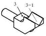
图6为本发明的可换夹具头的第一种结构的结构示意图; Fig. 6 is a structural schematic diagram of the first structure of the replaceable clamp head of the present invention;
图7为本发明的可换夹具头的第二种结构的结构示意图; Fig. 7 is a structural schematic diagram of the second structure of the replaceable clamp head of the present invention;
图8为本发明的可换夹具头的第三种结构的结构示意图。 Fig. 8 is a structural schematic diagram of the third structure of the replaceable clamp head of the present invention.
具体实施方式 Detailed ways
为了使本发明的内容更容易被清楚地理解,下面根据具体实施例并结合附图,对本发明作进一步详细的说明。 In order to make the content of the present invention more clearly understood, the present invention will be further described in detail below based on specific embodiments and in conjunction with the accompanying drawings.
如图1~8所示,一种多功能光学透镜器件夹持工具,它包括基体1、拉簧2、可换夹具头3和压臂4,压臂4的中部通过转轴6铰接在基体1上,压臂4的一端具有压头4-1,可换夹具头3可拆卸式地插装在基体1上,并且可换夹具头3上设置有定位部3-1,该定位部3-1与压头4-1配合以便夹持光学透镜,拉簧2的一端连接在基体1上,拉簧2的另一端连接在压臂4上。本发明采用拉簧2的拉力作为预紧力,通过转轴6为中心铰接支点,在拉簧2的拉力下达到对光学透镜的压紧作用,能保证每一次的压力一致。压紧力均匀;本发明采用可换夹具头3结构,便于夹持各种形状、不同大小尺寸的光学透镜,在研发或生产过程中能够做到灵活使用;
As shown in Figures 1 to 8, a multifunctional optical lens device clamping tool includes a base body 1, a
如图1所示,压臂4的压头4-1为圆弧面结构,并且压头4-1上具有压触线。这样就能保证任何一点的压头4-1的压紧作用都是线接触,从而避免了过定位,减少对光学透镜的夹持应力。
As shown in Figure 1, the pressure head 4-1 of the
如图4所示,基体1上安装有下拉簧挂销7,压臂4上安装有上拉簧挂销8,拉簧2的一端连接在上拉簧挂销8上,拉簧的另一端连接在下拉簧挂销7上。
As shown in Figure 4, the lower spring hanging pin 7 is installed on the base body 1, the upper tension spring hanging pin 8 is installed on the
如图4所示,基体1上开有插装可换夹具头3的插装孔1-1,基体1上还开有与插装孔连通的锁紧劈空槽1-3,基体1上还通过螺纹连接有锁紧螺钉5,该锁紧螺钉5穿过锁紧劈空槽1-3,当拧紧锁紧螺钉5时,锁紧劈空槽1-3收窄,同时插装孔1-1径向收缩以便锁紧可换夹具头3,当拧松锁紧螺钉5时,锁紧劈空槽1-3放宽,同时插装孔1-1径向放大以便松开可换夹具头3。
As shown in Figure 4, the substrate 1 is provided with an insertion hole 1-1 for inserting the
如图4所示,压臂4上通过螺纹连接有两个底端可抵接在基体1上的限位螺钉9,并且两个限位螺钉9分别位于转轴6的两侧。通过设置在压臂4按压部的限位螺钉9可以限定压臂4相对于基体1的最上限的旋转位置,通过另一个限位螺钉9可以限定压臂4相对于基体1的最下限的旋转位置。
As shown in FIG. 4 , the
如图6所示,可换夹具头3的定位部3-1可以为V型槽结构,并且V型槽结构的定位部3-1的槽向与转轴6的轴向平行。如图7所示,可换夹具头3的定位部3-1可以为V型槽结构,并且V型槽结构的定位部3-1的槽向与转轴6的轴向垂直。如图8所示,可换夹具头3的定位部3-1可以为平面结构;以上三种结构,可以实现本发明三点或一点一面的定位方式,但定位部3-1的结构不限于以上三种。
As shown in FIG. 6 , the positioning portion 3 - 1 of the
本发明的工作流程如下: Work process of the present invention is as follows:
1、基体1后面开有螺纹孔1-2,利用基体1后部螺纹孔1-2与其它调整架连接好; 1. There are threaded holes 1-2 at the back of the base body 1, and the threaded holes 1-2 at the back of the base body 1 are used to connect with other adjustment frames;
2、压臂4的后端设置有手柄4-2,用手按下手柄A处,抬起压臂4;
2. The rear end of the
3、将需要的光学透镜放入定位部3-1(V型槽或平面)上,然后轻轻的放下压臂4,在拉簧2的拉力作用下压臂4将所用的光学透镜压紧;
3. Put the required optical lens into the positioning part 3-1 (V-shaped groove or plane), then gently put down the
4、通过调整调整架以实现光学透镜器件在光路中的调整。 4. Adjust the optical lens device in the optical path by adjusting the adjustment frame.
以上所述的具体实施例,对本发明解决的技术问题、技术方案和有益效果进行了进一步详细说明,所应理解的是,以上所述仅为本发明的具体实施例而已,并不用于限制本发明,凡在本发明的精神和原则之内,所做的任何修改、等同替换、改进等,均应包含在本发明的保护范围之内。 The specific embodiments described above have further described the technical problems, technical solutions and beneficial effects solved by the present invention in detail. It should be understood that the above descriptions are only specific embodiments of the present invention and are not intended to limit the present invention. Any modification, equivalent replacement, improvement, etc. made within the spirit and principle of the present invention shall be included in the protection scope of the present invention.
Claims (8)
Priority Applications (1)
| Application Number | Priority Date | Filing Date | Title |
|---|---|---|---|
| CN201310414095.7A CN103472558B (en) | 2013-09-12 | 2013-09-12 | Optical lens device clamping device |
Applications Claiming Priority (1)
| Application Number | Priority Date | Filing Date | Title |
|---|---|---|---|
| CN201310414095.7A CN103472558B (en) | 2013-09-12 | 2013-09-12 | Optical lens device clamping device |
Publications (2)
| Publication Number | Publication Date |
|---|---|
| CN103472558A true CN103472558A (en) | 2013-12-25 |
| CN103472558B CN103472558B (en) | 2016-04-20 |
Family
ID=49797472
Family Applications (1)
| Application Number | Title | Priority Date | Filing Date |
|---|---|---|---|
| CN201310414095.7A Active CN103472558B (en) | 2013-09-12 | 2013-09-12 | Optical lens device clamping device |
Country Status (1)
| Country | Link |
|---|---|
| CN (1) | CN103472558B (en) |
Cited By (5)
| Publication number | Priority date | Publication date | Assignee | Title |
|---|---|---|---|---|
| CN105289929A (en) * | 2015-10-26 | 2016-02-03 | 佳马机械涂覆科技(苏州)有限公司 | Fixing clamp for dispenser glue barrel |
| CN109336404A (en) * | 2018-12-05 | 2019-02-15 | 西安天穹智能机器科技有限公司 | A slender cylindrical glass rod clamping device |
| CN109739003A (en) * | 2019-02-26 | 2019-05-10 | 武汉光迅科技股份有限公司 | A kind of interference protection flexible fastening pawl |
| CN111266735A (en) * | 2020-02-21 | 2020-06-12 | 中南大学 | Four-piece type optical device coupling welding equipment based on power detection |
| CN111338163A (en) * | 2018-12-19 | 2020-06-26 | 中强光电股份有限公司 | Optical component fixing structure and projector |
Citations (6)
| Publication number | Priority date | Publication date | Assignee | Title |
|---|---|---|---|---|
| US6061191A (en) * | 1998-09-05 | 2000-05-09 | Mustek Systems Inc. | Lens fixer device for scanner |
| CN2490593Y (en) * | 2001-08-08 | 2002-05-08 | 力捷电脑股份有限公司 | Holding structure for optical lens |
| CN101118312A (en) * | 2006-08-04 | 2008-02-06 | 振宇光学有限公司 | Clamping structure of magnifier |
| CN202219464U (en) * | 2011-09-23 | 2012-05-16 | 博世汽车部件(苏州)有限公司 | Fixture component |
| CN203164498U (en) * | 2013-03-27 | 2013-08-28 | 四川省洪雅维国光学有限公司 | Experiment used optical lens clamping device |
| CN203465462U (en) * | 2013-09-12 | 2014-03-05 | 江苏天元激光科技有限公司 | Multifunctional optical lens device clamping tool |
-
2013
- 2013-09-12 CN CN201310414095.7A patent/CN103472558B/en active Active
Patent Citations (6)
| Publication number | Priority date | Publication date | Assignee | Title |
|---|---|---|---|---|
| US6061191A (en) * | 1998-09-05 | 2000-05-09 | Mustek Systems Inc. | Lens fixer device for scanner |
| CN2490593Y (en) * | 2001-08-08 | 2002-05-08 | 力捷电脑股份有限公司 | Holding structure for optical lens |
| CN101118312A (en) * | 2006-08-04 | 2008-02-06 | 振宇光学有限公司 | Clamping structure of magnifier |
| CN202219464U (en) * | 2011-09-23 | 2012-05-16 | 博世汽车部件(苏州)有限公司 | Fixture component |
| CN203164498U (en) * | 2013-03-27 | 2013-08-28 | 四川省洪雅维国光学有限公司 | Experiment used optical lens clamping device |
| CN203465462U (en) * | 2013-09-12 | 2014-03-05 | 江苏天元激光科技有限公司 | Multifunctional optical lens device clamping tool |
Cited By (7)
| Publication number | Priority date | Publication date | Assignee | Title |
|---|---|---|---|---|
| CN105289929A (en) * | 2015-10-26 | 2016-02-03 | 佳马机械涂覆科技(苏州)有限公司 | Fixing clamp for dispenser glue barrel |
| CN109336404A (en) * | 2018-12-05 | 2019-02-15 | 西安天穹智能机器科技有限公司 | A slender cylindrical glass rod clamping device |
| CN109336404B (en) * | 2018-12-05 | 2023-07-25 | 西安天穹智能机器科技有限公司 | Slender cylindrical glass rod clamping device |
| CN111338163A (en) * | 2018-12-19 | 2020-06-26 | 中强光电股份有限公司 | Optical component fixing structure and projector |
| US11686914B2 (en) | 2018-12-19 | 2023-06-27 | Coretronic Corporation | Optical component fixing structure and projector |
| CN109739003A (en) * | 2019-02-26 | 2019-05-10 | 武汉光迅科技股份有限公司 | A kind of interference protection flexible fastening pawl |
| CN111266735A (en) * | 2020-02-21 | 2020-06-12 | 中南大学 | Four-piece type optical device coupling welding equipment based on power detection |
Also Published As
| Publication number | Publication date |
|---|---|
| CN103472558B (en) | 2016-04-20 |
Similar Documents
| Publication | Publication Date | Title |
|---|---|---|
| CN202701859U (en) | Eccentric wheel type quick clamping vice | |
| CN103472558B (en) | Optical lens device clamping device | |
| CN103286598A (en) | Drilling fixture | |
| CN205599986U (en) | A anchor clamps that is used for piston rod inclined hole rotation to process | |
| CN111546252A (en) | Adaptive clamping vice | |
| CN207272791U (en) | A middle plate clamping jig with suction function | |
| CN103286597A (en) | Fixture | |
| CN204976130U (en) | Turning attachment of turning engine connecting rod | |
| CN203465462U (en) | Multifunctional optical lens device clamping tool | |
| CN208514130U (en) | A kind of clamping jaw | |
| CN104668985A (en) | Special clamp for machining square bottom surface of robot base | |
| CN204771648U (en) | Industrial robot transmission shaft keyway add clamping apparatus | |
| CN204019207U (en) | The special fixture of a kind of machining robot base upper surface | |
| CN204075806U (en) | The side pressure clamping device of product | |
| CN203380647U (en) | Jig for drilling inclined oil bolt holes | |
| CN203266457U (en) | Hydraulic flat tongs | |
| CN206779957U (en) | The clamp for machining of engine body | |
| CN107030509A (en) | A kind of turning attachment of turning engine link | |
| CN105538002A (en) | Special clamp assembly for drilling and grinding slice-type cylindrical part | |
| CN210741997U (en) | Novel wedge-shaped fatigue test fixture | |
| CN104128819A (en) | Clamp for slow wire feeding machine tool | |
| CN210615211U (en) | Boring cutter seat accessory processing equipment | |
| CN203566136U (en) | Adjustable clamping device used for welding stud | |
| CN102581656B (en) | Pushing mechanism and fixture therewith | |
| CN206105442U (en) | Mill flat anchor clamps |
Legal Events
| Date | Code | Title | Description |
|---|---|---|---|
| C06 | Publication | ||
| PB01 | Publication | ||
| C10 | Entry into substantive examination | ||
| SE01 | Entry into force of request for substantive examination | ||
| C14 | Grant of patent or utility model | ||
| GR01 | Patent grant | ||
| CP03 | Change of name, title or address |
Address after: Entrepreneurship Service Center, High-tech Zone, No. 99, Zhulin Road, Danyang City, Zhenjiang City, Jiangsu Province 212300 Patentee after: Jiangsu Skyera Laser Technology Co.,Ltd. Address before: 212300 No.8, high tech industrial concentration zone, Danyang City, Zhenjiang City, Jiangsu Province Patentee before: JIANGSU SKYERALASER TECHNOLOGY CO.,LTD. |
|
| CP03 | Change of name, title or address |