CN103438118A - Hydraulic clutch - Google Patents
Hydraulic clutch Download PDFInfo
- Publication number
- CN103438118A CN103438118A CN201310380391XA CN201310380391A CN103438118A CN 103438118 A CN103438118 A CN 103438118A CN 201310380391X A CN201310380391X A CN 201310380391XA CN 201310380391 A CN201310380391 A CN 201310380391A CN 103438118 A CN103438118 A CN 103438118A
- Authority
- CN
- China
- Prior art keywords
- input shaft
- output shaft
- piston
- friction plate
- face
- Prior art date
- Legal status (The legal status is an assumption and is not a legal conclusion. Google has not performed a legal analysis and makes no representation as to the accuracy of the status listed.)
- Pending
Links
Images
Landscapes
- Braking Arrangements (AREA)
Abstract
A hydraulic clutch comprises an input shaft, a braking shell, a piston, a spacer ring, a friction plate set, a flange plate, an output shaft and surface bearings. The input shaft is sleeved with the output shaft, and the braking shell is sleeved with the piston; the friction plate set is arranged between the input shaft and the output shaft, and the input shaft is sleeved with the friction plate set; the braking shell is arranged on the input shaft, the piston rod and the output shaft and connected with the flange plate through bolts; the surface bearings are placed between the end face of the output shaft and the end face of the flange plate and placed between the friction plate set and the piston; the spacer ring is located in the braking shell or located on the end face of one side of the braking shell through bolts. The hydraulic clutch has the advantages of being simple in structure, low in maintenance cost, large in transmitting torque, and high in transmitting efficiency.
Description
Technical field
The present invention relates to a kind of hydraulic coupling.
Background technique
The working principle of hydraulic coupling be exactly nothing but input shaft by the friction plate group from the incompatible output shaft output torque that allows, but, due to the defect that design exists, there is the not high shortcoming of efficiency that complicated structure, maintenance cost are very high, transmit in existing hydraulic coupling.
Summary of the invention
The object of the invention is to overcome the deficiency that prior art exists, and a kind of simple in structure, transmission efficiency is high, maintenance cost is low hydraulic coupling is provided.
The objective of the invention is to complete by following technical solution, it comprises input shaft, braking housing, piston, spacer ring, friction plate group, flanged plate, output shaft, plane bearing, described output sleeve is on input shaft, and described piston is placed on the drag housing body; Be placed with the friction plate group between this input shaft and output shaft, and the friction plate group is placed in input shaft; Described braking housing is assemblied on input shaft, piston and output shaft, and is connected with flanged plate by bolt.
As preferably, be placed with plane bearing between the end face of described output shaft and the end face of flanged plate, friction plate group and piston space are placed with plane bearing.
As preferably, described spacer ring is positioned at the braking housing or is positioned on a side end face of braking housing by bolt.
Beneficial effect of the present invention is: have simple in structurely, maintenance cost is low, and transmitting torque is large, the characteristics that transmission efficiency is high.
The accompanying drawing explanation
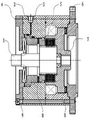
Fig. 1 is structural representation of the present invention.
Fig. 2 is another kind of structural representation of the present invention.
Label in accompanying drawing is respectively: 1, input shaft; 2, braking housing; 3, piston; 4, spacer ring; 5, friction plate group; 6, flanged plate; 7, output shaft; 8, plane bearing; 9, bolt.
Embodiment
Below in conjunction with accompanying drawing, the present invention is done to detailed introduction: as shown in accompanying drawing 1,2, the present invention includes input shaft 1, braking housing 2, piston 3, spacer ring 4, friction plate group 5, flanged plate 6, output shaft 7, plane bearing 8, described output shaft 7 is placed in (or input shaft 1 is placed on output shaft 7) on input shaft 1, and described piston 3 is placed on braking housing 2; 7 of this input shaft 1 and output shafts are placed with friction plate group 5, and friction plate group 5 is placed in input shaft 1; Described braking housing 2 is assemblied on input shaft 1, piston 3 and output shaft 7, and is connected with flanged plate 6 by bolt 9.Be placed with plane bearing 8 between the end face of the end face of described output shaft 7 and flanged plate 6,3, friction plate group 5 and piston are placed with plane bearing 8.Described spacer ring 4 is positioned at braking housing 2 or is positioned on a side end face of braking housing 2 by bolt 9.
As shown in Figure 1, spacer ring 4 is positioned on braking housing 2 one side end faces by bolt 9, when piston 3 pressing friction sheet groups 5, make input shaft 1 moment of torsion pass to output shaft 7, because friction plate group 5 and output shaft 7 both ends of the surface have plane bearing 8 frictional force minimum, during piston 3 strokes extremely short (need only compression and unclamp friction plate group 5) clutch work, oil cylinder is as long as the hold mode attonity just can be regulated the clutch transmission torque size as long as increase and decrease friction plate quantity.
As shown in Figure 2, spacer ring 4 is positioned at by bolt 9 on a side end face of braking housing 2, and friction plate group 5 is compressed by spring force, and transmitting torque backs down by piston 3 the Normally closed type clutch that spring force separates friction plate group 5.
Be understandable that, for a person skilled in the art, technological scheme of the present invention and inventive concept are equal to replace or change all should belong to the protection domain of the appended claim of the present invention.
Claims (3)
1. a hydraulic coupling, comprise input shaft (1), braking housing (2), piston (3), spacer ring (4), friction plate group (5), flanged plate (6), output shaft (7), plane bearing (8), it is characterized in that: it is upper that described output shaft (7) is placed in input shaft (1), and described piston (3) is placed on braking housing (2); Be placed with friction plate group (5) between this input shaft (1) and output shaft (7), and friction plate group (5) is placed in input shaft (1); Described braking housing (2) is assemblied in input shaft (1), piston (3) is upper with output shaft (7), and is connected with flanged plate (6) by bolt (9).
2. hydraulic coupling according to claim 1, is characterized in that: be placed with plane bearing (8) between the end face of the end face of described output shaft (7) and flanged plate (6), between friction plate group (5) and piston (3), be placed with plane bearing (8).
3. hydraulic coupling according to claim 1 is characterized in that: described spacer ring (4) is positioned at braking housing (2) or is positioned on a side end face of braking housing (2) by bolt (9).
Priority Applications (1)
| Application Number | Priority Date | Filing Date | Title |
|---|---|---|---|
| CN201310380391XA CN103438118A (en) | 2013-08-28 | 2013-08-28 | Hydraulic clutch |
Applications Claiming Priority (1)
| Application Number | Priority Date | Filing Date | Title |
|---|---|---|---|
| CN201310380391XA CN103438118A (en) | 2013-08-28 | 2013-08-28 | Hydraulic clutch |
Publications (1)
| Publication Number | Publication Date |
|---|---|
| CN103438118A true CN103438118A (en) | 2013-12-11 |
Family
ID=49691821
Family Applications (1)
| Application Number | Title | Priority Date | Filing Date |
|---|---|---|---|
| CN201310380391XA Pending CN103438118A (en) | 2013-08-28 | 2013-08-28 | Hydraulic clutch |
Country Status (1)
| Country | Link |
|---|---|
| CN (1) | CN103438118A (en) |
Citations (6)
| Publication number | Priority date | Publication date | Assignee | Title |
|---|---|---|---|---|
| CN2065696U (en) * | 1990-04-06 | 1990-11-14 | 瓦房店轴承厂 | Hydraulic clutch |
| JPH08170657A (en) * | 1994-12-20 | 1996-07-02 | Kubota Corp | Hydraulic clutch |
| JP2012137169A (en) * | 2010-12-28 | 2012-07-19 | Daihatsu Motor Co Ltd | Stationary cylinder type clutch device |
| CN202381605U (en) * | 2011-12-27 | 2012-08-15 | 山东潍坊鲁中拖拉机有限公司 | Clutch with braking function |
| CN203114947U (en) * | 2013-03-04 | 2013-08-07 | 宁波新宏液压有限公司 | Hydraulic friction plate clutch |
| CN203453333U (en) * | 2013-08-28 | 2014-02-26 | 宁波杰士特液压有限公司 | Hydraulic clutch |
-
2013
- 2013-08-28 CN CN201310380391XA patent/CN103438118A/en active Pending
Patent Citations (6)
| Publication number | Priority date | Publication date | Assignee | Title |
|---|---|---|---|---|
| CN2065696U (en) * | 1990-04-06 | 1990-11-14 | 瓦房店轴承厂 | Hydraulic clutch |
| JPH08170657A (en) * | 1994-12-20 | 1996-07-02 | Kubota Corp | Hydraulic clutch |
| JP2012137169A (en) * | 2010-12-28 | 2012-07-19 | Daihatsu Motor Co Ltd | Stationary cylinder type clutch device |
| CN202381605U (en) * | 2011-12-27 | 2012-08-15 | 山东潍坊鲁中拖拉机有限公司 | Clutch with braking function |
| CN203114947U (en) * | 2013-03-04 | 2013-08-07 | 宁波新宏液压有限公司 | Hydraulic friction plate clutch |
| CN203453333U (en) * | 2013-08-28 | 2014-02-26 | 宁波杰士特液压有限公司 | Hydraulic clutch |
Similar Documents
| Publication | Publication Date | Title |
|---|---|---|
| CN204284256U (en) | Picking-up vehicle double-action wet-type hydraulic brake | |
| CN203453333U (en) | Hydraulic clutch | |
| CN203146647U (en) | clutch | |
| CN203114947U (en) | Hydraulic friction plate clutch | |
| CN204716802U (en) | A kind of anti-torque overload coupling | |
| CN204416985U (en) | A kind of little tonnage free releasing hydraulic wireline winch with power-transfer clutch | |
| CN2921435Y (en) | Friction torque limiter | |
| CN204873644U (en) | Net electric formula electricity driving power transmission that shifts | |
| CN203793043U (en) | Wet braking driving axle | |
| CN104675889A (en) | Braking structure of engineering machinery drive axle | |
| CN102862315B (en) | Press hydraulic clutch structure | |
| CN104455062A (en) | Novel railway station cruiser clutch | |
| CN201446742U (en) | Pneumatic wet clutch brake and oil-return device of pressing machine | |
| CN104179830A (en) | Return device of swing type clutch slave cylinder | |
| CN111188849A (en) | Hydraulic clutch | |
| CN102996683B (en) | Braking force self-increasing mechanical brake | |
| CN204403209U (en) | A kind of novel railway station squadrol clutch | |
| CN203516517U (en) | Pneumatic clutch | |
| CN202484155U (en) | Speed changer brake based on clutch actuating mechanism | |
| CN202284620U (en) | Wet multi-disc brake | |
| CN202826496U (en) | Hydraulic clutch structure of press machine | |
| CN202914591U (en) | Friction plate uniform separating mechanism of wet brake | |
| CN204123714U (en) | Envelope paper bag sticks with paste box owner hauling power device | |
| CN201916396U (en) | Hydraulic motor brake | |
| CN205446455U (en) | Side pushing -type clutch |
Legal Events
| Date | Code | Title | Description |
|---|---|---|---|
| C06 | Publication | ||
| PB01 | Publication | ||
| C10 | Entry into substantive examination | ||
| SE01 | Entry into force of request for substantive examination | ||
| C12 | Rejection of a patent application after its publication | ||
| RJ01 | Rejection of invention patent application after publication |
Application publication date: 20131211 |