CN103427426A - Phase-shifting transformer system and control method thereof - Google Patents
Phase-shifting transformer system and control method thereof Download PDFInfo
- Publication number
- CN103427426A CN103427426A CN2013103541885A CN201310354188A CN103427426A CN 103427426 A CN103427426 A CN 103427426A CN 2013103541885 A CN2013103541885 A CN 2013103541885A CN 201310354188 A CN201310354188 A CN 201310354188A CN 103427426 A CN103427426 A CN 103427426A
- Authority
- CN
- China
- Prior art keywords
- switch
- circuit breaker
- phase shifter
- grounding
- bypass
- Prior art date
- Legal status (The legal status is an assumption and is not a legal conclusion. Google has not performed a legal analysis and makes no representation as to the accuracy of the status listed.)
- Granted
Links
Images


Classifications
-
- Y—GENERAL TAGGING OF NEW TECHNOLOGICAL DEVELOPMENTS; GENERAL TAGGING OF CROSS-SECTIONAL TECHNOLOGIES SPANNING OVER SEVERAL SECTIONS OF THE IPC; TECHNICAL SUBJECTS COVERED BY FORMER USPC CROSS-REFERENCE ART COLLECTIONS [XRACs] AND DIGESTS
- Y02—TECHNOLOGIES OR APPLICATIONS FOR MITIGATION OR ADAPTATION AGAINST CLIMATE CHANGE
- Y02B—CLIMATE CHANGE MITIGATION TECHNOLOGIES RELATED TO BUILDINGS, e.g. HOUSING, HOUSE APPLIANCES OR RELATED END-USER APPLICATIONS
- Y02B70/00—Technologies for an efficient end-user side electric power management and consumption
- Y02B70/30—Systems integrating technologies related to power network operation and communication or information technologies for improving the carbon footprint of the management of residential or tertiary loads, i.e. smart grids as climate change mitigation technology in the buildings sector, including also the last stages of power distribution and the control, monitoring or operating management systems at local level
- Y02B70/3225—Demand response systems, e.g. load shedding, peak shaving
-
- Y—GENERAL TAGGING OF NEW TECHNOLOGICAL DEVELOPMENTS; GENERAL TAGGING OF CROSS-SECTIONAL TECHNOLOGIES SPANNING OVER SEVERAL SECTIONS OF THE IPC; TECHNICAL SUBJECTS COVERED BY FORMER USPC CROSS-REFERENCE ART COLLECTIONS [XRACs] AND DIGESTS
- Y02—TECHNOLOGIES OR APPLICATIONS FOR MITIGATION OR ADAPTATION AGAINST CLIMATE CHANGE
- Y02E—REDUCTION OF GREENHOUSE GAS [GHG] EMISSIONS, RELATED TO ENERGY GENERATION, TRANSMISSION OR DISTRIBUTION
- Y02E40/00—Technologies for an efficient electrical power generation, transmission or distribution
- Y02E40/10—Flexible AC transmission systems [FACTS]
-
- Y—GENERAL TAGGING OF NEW TECHNOLOGICAL DEVELOPMENTS; GENERAL TAGGING OF CROSS-SECTIONAL TECHNOLOGIES SPANNING OVER SEVERAL SECTIONS OF THE IPC; TECHNICAL SUBJECTS COVERED BY FORMER USPC CROSS-REFERENCE ART COLLECTIONS [XRACs] AND DIGESTS
- Y04—INFORMATION OR COMMUNICATION TECHNOLOGIES HAVING AN IMPACT ON OTHER TECHNOLOGY AREAS
- Y04S—SYSTEMS INTEGRATING TECHNOLOGIES RELATED TO POWER NETWORK OPERATION, COMMUNICATION OR INFORMATION TECHNOLOGIES FOR IMPROVING THE ELECTRICAL POWER GENERATION, TRANSMISSION, DISTRIBUTION, MANAGEMENT OR USAGE, i.e. SMART GRIDS
- Y04S20/00—Management or operation of end-user stationary applications or the last stages of power distribution; Controlling, monitoring or operating thereof
- Y04S20/20—End-user application control systems
- Y04S20/222—Demand response systems, e.g. load shedding, peak shaving
Landscapes
- Supply And Distribution Of Alternating Current (AREA)
Abstract
本发明公开一种移相变压器系统,包括串联支路和并联支路,所述串联支路包括依次串联的第七隔离刀闸、第六断路器、移相器本体、第九断路器和第十隔离刀闸,其中,第八接地刀闸安装在第六断路器与移相器本体之间,第十一接地刀闸安装在移相器本体和第九断路器之间;所述并联支路包括依次串联的第二隔离刀闸、旁路断路器和第四隔离刀闸,其中,第三接地刀闸安装在第二隔离刀闸与旁路断路器之间,第五接地刀闸安装在旁路断路器与第四隔离刀闸之间。此系统可在正常运行时满足移相器系统不同运行方式切换的需求,故障时保证移相器能够快速退出电力系统,但不影响线路的正常运行,保证电力系统的安全可靠性。本发明还公开一种移相变压器系统的控制方法。
The invention discloses a phase-shifting transformer system, which includes a series branch and a parallel branch. The series branch includes a seventh isolation switch, a sixth circuit breaker, a phase shifter body, a ninth circuit breaker and a sixth circuit breaker connected in series in sequence. Ten isolation switches, wherein the eighth grounding switch is installed between the sixth circuit breaker and the phase shifter body, and the eleventh grounding switch is installed between the phase shifter body and the ninth circuit breaker; the parallel branch The circuit includes the second isolating switch, the bypass circuit breaker and the fourth isolating switch in series in sequence, wherein the third grounding switch is installed between the second isolating switch and the bypass circuit breaker, and the fifth grounding switch is installed Between the bypass circuit breaker and the fourth isolation switch. This system can meet the needs of switching between different operation modes of the phase shifter system during normal operation, and ensure that the phase shifter can quickly exit the power system when it fails, but does not affect the normal operation of the line, ensuring the safety and reliability of the power system. The invention also discloses a control method of the phase-shifting transformer system.
Description
技术领域technical field
本发明属于柔性交流输电FACTS(Flexible AC Transmission Systems)领域,特别涉及一种移相器系统结构。The invention belongs to the field of FACTS (Flexible AC Transmission Systems), and in particular relates to a phase shifter system structure.
背景技术Background technique
随着经济的发展,电力负荷不断增长,对电网的输送能力提出了更高的要求。但受端负荷中心一般面积狭小,线路走廊资源匮乏,电网的建设成本高企。同时,现有输电网络也存在线路潮流不均衡的问题,部分线路重载部分线路轻载,线路利用率不足。因此在新增输电线路的同时,也迫切需要提高现有线路的利用率,提高电网的输送能力。With the development of the economy, the power load continues to increase, which puts forward higher requirements on the transmission capacity of the power grid. However, the area of the load center at the receiving end is generally small, the line corridor resources are scarce, and the construction cost of the power grid is high. At the same time, the existing transmission network also has the problem of unbalanced line power flow, some lines are heavily loaded and some lines are lightly loaded, and the line utilization rate is insufficient. Therefore, while adding new transmission lines, it is also urgent to improve the utilization rate of existing lines and improve the transmission capacity of the power grid.
移相器(移相变压器)是一种控制输电潮流的有效手段,安装在输电线路的一端,通过在线路中注入一个补偿电压来改变输电线路两端电压之间的相角差,实现线路潮流的调节,可以避免输电线路或变压器主设备过负荷和欠负荷的情况,提高供电可靠性,并可实现合理分配线路输送功率、提高输电通道效率、降低输电成本等作用。The phase shifter (phase-shifting transformer) is an effective means of controlling the power flow. It is installed at one end of the transmission line. It injects a compensation voltage into the line to change the phase angle difference between the voltages at both ends of the transmission line to realize the line flow. The adjustment can avoid the overload and underload of the transmission line or the main equipment of the transformer, improve the reliability of the power supply, and realize the rational distribution of the transmission power of the line, improve the efficiency of the transmission channel, and reduce the transmission cost.
移相器本体结构虽然有很多种类,但所有的移相器均是串联在线路上运行的,为满足移相器系统不同运行方式下的需求,系统结构中需要配置断路器、隔离刀闸、接地刀闸等一次设备。Although there are many types of phase shifter body structures, all phase shifters are operated in series on the line. In order to meet the needs of different operating modes of the phase shifter system, the system structure needs to be equipped with circuit breakers, isolation switches, and grounding. Knife switch and other primary equipment.
熊信银的《发电厂电气部分》(中国电力出版社,2009-7-1)中给出了常规变压器接入电力系统的断路器、刀闸配置方案,如图1所示,在变压器1′各侧仅配置断路器2′、3′。当发生变压器内部故障或出于运行需要,需要将变压器1′从系统中隔离出来时,只能跳开各侧断路器2′、3′,此时该线路也从电力系统中退出运行。但对于安装移相器的系统,当移相器退出运行时,输电线路还需要保持正常运行,因此现有的常规变压器配置的断路器、刀闸不够全面,不能够满足移相器系统不同运行方式的需求,有待改进。Xiong Xinyin's "Electrical Parts of Power Plants" (China Electric Power Press, 2009-7-1) gives the circuit breaker and knife switch configuration scheme for conventional transformers connected to the power system. As shown in Figure 1, each transformer 1′ Only circuit breakers 2' and 3' are configured on the side. When an internal transformer fault occurs or the transformer 1' needs to be isolated from the system due to operational needs, the circuit breakers 2' and 3' on each side can only be tripped, and the line is also withdrawn from the power system. However, for systems with phase shifters installed, when the phase shifter is out of operation, the transmission line needs to maintain normal operation. Therefore, the circuit breakers and knife switches of the existing conventional transformer configuration are not comprehensive enough to meet the different operations of the phase shifter system. The needs of the method need to be improved.
发明内容Contents of the invention
本发明的目的,在于提供一种移相变压器系统及其控制方法,其可在正常运行时满足移相器系统不同运行方式切换的需求,故障时保证移相器能够快速退出电力系统,但不影响线路的正常运行,保证电力系统的安全可靠性。The purpose of the present invention is to provide a phase-shifting transformer system and its control method, which can meet the needs of switching between different operating modes of the phase shifter system during normal operation, and ensure that the phase shifter can quickly withdraw from the power system when a fault occurs, but not Affect the normal operation of the line and ensure the safety and reliability of the power system.
为了达成上述目的,本发明的解决方案是:In order to achieve the above object, the solution of the present invention is:
一种移相变压器系统,包括串联支路和并联支路,其中,串联支路串联在电力系统中输电线路的一端,而并联支路并联在串联支路的两端;A phase-shifting transformer system comprising a series branch and a parallel branch, wherein the series branch is connected in series at one end of a transmission line in a power system, and the parallel branch is connected in parallel at both ends of the series branch;
所述串联支路包括依次串联的第七隔离刀闸、第六断路器、移相器本体、第九断路器和第十隔离刀闸,还包括第八、十一接地刀闸,其中,第八接地刀闸安装在第六断路器与移相器本体之间,第十一接地刀闸安装在移相器本体和第九断路器之间;The series branch includes the seventh isolating switch, the sixth circuit breaker, the phase shifter body, the ninth circuit breaker and the tenth isolating switch in series, and also includes the eighth and eleventh grounding switches, wherein the first The eighth grounding switch is installed between the sixth circuit breaker and the phase shifter body, and the eleventh grounding switch is installed between the phase shifter body and the ninth circuit breaker;
所述并联支路包括依次串联的第二隔离刀闸、旁路断路器和第四隔离刀闸,还包括第三、五接地刀闸,其中,第三接地刀闸安装在第二隔离刀闸与旁路断路器之间,第五接地刀闸安装在旁路断路器与第四隔离刀闸之间。The parallel branch includes the second isolation switch, the bypass circuit breaker and the fourth isolation switch in series, and also includes the third and fifth grounding switches, wherein the third grounding switch is installed on the second isolation switch Between the bypass circuit breaker and the fifth grounding switch is installed between the bypass circuit breaker and the fourth isolation switch.
上述移相器本体安装在输电线路送电侧或受电侧。The above-mentioned phase shifter body is installed on the power transmitting side or the power receiving side of the transmission line.
一种如前述移相变压器系统的控制方法,定义以下五种运行状态:A control method for a phase-shifting transformer system as described above, which defines the following five operating states:
(1)运行态:串联支路中的隔离刀闸和断路器处于合位,接地刀闸处于分位,并联支路中的隔离刀闸处于合位,接地刀闸和旁路断路器处于分位;(1) Running state: the isolation switch and circuit breaker in the series branch are in the closing position, the grounding switch is in the off position, the isolation switch in the parallel branch is in the closing position, and the grounding switch and the bypass circuit breaker are in the off position. bit;
(2)旁路态:串联支路中的隔离刀闸和断路器处于合位,接地刀闸处于分位,并联支路中的隔离刀闸和旁路断路器处于合位,接地刀闸处于分位;(2) Bypass state: the isolation switch and circuit breaker in the series branch are in the close position, the ground switch is in the off position, the isolation switch and the bypass circuit breaker in the parallel branch are in the close position, and the ground switch is in the quantile;
(3)隔离态:串联支路中的隔离刀闸、断路器和接地刀闸均处于分位,并联支路中的隔离刀闸和旁路断路器处于合位,接地刀闸处于分位;(3) Isolation state: the isolation switch, circuit breaker and grounding switch in the series branch are all in the position, the isolation switch and the bypass circuit breaker in the parallel branch are in the close position, and the grounding switch is in the position;
(4)检修态:串联支路中的隔离刀闸和断路器处于分位,接地刀闸处于合位,并联支路中的隔离刀闸和旁路断路器处于合位,接地刀闸处于分位;(4) Inspection state: the isolation switch and circuit breaker in the series branch are in the off position, the grounding switch is in the closing position, the isolation switch and the bypass circuit breaker in the parallel branch are in the closing position, and the grounding switch is in the off position. bit;
(5)断路器检修态:串联支路中的隔离刀闸和断路器处于合位,接地刀闸处于分位,并联支路中的隔离刀闸和旁路断路器处于分位,接地刀闸处于合位;(5) Circuit breaker inspection state: the isolation switch and circuit breaker in the series branch are in the closing position, the grounding switch is in the split position, the isolation switch and the bypass circuit breaker in the parallel branch are in the split position, and the grounding switch is in the split position. in place;
所述控制方法包括如下内容:The control method includes the following:
(a)系统无故障正常运行时,根据运行需求控制系统工作在前述运行状态;(a) When the system is running normally without failure, control the system to work in the aforementioned operating state according to the operating requirements;
(b)系统发生故障时,若故障为移相器本体内部故障,断开串联支路中的断路器并闭合并联支路中的旁路断路器,将移相器本体从输电线路中完全隔离出来;若故障为移相器本体外的故障,将并联支路中的旁路断路器闭合,将移相器本体置于旁路态,待外部故障切除后,是否断开旁路断路器将移相器本体重新投入,由控制保护系统中的控制字来整定。(b) When the system fails, if the fault is an internal fault of the phase shifter body, open the circuit breaker in the series branch and close the bypass circuit breaker in the parallel branch to completely isolate the phase shifter body from the transmission line If the fault is outside the phase shifter body, close the bypass circuit breaker in the parallel branch and put the phase shifter body in the bypass state. After the external fault is removed, whether to open the bypass circuit breaker will determine The phase shifter body is switched on again, and it is set by the control word in the control and protection system.
上述控制方法(b)中,当故障为移相器本体内部故障时,若系统工作在运行态或旁路态下,闭合旁路断路器,断开串联支路中的断路器及隔离刀闸切换为隔离态;若需要对设备进行检修,继续闭合串联支路中的接地刀闸,切换至检修态。In the above control method (b), when the fault is an internal fault of the phase shifter body, if the system is working in the running state or the bypass state, close the bypass circuit breaker, open the circuit breaker and the isolation switch in the series branch Switch to the isolated state; if it is necessary to overhaul the equipment, continue to close the grounding switch in the series branch circuit and switch to the overhaul state.
采用上述方案后,本发明具有以下有益效果:After adopting the above scheme, the present invention has the following beneficial effects:
(1)系统正常运行时,通过系统结构中配置的断路器、刀闸的关断、闭合组合,可以满足移相器系统不同运行方式的需求及各运行方式之间的切换;(1) When the system is in normal operation, the combination of circuit breaker and knife switch configured in the system structure can meet the needs of different operation modes of the phase shifter system and the switching between each operation mode;
(2)移相器内部故障时,关断系统串联部分的断路器并闭合并联部分的断路器,将移相器本体从输电线路中完全隔离出来,缩小故障范围,且不影响输电线路的正常运行;(2) When the internal failure of the phase shifter, turn off the circuit breaker of the series part of the system and close the circuit breaker of the parallel part, completely isolate the phase shifter body from the transmission line, reduce the scope of the fault, and do not affect the normal operation of the transmission line run;
(3)移相器外部故障时,闭合系统并联部分的断路器,暂时将移相器置于热备用状态,待外部故障切除后断开并联部分的断路器,将重移相器新投入,减小瞬时外部故障对系统运行的影响。(3) When the phase shifter has an external failure, close the circuit breaker of the parallel part of the system, temporarily put the phase shifter in the hot standby state, open the circuit breaker of the parallel part after the external fault is removed, and put the re-phase shifter into operation. Reduce the impact of transient external faults on system operation.
附图说明Description of drawings
图1是一种常规变压器接入电力系统的结构图;Figure 1 is a structural diagram of a conventional transformer connected to a power system;
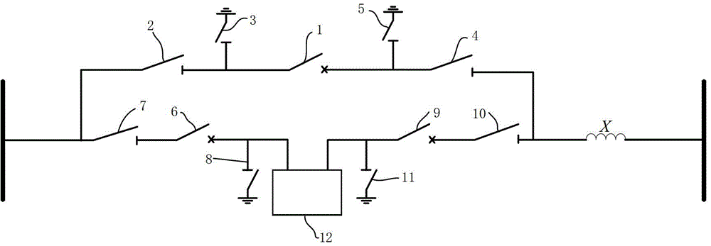
图2是本发明接入电力系统的结构图。Fig. 2 is a structural diagram of the present invention connected to the power system.
具体实施方式Detailed ways
以下将结合附图,对本发明的技术方案及有益效果进行详细说明。The technical solutions and beneficial effects of the present invention will be described in detail below in conjunction with the accompanying drawings.
如图2所示,本发明提供一种移相变压器系统,包括串联支路和并联支路,其中,串联支路串联在电力系统中输电线路的一端(送电侧或受电侧),而并联支路并联在串联支路的两端,X表示线路阻抗,下面分别介绍。As shown in Figure 2, the present invention provides a phase-shifting transformer system, including a series branch and a parallel branch, wherein the series branch is connected in series at one end of the transmission line (transmitting side or receiving side) in the power system, and The parallel branch is connected in parallel at both ends of the series branch, and X represents the line impedance, which will be introduced separately below.
所述串联支路包括依次串联的隔离刀闸7、断路器6、移相器本体12、断路器9和隔离刀闸10,还包括接地刀闸8、11,其中,接地刀闸8安装在断路器6与移相器本体12之间,接地刀闸11安装在移相器本体12和断路器9之间。The series branch includes an isolation switch 7, a circuit breaker 6, a phase shifter body 12, a circuit breaker 9 and an
所述并联支路包括依次串联的隔离刀闸2、旁路断路器1和隔离刀闸4,还包括接地刀闸3、5,其中,接地刀闸3安装在隔离刀闸2与旁路断路器1之间,接地刀闸5安装在旁路断路器1与隔离刀闸4之间,且旁路断路器1的合闸时间比常规断路器短。The parallel branch includes an
基于前述移相变压器系统,本发明还提供一种控制方法,具体包括以下内容:Based on the aforementioned phase-shifting transformer system, the present invention also provides a control method, specifically including the following:
(1)系统无故障正常运行时,定义系统包括运行、旁路、隔离、检修、旁路断路器检修五种运行状态,根据运行需求,通过对系统中断路器及刀闸的分合控制,实现对系统运行状态的控制,可结合表1所示,其中,I表示合,○表示分;(1) When the system is in normal operation without failure, the system is defined to include five operating states: operation, bypass, isolation, maintenance, and bypass circuit breaker maintenance. Realize the control to system running state, can combine as shown in table 1, and wherein, I represents to close, and ○ represents to divide;
表1Table 1
(a)运行态:旁路断路器1及接地刀闸3、5、8、11处于分位,断路器6、9及隔离刀闸7、10处于合位;此时移相器本体12投入运行,通过控制移相器本体12产生的补偿电压来改变输电线路两端之间的电压相角差,从而调节线路潮流;(a) Running state: Bypass circuit breaker 1 and
(b)旁路态:接地刀闸3、5、8、11处于分位,旁路断路器1、断路器6、9及隔离刀闸2、4、7、10处于合位;此时移相器本体12处于热备用状态,不对电力系统产生影响,随时可投入运行;(b) Bypass state:
(c)隔离态:旁路断路器1和隔离刀闸2、4处于合位,接地刀闸3、5、8、11,隔离刀闸7、10及断路器6、9均处于分位;此时移相器本体退出系统运行,但输电线路仍可正常投入运行;(c) Isolation state: Bypass circuit breaker 1 and
(d)检修态:旁路断路器1、隔离刀闸2、4及接地刀闸8、11处于合位,接地刀闸3、5,隔离刀闸7、10及断路器6、9处于分位;此时移相器本体12已退出系统,可对移相器本体12及其控制保护系统进行检修,串联支路中的隔离刀闸7、10为检修人员提供明显的断点,接地刀闸8、11保证移相器本体12的可靠接地;(d) Inspection state: bypass circuit breaker 1,
(e)旁路断路器检修态:旁路断路器1、隔离刀闸2、4及接地刀闸8、11处于分位,接地刀闸3、5,隔离刀闸7、10及断路器6、9处于合位;此时移相器本体12投入系统运行,并联支路中的隔离刀闸2、5为检修人员提供明显的断点,接地刀闸3、5保证旁路断路器1的可靠接地。(e) Inspection state of bypass circuit breaker: bypass circuit breaker 1, isolation switches 2 and 4, and
(2)系统发生故障时,若故障为移相器本体内部故障,如匝间短路、瓦斯故障等,断开串联支路中的断路器6、9并闭合并联支路中的旁路断路器1,将移相器本体12从输电线路中完全隔离出来,缩小故障范围,且不影响输电线路的正常运行;例如,若在运行或旁路状态下移相器本体发生故障,可通过闭合旁路断路器1,断开断路器6、9及隔离刀闸7、10切换为隔离态;若需要对设备进行检修,可再闭合接地刀闸8、11,切换至检修态;(2) When the system fails, if the fault is an internal fault of the phase shifter body, such as inter-turn short circuit, gas fault, etc., disconnect the circuit breakers 6 and 9 in the series branch and close the bypass circuit breaker in the parallel branch 1. Completely isolate the phase shifter body 12 from the power transmission line to reduce the fault range without affecting the normal operation of the power transmission line; Circuit breaker 1, disconnect circuit breakers 6, 9 and
若故障为移相器本体外的故障,如安装移相器本体的线路发生故障,将并联支路中的旁路断路器1闭合,暂时将移相器本体置于旁路热备用状态,待外部故障切除后,是否断开旁路断路器1将移相器本体12重新投入,可由控制保护系统中的控制字来整定。If the fault is outside the phase shifter body, such as the line where the phase shifter body is installed fails, close the bypass circuit breaker 1 in the parallel branch, temporarily put the phase shifter body in the bypass hot standby state, and wait for After the external fault is removed, whether to disconnect the bypass circuit breaker 1 and reconnect the phase shifter body 12 can be set by the control word in the control and protection system.
最后应该说明的是:结合上述实施例仅说明本发明的技术方案而非对其限制。所属领域的普通技术人员应当理解到:本领域技术人员可以对本发明的具体实施方式进行修改或者等同替换,但这些修改或变更均在申请待批的专利要求保护范围之内。Finally, it should be noted that: the combination of the above embodiments only illustrates the technical solution of the present invention rather than limiting it. Those of ordinary skill in the art should understand that: those skilled in the art can modify or equivalently replace the specific embodiments of the present invention, but these modifications or changes are all within the protection scope of the pending patent application.
Claims (4)
Priority Applications (1)
| Application Number | Priority Date | Filing Date | Title |
|---|---|---|---|
| CN201310354188.5A CN103427426B (en) | 2013-08-14 | 2013-08-14 | Phase-shifting transformer system and control method thereof |
Applications Claiming Priority (1)
| Application Number | Priority Date | Filing Date | Title |
|---|---|---|---|
| CN201310354188.5A CN103427426B (en) | 2013-08-14 | 2013-08-14 | Phase-shifting transformer system and control method thereof |
Publications (2)
| Publication Number | Publication Date |
|---|---|
| CN103427426A true CN103427426A (en) | 2013-12-04 |
| CN103427426B CN103427426B (en) | 2015-04-08 |
Family
ID=49651797
Family Applications (1)
| Application Number | Title | Priority Date | Filing Date |
|---|---|---|---|
| CN201310354188.5A Active CN103427426B (en) | 2013-08-14 | 2013-08-14 | Phase-shifting transformer system and control method thereof |
Country Status (1)
| Country | Link |
|---|---|
| CN (1) | CN103427426B (en) |
Cited By (3)
| Publication number | Priority date | Publication date | Assignee | Title |
|---|---|---|---|---|
| CN105119294A (en) * | 2015-10-08 | 2015-12-02 | 南京南瑞继保电气有限公司 | Power-adjustable moving die system |
| CN113937887A (en) * | 2021-10-12 | 2022-01-14 | 西安热工研究院有限公司 | Phase shifter loop closing thermal inversion control method and system |
| CN114447929A (en) * | 2022-02-18 | 2022-05-06 | 广东电网有限责任公司 | Phase shifting device and control method thereof |
Citations (3)
| Publication number | Priority date | Publication date | Assignee | Title |
|---|---|---|---|---|
| WO2008023141A1 (en) * | 2006-08-24 | 2008-02-28 | Rolls-Royce Plc | Electrical distribution networks |
| CN102279325A (en) * | 2011-04-19 | 2011-12-14 | 中国电力科学研究院 | Ultra high voltage direct current (UHVDC) transmission engineering station system debugging method |
| CN102540001A (en) * | 2012-02-16 | 2012-07-04 | 云南电网公司 | Method of checking alternating current loop of a 500kV transformer substation through carrying out simulated through-type three-phase short circuit |
-
2013
- 2013-08-14 CN CN201310354188.5A patent/CN103427426B/en active Active
Patent Citations (3)
| Publication number | Priority date | Publication date | Assignee | Title |
|---|---|---|---|---|
| WO2008023141A1 (en) * | 2006-08-24 | 2008-02-28 | Rolls-Royce Plc | Electrical distribution networks |
| CN102279325A (en) * | 2011-04-19 | 2011-12-14 | 中国电力科学研究院 | Ultra high voltage direct current (UHVDC) transmission engineering station system debugging method |
| CN102540001A (en) * | 2012-02-16 | 2012-07-04 | 云南电网公司 | Method of checking alternating current loop of a 500kV transformer substation through carrying out simulated through-type three-phase short circuit |
Cited By (4)
| Publication number | Priority date | Publication date | Assignee | Title |
|---|---|---|---|---|
| CN105119294A (en) * | 2015-10-08 | 2015-12-02 | 南京南瑞继保电气有限公司 | Power-adjustable moving die system |
| CN113937887A (en) * | 2021-10-12 | 2022-01-14 | 西安热工研究院有限公司 | Phase shifter loop closing thermal inversion control method and system |
| CN114447929A (en) * | 2022-02-18 | 2022-05-06 | 广东电网有限责任公司 | Phase shifting device and control method thereof |
| CN114447929B (en) * | 2022-02-18 | 2025-04-22 | 广东电网有限责任公司 | Phase shifting device and control method thereof |
Also Published As
| Publication number | Publication date |
|---|---|
| CN103427426B (en) | 2015-04-08 |
Similar Documents
| Publication | Publication Date | Title |
|---|---|---|
| CN110350651B (en) | Spare power automatic switching misoperation prevention method for 110kV single bus faults | |
| CN103618329B (en) | Multi-terminal flexible direct current transmission system and its single station online isolation and grid connection method | |
| CN107370130B (en) | A hybrid HVDC circuit breaker based on improved half-bridge sub-module and its control strategy | |
| CN104467163A (en) | Fragmented spare power automatic switching implementation method for multiple power incoming lines | |
| CN101710731B (en) | Control method of concentrated standby power automatic transfer system | |
| CN110994623B (en) | A 10kV superconducting ring closing operation method | |
| CN103427426B (en) | Phase-shifting transformer system and control method thereof | |
| CN202940470U (en) | Double-bus wiring system | |
| CN103296692A (en) | Control device and method for putting converter station into flexible direct current power transmission system | |
| CN103227468B (en) | Main wiring pairing and stringing optimization method for transformer station | |
| CN110277771B (en) | A method for improving the breaking capacity of short-circuit current in substations by means of line T-connection | |
| CN202221921U (en) | Transformer station standby power automatic switching system having open-phase protection function | |
| CN204835226U (en) | Line arrangement structure of two complete clusters is joined in marriage into in wiring of one and half circuit breakers | |
| CN107579593B (en) | Energy supply system of high-voltage direct-current circuit breaker | |
| CN202009236U (en) | Single-bus segmental running control device of substation | |
| CN109004660B (en) | Intelligent load distributor for intelligent camera changing mechanism | |
| CN112564119A (en) | Load transfer system control method and device | |
| CN207853185U (en) | The female simultaneous other system structure of substation | |
| CN103986159B (en) | There is the mounting circuit of THE UPFC in multi transformer station | |
| CN207459723U (en) | Spare phase transformer quickly puts into arrangement | |
| CN103746354B (en) | One kind is based on transformer station's overcurrent protection method for isolating power distribution network fault without constant time lag in | |
| CN110783915A (en) | Multi-distribution-platform-area power supply method and power supply system | |
| CN211017992U (en) | Multiport direct current breaker maintenance system that does not have a power failure | |
| CN103956743B (en) | A kind of 10KV power distribution network optimization method based on phase difference and device | |
| CN202405853U (en) | 110-KV double-circuit parallel running line reclosing input line |
Legal Events
| Date | Code | Title | Description |
|---|---|---|---|
| C06 | Publication | ||
| PB01 | Publication | ||
| C10 | Entry into substantive examination | ||
| SE01 | Entry into force of request for substantive examination | ||
| C14 | Grant of patent or utility model | ||
| GR01 | Patent grant |