CN103422740A - Mechanical lock - Google Patents
Mechanical lock Download PDFInfo
- Publication number
- CN103422740A CN103422740A CN2013103529347A CN201310352934A CN103422740A CN 103422740 A CN103422740 A CN 103422740A CN 2013103529347 A CN2013103529347 A CN 2013103529347A CN 201310352934 A CN201310352934 A CN 201310352934A CN 103422740 A CN103422740 A CN 103422740A
- Authority
- CN
- China
- Prior art keywords
- lock
- cover plate
- block
- latch hook
- hook
- Prior art date
- Legal status (The legal status is an assumption and is not a legal conclusion. Google has not performed a legal analysis and makes no representation as to the accuracy of the status listed.)
- Granted
Links
Images


Landscapes
- Underground Structures, Protecting, Testing And Restoring Foundations (AREA)
- Automatic Focus Adjustment (AREA)
- Optical Recording Or Reproduction (AREA)
Abstract
本发明涉及锁技术领域,尤指一种机械锁,包括面壳和底壳,面壳和底壳固定连接,面壳设有拉链插孔,面壳和底壳内部形成一容纳空间,所述容纳空间安装有盖板和开闭锁机构,所述开闭锁机构包括活动块、第一锁钩以及可控制第一锁钩开合的第一锁块,所述容纳空间还安装有可推动活动块沿盖板滑动的推动机构;针对现有技术中机械锁结构复杂、体积较大的问题,本发明提供了一种机械锁,其结构简单,体积较小,并且可以通过推动机构的左右滑动分别控制四个锁钩的开合,操作方便。
The invention relates to the technical field of locks, in particular to a mechanical lock, which includes a face shell and a bottom shell, the face shell and the bottom shell are fixedly connected, the face shell is provided with a zipper hole, and an accommodation space is formed inside the face shell and the bottom shell. The accommodating space is equipped with a cover plate and an opening and closing mechanism. The opening and closing mechanism includes a movable block, a first locking hook, and a first locking block that can control the opening and closing of the first locking hook. The accommodating space is also equipped with a movable block that can be pushed. A push mechanism that slides along the cover plate; aiming at the problem of complex structure and large volume of mechanical locks in the prior art, the present invention provides a mechanical lock with a simple structure and small volume, and can be separated by sliding left and right of the push mechanism. Control the opening and closing of the four lock hooks, easy to operate.
Description
技术领域 technical field
本发明涉及锁技术领域,尤指一种机械锁。 The present invention relates to the technical field of locks, in particular to a mechanical lock.
背景技术 Background technique
现有的箱包为了防止他人随意打开,一般是在箱包的箱体设置有锁钩,箱盖设置有拉链,锁钩打开时,箱包处于开锁状态;当需要上锁时,将拉链伸入所述锁钩内,并闭合锁钩,如果锁钩没有解锁,拉链是无法从锁钩内脱扣的,即箱盖无法打开。 In order to prevent other people from opening the existing bags at will, the casing of the bag is generally provided with a lock hook, and the cover is provided with a zipper. When the lock hook is opened, the bag is in an unlocked state; If the lock hook is not unlocked, the zipper cannot be released from the lock hook, that is, the box cover cannot be opened.
目前市场上用于箱包的机械锁种类繁多,但大多结构复杂,体积较大。 There are many types of mechanical locks used for luggage on the market, but most of them have complex structures and large volumes.
发明内容 Contents of the invention
针对现有技术中机械锁结构复杂、体积较大的问题,本发明提供了一种机械锁,其结构简单,体积较小。 Aiming at the problem of complex structure and large volume of mechanical locks in the prior art, the present invention provides a mechanical lock with simple structure and small volume.
为达到以上目的,本发明机械锁主要采用以下技术方案: In order to achieve the above purpose, the mechanical lock of the present invention mainly adopts the following technical solutions:
一种机械锁,包括面壳和底壳,面壳和底壳固定连接,面壳设有拉链插孔,面壳和底壳内部形成一容纳空间,所述容纳空间安装有盖板和开闭锁机构,所述开闭锁机构包括活动块、第一锁钩以及可控制第一锁钩开合的第一锁块,活动块与盖板滑动连接,第一锁钩与盖板铰接,盖板设有可与第一锁块滑动连接的第一滑槽,活动块设有第一直斜面,第一锁块设有可与第一直斜面滑动连接的第二直斜面,第一锁块与盖板之间抵接有第一复位弹簧,所述容纳空间还安装有可推动活动块沿盖板滑动的推动机构。 A mechanical lock, comprising a face shell and a bottom shell, the face shell and the bottom shell are fixedly connected, the face shell is provided with a zipper jack, and an accommodation space is formed inside the face shell and the bottom shell, and a cover plate and an opening and closing lock are installed in the accommodation space mechanism, the opening and closing locking mechanism includes a movable block, a first lock hook and a first lock block that can control the opening and closing of the first lock hook, the movable block is slidingly connected with the cover plate, the first lock hook is hinged with the cover plate, and the cover plate is provided There is a first chute that can be slidably connected with the first lock block, the movable block is provided with a first straight slope, the first lock block is provided with a second straight slope that can be slidably connected with the first straight slope, the first lock block and the cover A first return spring is abutted between the plates, and a pushing mechanism that can push the movable block to slide along the cover plate is installed in the accommodation space.
优选的,所述开闭锁机构的数量为两个,两个开闭锁机构左右对称设置于推动机构的两侧。 Preferably, there are two opening and closing mechanisms, and the two opening and closing mechanisms are symmetrically arranged on both sides of the pushing mechanism.
优选的,所述推动机构包括离合块和锁芯,离合块设有第一凸起,锁芯设有可与离合块的第一凸起卡接的卡槽,锁芯与活动块抵触连接,离合块与盖板滑动连接,离合块设有限位板,盖板设有限位柱,当离合块旋转到闭锁状态时,限位柱抵顶限位板。 Preferably, the pushing mechanism includes a clutch block and a lock core, the clutch block is provided with a first protrusion, the lock core is provided with a slot that can engage with the first protrusion of the clutch block, and the lock core is in conflicting connection with the movable block, The clutch block is slidingly connected with the cover plate, the clutch block is provided with a limit plate, and the cover plate is provided with a limit post. When the clutch block rotates to the locked state, the limit post pushes against the limit plate.
优选的,所述开闭锁机构还包括第二锁钩以及可控制第二锁钩开合的第二锁块,第二锁钩与盖板铰链连接,盖板设有可与第二锁块滑动连接的第二滑槽,所述活动块设有第三直斜面,第二锁块设有可与第三直斜面滑动连接的第四直斜面,第二锁块与盖板之间抵接有第二复位弹簧。 Preferably, the opening and closing locking mechanism further includes a second lock hook and a second lock block that can control the opening and closing of the second lock hook, the second lock hook is hingedly connected to the cover plate, and the cover plate is provided with a sliding door that can slide with the second lock block connected to the second chute, the movable block is provided with a third straight slope, the second lock block is provided with a fourth straight slope that can be slidably connected with the third straight slope, and the second lock block is in contact with the cover plate with a Second return spring.
优选的,所述第一锁钩设有挡板,闭锁时,第一锁块抵顶所述挡板。 Preferably, the first lock hook is provided with a baffle, and when locked, the first lock block abuts against the baffle.
另一优选的,所述第一锁钩设有固定板,第一锁块设有另一卡槽,另一卡槽的两端均设有可供固定板滑入和滑出的开口,闭锁时,所述固定板与另一卡槽卡接。 Another preferred feature is that the first locking hook is provided with a fixing plate, the first locking block is provided with another card slot, and the two ends of the other card slot are provided with openings for sliding in and out of the fixing plate, and the locking , the fixing plate is snapped into another slot.
优选的,所述机械锁包括销轴,第一锁钩与盖板通过销轴铰接。 Preferably, the mechanical lock includes a pin shaft, and the first lock hook and the cover plate are hinged through the pin shaft.
优选的,所述销轴设有定位柱,定位柱的两端分别抵顶锁钩和盖板。 Preferably, the pin shaft is provided with a positioning column, and the two ends of the positioning column respectively abut against the lock hook and the cover plate.
优选的,所述销轴与第一锁钩固定连接,销轴设有第二凸起,盖板设有可限制第二凸起旋转角度的限位槽。 Preferably, the pin shaft is fixedly connected with the first locking hook, the pin shaft is provided with a second protrusion, and the cover plate is provided with a limiting slot capable of limiting the rotation angle of the second protrusion.
优选的,所述销轴外侧套设有扭簧,扭簧的两端分别与盖板和第一锁钩固定连接。 Preferably, a torsion spring is sleeved on the outer side of the pin shaft, and two ends of the torsion spring are fixedly connected to the cover plate and the first locking hook respectively.
本发明机械锁的有益效果为:所述推动机构推动活动块沿盖板滑动,第一锁块在活动块和第一复位弹簧的作用下沿第一滑槽来回滑动,当第一锁块滑动至第一滑槽的一端时,第一锁块控制锁钩开锁,当第一锁块滑动至第一滑槽的另一端时,第一锁块控制锁钩闭锁,通过该种方式实现本发明的开锁和闭锁,其结构简单,控制方便;另外,本发明机械锁利用多个斜面将推力进行传递,实现开闭锁状态的切换,节省了空间,从而使本发明机械锁的体积较小。 The beneficial effects of the mechanical lock of the present invention are: the pushing mechanism pushes the movable block to slide along the cover plate, the first locking block slides back and forth along the first slide groove under the action of the movable block and the first return spring, when the first locking block slides When reaching one end of the first chute, the first lock block controls the lock hook to unlock, and when the first lock block slides to the other end of the first chute, the first lock block controls the lock hook to lock, in this way the present invention is realized In addition, the mechanical lock of the present invention uses a plurality of slopes to transmit the thrust to realize switching between the unlocked and locked states, which saves space and makes the mechanical lock of the present invention smaller in size.
附图说明 Description of drawings
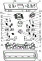
图1是本发明机械锁实施例一的分解结构示意图。
Fig. 1 is a schematic diagram of an exploded structure of
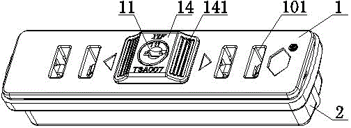
图2是本发明机械锁实施例一的结构示意图。
Fig. 2 is a schematic structural view of
图3是本发明机械锁实施例一隐去面壳和底壳后的剖面结构示意图。 Fig. 3 is a schematic cross-sectional structural view of the first embodiment of the mechanical lock of the present invention with the face shell and the bottom shell hidden.
图4是本发明机械锁实施例一的盖板的结构示意图。
Fig. 4 is a schematic structural view of the cover plate of
图5是本发明机械锁实施例一的离合块的结构示意图。
Fig. 5 is a schematic structural view of the clutch block in
图6是本发明机械锁实施例一的活动块的结构示意图。
Fig. 6 is a schematic structural view of the movable block of
图7是本发明机械锁实施例一的第一锁块的结构示意图。
Fig. 7 is a schematic structural view of the first lock block in
图8是本发明机械锁实施例一的第二锁块的结构示意图。
Fig. 8 is a schematic structural view of the second lock block of
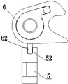
图9是本发明机械锁实施例二的第一锁钩与第一锁块连接的结构示意图。 Fig. 9 is a schematic structural diagram of the connection between the first locking hook and the first locking block in the second embodiment of the mechanical lock of the present invention.
具体实施方式 Detailed ways
实施例一。 Embodiment one.
如图1~图8所示,一种机械锁,包括面壳1和底壳2,面壳1和底壳2固定连接,面壳1设有拉链插孔101,面壳1和底壳2内部形成一容纳空间,所述容纳空间安装有盖板3和开闭锁机构,所述开闭锁机构包括活动块4、第一锁钩6以及可控制第一锁钩6开合的第一锁块5,活动块4与盖板3滑动连接,第一锁钩6与盖板3铰接,第一锁钩6可相对盖板3旋转,当第一锁钩6旋转到不同的位置时可分别处于打开和闭合两种不同的状态,盖板3设有可与第一锁块5滑动连接的第一滑槽32,第一滑槽32限定第一锁块5的滑动范围,使第一锁块5只能沿第一滑槽32的范围进行滑动,活动块4设有第一直斜面41,第一锁块5设有可与第一直斜面41滑动连接的第二直斜面51,第一锁块5与盖板3之间抵接有第一复位弹簧15,所述容纳空间还安装有可推动活动块4沿盖板3滑动的推动机构。具体的,在开锁时,推动推动机构,活动块4在推动机构的驱使下向一侧滑动,第一锁块5上的第二直斜面51与活动块4的第一直斜面41相互配合,第一锁块5在活动块4的带动下沿第一滑槽32滑动,当第一锁块5沿第一滑槽32滑动至开锁位置时,第一锁块5控制第一锁钩6打开,此时拉链可以从第一锁钩6内取出,从而实现本发明机械锁的开锁;在闭锁时,将拉链插入第一锁钩6,拉链带动第一锁钩6闭合,第一锁块5在第一复位弹簧15的作用下沿第一滑槽32滑至闭锁位置,第一锁块5控制第一锁钩6将拉链锁死,从而实现本发明的闭锁。其中,所述推动机构推动活动块4沿盖板3滑动,第一锁块5在活动块4和第一复位弹簧15的作用下沿第一滑槽32来回滑动,当第一锁块5滑动至第一滑槽32的一端时,第一锁块5控制锁钩开锁,当第一锁块5滑动至第一滑槽32的另一端时,第一锁块5控制锁钩闭锁,通过该种方式实现本发明的开锁和闭锁,其结构简单,控制方便;另外,本发明机械锁利用多个斜面将推力进行传递,实现开闭锁状态的切换,节省了空间,从而使本发明机械锁的体积较小。
As shown in Figures 1 to 8, a mechanical lock includes a
所述推动机构包括离合块13和锁芯11,离合块13设有第一凸起131,锁芯11设有可与离合块13的第一凸起131卡接的卡槽111,离合块13通过设置的第一凸起131与锁芯11卡接,锁芯11与活动块4抵触连接,离合块13与盖板3滑动连接,离合块13设有限位板132,盖板3设有限位柱31,当离合块13旋转到闭锁状态时,限位柱31抵顶限位板132。具体的,在闭锁状态时,离合块13上的限位板132抵顶盖板3上的限位柱31,盖板3上的限位柱31限制离合块13沿盖板3不能左右滑动;当需要开锁时,用钥匙拧动锁芯11,锁芯11带动离合块13一起旋转,直至离合块13上的限位板132与盖板3的限位柱31脱离,盖板3的限位柱31对离合块13的阻挡干涉随之消失,离合块13又可以随锁芯11一起沿盖板3左右滑动,此时,推动锁芯11时,锁芯11带动活动块4沿盖板3向一侧滑动。通过设置的锁芯11和离合块13来实现推动活动块4沿盖板3滑动的功能,其结构简单,控制方便,另外,需要使用钥匙对锁芯11开锁,增强了本发明的安全使用性能。
The pushing mechanism includes a
所述锁芯11的外侧套设有锁芯套12,通过设置的锁芯套12,对锁芯11进行保护,能够有效防止锁芯11由于意外碰撞而发生损伤,同时也方便了使用者的操作,提高了本发明的实用性能。
The outer cover of the
所述锁芯11外侧还套设有推动块14,通过设置的推动块14,既可以对锁芯11进行有效的保护,同时也方便了使用者对锁芯11的左右推动。
The outer side of the
所述推动块14设有防滑纹141,通过设置的防滑纹141,提高了推动块14表面的粗糙度,增大了手指与推动块14接触时的摩擦力,方便了使用者对推动块14的左右推动。
The
所述第一锁钩6设有挡板61,闭锁时,第一锁块5抵顶所述挡板61,具体的,在初始闭锁状态时,第一锁块5抵顶第一锁钩6的挡板61,第一锁块5对第一锁钩6的位置进行限定,并使第一锁钩6处于闭合状态;当需要开锁时,推动推动机构,推动机构带动活动块4沿盖板3向一侧滑动,活动块4推动第一锁块5沿第一滑槽32滑动,当第一锁块5滑动至开锁位置时,第一锁钩6上的挡板61与第一锁块5脱离,第一锁块5对第一锁钩6的阻挡干涉随之消失,第一锁钩6又可以自由的旋转至打开位置,从而第一锁块5控制第一锁钩6打开,本发明处于开锁状态;闭锁时,将拉链插入拉链插孔101,拉链带动第一锁钩6闭合,第一锁块5在第一复位弹簧15的作用下沿第一滑槽32滑至闭锁位置,第一锁块5又抵顶第一锁钩6的挡板61,从而第一锁块5控制第一锁钩6闭合,本发明处于闭锁状态;通过在第一锁钩6设置挡板61,第一锁块5控制第一锁钩6的开合,从而进一步的控制本发明的开锁和闭锁,其结构简单,控制方便。
The
所述开闭锁机构的数量为两个,两个开闭锁机构左右对称设置于推动机构的两侧。具体的,两个开闭锁机构的结构特征基本相同,当推动机构向左滑动时,推动机构可推动左侧的开闭锁机构的活动块4沿盖板3滑动,活动块4进一步的带动第一锁块5实现对第一锁钩6的开锁;当推动机构向右滑动时,推动机构可推动右侧的开闭锁机构的活动块4沿盖板3滑动,右侧的活动块4带动锁块实现对锁钩的开锁;其中,活动块4控制本发明开锁的过程在前面已有阐述,在此不再赘述。通过设置的两个开闭锁机构,增加了锁钩的数量,可以对箱包上的多个拉链同时进行上锁,增强了本发明的安全性能和实用性能;另外,在本实施例中,通过推动锁芯左右滑动,即可分别控制两侧的锁块对锁钩的开锁,一个锁芯可分别控制多个锁钩的开合,其结构简单,操作方便。
There are two opening and closing mechanisms, and the two opening and closing mechanisms are symmetrically arranged on both sides of the pushing mechanism. Specifically, the structural features of the two opening and closing locking mechanisms are basically the same. When the pushing mechanism slides to the left, the pushing mechanism can push the
所述开闭锁机构还包括第二锁钩8以及可控制第二锁钩8开合的第二锁块7,第二锁钩8与盖板3铰链连接,盖板3设有可与第二锁块7滑动连接的第二滑槽33,所述活动块4设有第三直斜面42,第二锁块7设有可与第三直斜面42滑动连接的第四直斜面71,第二锁块7与盖板3之间抵接有第二复位弹簧16。该第二锁钩8与第二锁块7之间的工作原理跟第一锁钩6与第一锁块5之间的工作原理相同,第一锁钩6与第一锁块5之间的工作原理在前面已有阐述,在此不再赘述,通过设置的第二锁钩8与第二锁块7以及第一锁钩6与第一锁块5同时工作,可以满足某些物件需要两个锁钩才能锁住的情形,为消费者提供了多种选择,提高了本发明机械锁的实用性能。
The opening and closing locking mechanism also includes a
所述机械锁包括销轴9,第一锁钩6与盖板3通过销轴9铰接,通过设置的销轴9,方便了零部件的加工,同时当单个零件发生损坏时可以随时更换。
The mechanical lock includes a pin shaft 9, the
所述销轴9设有定位柱92,定位柱92的两端分别抵顶第一锁钩6和盖板3,通过设置的定位柱92,可以对第一锁钩6在销轴9上的位置进行定位,使第一锁钩6可以准确的安装于预设的位置,同时也提高了第一锁钩6安装时的装配效率,增强了本发明密码锁的实用性能。
The bearing pin 9 is provided with a positioning column 92, and the two ends of the positioning column 92 respectively abut against the
所述销轴9与第一锁钩6固定连接,销轴9设有第二凸起91,盖板3设有可限制第二凸起91旋转角度的限位槽34,具体的,销轴9与第一锁钩6过盈配合,销轴9可与第一锁钩6一起转动,通过在盖板3上设置的限位槽34,限位槽34限制第二凸起91在0~90度的范围内旋转,通过设置的限位槽34限制第一锁钩6在0~90度的工作范围内旋转,减少了第一锁钩6在其他方向无意义的旋转,使第一锁钩6在工作时可以快速的旋转至打开和闭合的位置,增强了本发明密码锁的实用性能。
The pin shaft 9 is fixedly connected with the
所述销轴9外侧套设有扭簧10,扭簧10的两端分别与盖板3和第一锁钩6固定连接。具体的,第一锁钩6与盖板3通过销轴9铰链连接,第一锁钩6可相对盖板3转动,通过安装的扭簧10,第一锁钩6在扭簧10的作用下可自动旋转至打开状态,其结构简单,提高了本发明密码锁的实用性能。
A
所述盖板3设有可对活动块4的位置进行定位的另一限位柱35,另一限位柱35设有定位槽,通过在另一限位柱35上设置定位槽,限制活动块4只能沿水平方向左右滑动,能够对活动块4的位置进行准确的定位,并可对活动块4的滑动进行导向,提高了活动块4的运动精度。
Described
实施例二。 Embodiment two.
本实施例的技术方案与实施例一的技术方案基本相同,其区别在于: The technical solution of the present embodiment is basically the same as the technical solution of the first embodiment, the difference is:
如图9所示,所述第一锁钩6设有固定板62,第一锁块5设有另一卡槽52,另一卡槽52的两端均设有可供固定板62滑入和滑出的开口,闭锁时,所述固定板62与另一卡槽52卡接。具体的,在初始闭锁状态时,第一锁钩6的固定板62卡入第一锁块5的另一卡槽52,第一锁钩6与第一锁块5卡接,第一锁块5对第一锁钩6的位置进行限定,并使第一锁钩6处于闭合状态;当需要开锁时,推动推动机构,推动机构带动活动块4沿盖板3向一侧滑动,活动块4推动第一锁块5沿第一滑槽32滑动,当第一锁块5滑动至开锁位置时,第一锁钩6的固定板62也随之从第一锁块5的另一卡槽52的开口滑出,第一锁块5对第一锁钩6的阻挡干涉随之消失,第一锁钩6又可以自由的旋转至打开位置,从而第一锁块5控制第一锁钩6打开,本发明处于开锁状态;闭锁时,将拉链插入拉链插孔101,拉链带动第一锁钩6闭合,第一锁块5在第一复位弹簧15的作用下沿第一滑槽32滑至闭锁位置,第一锁钩6上的固定板62也沿另一卡槽52的开口滑入,第一锁钩6的固定板62与第一锁块5的另一卡槽52卡接,从而第一锁块5控制第一锁钩6闭合,本发明处于闭锁状态;通过设置的固定板62和另一卡槽52,第一锁块5控制第一锁钩6的开合,从而进一步的控制本发明的开锁和闭锁,其结构简单,控制方便。
As shown in Figure 9, the
本实施例的主要技术方案与实施例一相同,在本实施例中未解释的特征,采用实施例一中的解释,在此不再赘述。
The main technical solution of this embodiment is the same as that of
以上所述实施方式,只是本发明的较佳实施方式,并非来限制本发明实施范围,故凡依本发明申请专利范围所述的构造、特征及原理所做的等效变化或修饰,均应包括在本发明专利申请范围内。 The above-described embodiments are only preferred embodiments of the present invention, and are not intended to limit the scope of the present invention, so all equivalent changes or modifications made according to the structure, features and principles described in the patent scope of the present invention should be Included in the patent application scope of the present invention.
Claims (10)
Priority Applications (2)
| Application Number | Priority Date | Filing Date | Title |
|---|---|---|---|
| CN201310352934.7A CN103422740B (en) | 2013-05-31 | 2013-08-14 | Mechanical lock |
| JP2014002863U JP3192534U (en) | 2013-05-31 | 2014-06-01 | Mechanical lock |
Applications Claiming Priority (4)
| Application Number | Priority Date | Filing Date | Title |
|---|---|---|---|
| CN201320309107 | 2013-05-31 | ||
| CN2013203091075 | 2013-05-31 | ||
| CN201320309107.5 | 2013-05-31 | ||
| CN201310352934.7A CN103422740B (en) | 2013-05-31 | 2013-08-14 | Mechanical lock |
Publications (2)
| Publication Number | Publication Date |
|---|---|
| CN103422740A true CN103422740A (en) | 2013-12-04 |
| CN103422740B CN103422740B (en) | 2016-08-17 |
Family
ID=49648078
Family Applications (2)
| Application Number | Title | Priority Date | Filing Date |
|---|---|---|---|
| CN201320494545.3U Expired - Lifetime CN203441212U (en) | 2013-05-31 | 2013-08-14 | Mechanical lock |
| CN201310352934.7A Active CN103422740B (en) | 2013-05-31 | 2013-08-14 | Mechanical lock |
Family Applications Before (1)
| Application Number | Title | Priority Date | Filing Date |
|---|---|---|---|
| CN201320494545.3U Expired - Lifetime CN203441212U (en) | 2013-05-31 | 2013-08-14 | Mechanical lock |
Country Status (2)
| Country | Link |
|---|---|
| JP (1) | JP3192534U (en) |
| CN (2) | CN203441212U (en) |
Cited By (5)
| Publication number | Priority date | Publication date | Assignee | Title |
|---|---|---|---|---|
| CN103938948A (en) * | 2014-04-22 | 2014-07-23 | 东莞市怡丰锁业有限公司 | Mechanical lock |
| CN103993789A (en) * | 2014-05-06 | 2014-08-20 | 中山可锁五金塑料制品有限公司 | Remote control case and bag zip fastener lock |
| CN109458067A (en) * | 2018-12-27 | 2019-03-12 | 浙江聚盛电气有限公司 | The door lock mechanism of switchgear |
| CN110185324A (en) * | 2019-06-17 | 2019-08-30 | 东莞市景瑜实业有限公司 | A kind of puzzle lock for zipper for multilayer luggage |
| CN110185337A (en) * | 2019-06-28 | 2019-08-30 | 东莞市景瑜实业有限公司 | A kind of sunk type zipper lock |
Families Citing this family (5)
| Publication number | Priority date | Publication date | Assignee | Title |
|---|---|---|---|---|
| CN203441212U (en) * | 2013-05-31 | 2014-02-19 | 东莞市怡丰锁业有限公司 | Mechanical lock |
| CN106050014B (en) * | 2016-08-01 | 2018-05-22 | 东莞市怡丰锁业有限公司 | Double-zipper lock |
| CN111852185B (en) * | 2020-08-05 | 2024-09-17 | 中山市基信锁芯有限公司 | A smart lock |
| TWI848659B (en) * | 2023-04-12 | 2024-07-11 | 競泰股份有限公司 | Multi-directional lock and luggage with the same |
| CN116905903A (en) * | 2023-08-07 | 2023-10-20 | 胡世忠 | Electric control clutch lock core for automatic lock |
Citations (5)
| Publication number | Priority date | Publication date | Assignee | Title |
|---|---|---|---|---|
| CN202596354U (en) * | 2012-04-01 | 2012-12-12 | 中山可锁五金塑料制品有限公司 | Double-sided zipper lock |
| US20130036778A1 (en) * | 2011-08-08 | 2013-02-14 | The Sun Lock Company, Ltd. | Dual locking system for integrated zipper lock |
| CN202745542U (en) * | 2012-07-20 | 2013-02-20 | 金泰祥精密五金(昆山)有限公司 | Embedded bag lock |
| CN202866466U (en) * | 2012-09-28 | 2013-04-10 | 东莞市怡丰锁业有限公司 | A kind of bag zipper composite lock |
| CN203441212U (en) * | 2013-05-31 | 2014-02-19 | 东莞市怡丰锁业有限公司 | Mechanical lock |
-
2013
- 2013-08-14 CN CN201320494545.3U patent/CN203441212U/en not_active Expired - Lifetime
- 2013-08-14 CN CN201310352934.7A patent/CN103422740B/en active Active
-
2014
- 2014-06-01 JP JP2014002863U patent/JP3192534U/en not_active Expired - Lifetime
Patent Citations (5)
| Publication number | Priority date | Publication date | Assignee | Title |
|---|---|---|---|---|
| US20130036778A1 (en) * | 2011-08-08 | 2013-02-14 | The Sun Lock Company, Ltd. | Dual locking system for integrated zipper lock |
| CN202596354U (en) * | 2012-04-01 | 2012-12-12 | 中山可锁五金塑料制品有限公司 | Double-sided zipper lock |
| CN202745542U (en) * | 2012-07-20 | 2013-02-20 | 金泰祥精密五金(昆山)有限公司 | Embedded bag lock |
| CN202866466U (en) * | 2012-09-28 | 2013-04-10 | 东莞市怡丰锁业有限公司 | A kind of bag zipper composite lock |
| CN203441212U (en) * | 2013-05-31 | 2014-02-19 | 东莞市怡丰锁业有限公司 | Mechanical lock |
Cited By (7)
| Publication number | Priority date | Publication date | Assignee | Title |
|---|---|---|---|---|
| CN103938948A (en) * | 2014-04-22 | 2014-07-23 | 东莞市怡丰锁业有限公司 | Mechanical lock |
| CN103938948B (en) * | 2014-04-22 | 2017-01-04 | 东莞市怡丰锁业有限公司 | Mechanical lock |
| CN103993789A (en) * | 2014-05-06 | 2014-08-20 | 中山可锁五金塑料制品有限公司 | Remote control case and bag zip fastener lock |
| CN109458067A (en) * | 2018-12-27 | 2019-03-12 | 浙江聚盛电气有限公司 | The door lock mechanism of switchgear |
| CN110185324A (en) * | 2019-06-17 | 2019-08-30 | 东莞市景瑜实业有限公司 | A kind of puzzle lock for zipper for multilayer luggage |
| CN110185324B (en) * | 2019-06-17 | 2024-03-15 | 东莞市景瑜实业有限公司 | Zipper coded lock for multilayer luggage |
| CN110185337A (en) * | 2019-06-28 | 2019-08-30 | 东莞市景瑜实业有限公司 | A kind of sunk type zipper lock |
Also Published As
| Publication number | Publication date |
|---|---|
| JP3192534U (en) | 2014-08-21 |
| CN103422740B (en) | 2016-08-17 |
| CN203441212U (en) | 2014-02-19 |
Similar Documents
| Publication | Publication Date | Title |
|---|---|---|
| CN203441212U (en) | Mechanical lock | |
| CN105121763A (en) | A cabinet of storage units | |
| JP3192731U (en) | Door guard device | |
| WO2013109585A2 (en) | Lock device and apparatus mounted with the same | |
| TWI435686B (en) | Locking mechanism and an electronic device having the same | |
| CN114183022B (en) | A kind of lock and bag with same | |
| CN104839946B (en) | Self-locking pull head | |
| CN108699862A (en) | Lock for tongue and groove door | |
| CN203308211U (en) | Coded lock | |
| US8601839B1 (en) | Deadlocking drawer lock | |
| CN204960528U (en) | Mortise lock's oblique tongue mechanism | |
| CN204112927U (en) | a combination lock | |
| CN208339230U (en) | Swipe file cabinet | |
| JP5496539B2 (en) | Zipper lock | |
| CN107700940A (en) | A kind of door lock locked | |
| CN204728820U (en) | A kind of latch hook theft-proof bolt device | |
| CN104790773B (en) | Thin type luggage coded lock | |
| CN110107153A (en) | Prevent violence from suppressing the electronic lock mechanisms that handle rotation is opened the door | |
| CN203308241U (en) | Mechanical lock for luggage | |
| KR101119837B1 (en) | Safety locker to block safety bar interlocking of safety door | |
| CN101619637B (en) | Lockset capable of accumulating unlocking times | |
| JP5894218B2 (en) | Magnet side lock | |
| EP3889380B1 (en) | Compact lock for internal doors and lock assembly | |
| RU2756999C2 (en) | Locking system of security type | |
| TWI661114B (en) | Electronic device base |
Legal Events
| Date | Code | Title | Description |
|---|---|---|---|
| C06 | Publication | ||
| PB01 | Publication | ||
| C10 | Entry into substantive examination | ||
| SE01 | Entry into force of request for substantive examination | ||
| C14 | Grant of patent or utility model | ||
| GR01 | Patent grant |