CN103380831A - Small cake tea press forming mold - Google Patents
Small cake tea press forming mold Download PDFInfo
- Publication number
- CN103380831A CN103380831A CN2013103048987A CN201310304898A CN103380831A CN 103380831 A CN103380831 A CN 103380831A CN 2013103048987 A CN2013103048987 A CN 2013103048987A CN 201310304898 A CN201310304898 A CN 201310304898A CN 103380831 A CN103380831 A CN 103380831A
- Authority
- CN
- China
- Prior art keywords
- plate
- mold
- fixed
- cylinders
- small
- Prior art date
- Legal status (The legal status is an assumption and is not a legal conclusion. Google has not performed a legal analysis and makes no representation as to the accuracy of the status listed.)
- Granted
Links
Images






Landscapes
- Food-Manufacturing Devices (AREA)
Abstract
一种小饼茶压制成型模具,其与油压机(48)配合使用,包括上模和下模,上模包括上承板(1)、定位板(25)、导柱(5)和若干上柱头(7),下模包括机架、模腔板(4)、连接板(39)、活动板(8)、顶柱(11)、下模支柱(14)、两个气缸一(12)、两个气缸二(13)、两个气缸三(15)、两个连接块(22)、两个小支架(41)、两个台板(47)和两个支撑块(3),模腔板(4)上对应上柱头(7)设置有模孔(40),活动板(8)上对应模孔(40)设置有下柱头(10)。工作时,首先开启油压机(48),接着将蒸制好的茶坯原料放入模孔(40)中,然后进行压制、保压即可。劳动强度低,生产效率高。

A mold for pressing small tea cakes, which is used in conjunction with a hydraulic press (48), including an upper mold and a lower mold. The upper mold includes an upper bearing plate (1), a positioning plate (25), a guide column (5) and several upper column heads (7), the lower mold includes a frame, a cavity plate (4), a connecting plate (39), a movable plate (8), a top column (11), a lower mold pillar (14), two cylinders one (12), Two cylinders two (13), two cylinders three (15), two connecting blocks (22), two small brackets (41), two platens (47) and two supporting blocks (3), the mold cavity Die holes (40) are provided on the plate (4) corresponding to the upper column heads (7), and lower column heads (10) are provided on the movable plate (8) corresponding to the die holes (40). During work, first open the oil press (48), then put the steamed tea base raw material into the die hole (40), then press and maintain the pressure. Low labor intensity and high production efficiency.
Description
技术领域 technical field
本发明涉及一种压制成型模具,更具体的说涉及一种小饼茶压制成型模具,属于茶叶加工技术领域。 The invention relates to a pressing mold, more specifically to a small cake tea pressing mold, which belongs to the technical field of tea processing.
背景技术 Background technique
小饼茶,是一种圆饼形的蒸压黑茶,因其大小规格比圆茶小,所以又称“小饼茶”; 小饼茶独立包装、方便饮用,因此消费者对小饼茶需求量越来越大。传统的压制茶叶一般是将经过蒸茶工序后的茶坯原料人工倒入成型模具中,固定模具上板位置,压力机对模具上板施压,将茶坯压成一定形状,并进行一定时间保压后,油压机下油缸顶出茶坯,人工取出茶坯。这样的生产方式劳动量大、劳动强度高、效率低,不利于推广应用。 Small cake tea is a round cake-shaped autoclaved black tea. Because of its smaller size than round tea, it is also called "small cake tea"; small cake tea is packaged independently and is convenient to drink, so consumers prefer small cake tea The demand is increasing. The traditional pressing of tea leaves is generally to manually pour the tea billet raw materials after the tea steaming process into the forming mold, fix the position of the upper plate of the mold, press the press on the upper plate of the mold, press the tea billet into a certain shape, and hold it for a certain period of time. After pressing, the oil cylinder under the hydraulic press pushes out the tea base, and the tea base is manually taken out. Such a production method has a large amount of labor, high labor intensity, and low efficiency, which is not conducive to popularization and application.
中国专利授权公告号:CN 102356783 B、授权公告日: 2013年1月9日、名称为《半自动茶叶压饼机及茶叶压饼工艺过程》的发明专利中,公开了一种半自动茶叶压饼机,包括机体,四根立柱,下主力支承厚板,托板,托板上的千斤顶、电机和传动凸轮,脚踏板,升降滑动板,油路开关,拉簧,升降滑柱,固定模具托板,升降模具托板,模具滑动杆,在模具滑动杆装有弹簧和弹簧套,在固定模具托板装有高低不同的两根固定杆及感应器,模具滑动杆上有模具及限位销,上主力支承厚板及模盖压板等;用半自动茶叶压饼机将茶叶压制茶饼的工艺过程为:装模具,然后将茶叶倒入模具,压制茶饼,取出茶饼,将模具复位。本发明的半自动茶叶压饼机易操作,压力均匀,压茶效果好,成形率高,能稳定压制出优质茶饼。但是半自动茶叶压饼机结构较复杂,每次压制一片茶坯,保压时间为1-10分钟,生产效率较低,且需要操作人员手脚并用,操作繁琐,劳动强度大。 China patent authorization announcement number: CN 102356783 B. Authorization announcement date: January 9, 2013. In the invention patent named "Semi-automatic tea cake press machine and tea cake press process", a semi-automatic tea cake press machine is disclosed. , including the body, four columns, the lower main supporting thick plate, the supporting plate, the jack on the supporting plate, the motor and the transmission cam, the foot pedal, the lifting sliding plate, the oil circuit switch, the tension spring, the lifting sliding column, and the fixed mold support Plate, lifting mold pallet, mold sliding rod, spring and spring sleeve are installed on the mold sliding rod, two fixed rods and sensors with different heights are installed on the fixed mold pallet, and there are molds and limit pins on the mold sliding rod , the upper main supporting plate and mold cover pressing plate, etc.; the process of pressing tea cakes with tea leaves with a semi-automatic tea cake press machine is: install the mold, then pour the tea into the mold, press the tea cake, take out the tea cake, and reset the mold. The semi-automatic tea cake pressing machine of the invention is easy to operate, has uniform pressure, good tea pressing effect, high forming rate, and can stably press high-quality tea cakes. However, the structure of the semi-automatic tea cake pressing machine is relatively complicated. Each time a piece of tea base is pressed, the pressure holding time is 1-10 minutes, the production efficiency is low, and the operator needs to use both hands and feet, which is cumbersome and labor-intensive.
发明内容 Contents of the invention
本发明的目的在于克服现有的茶叶压制成型模具效率低或者现有的半自动茶叶压饼机结构较复杂、生产效率较低、劳动强度大等问题,提供一种小饼茶压制成型模具。 The purpose of the present invention is to overcome the problems of low efficiency of the existing tea pressing mold or the existing semi-automatic tea cake pressing machine with complex structure, low production efficiency and high labor intensity, and provide a small cake tea pressing mold.
为实现上述目的,本发明的技术解决方案是:一种小饼茶压制成型模具,其与油压机配合使用,包括上模和下模,所述的上模包括上承板、定位板、导柱和若干均匀布置的上柱头,所述上承板固定在油压机的活动梁上,所述的上承板和定位板固定连接,所述的上柱头贯穿固定在定位板上,所述的导柱上端分别固定在上承板的四角;所述的下模包括机架、模腔板、连接板、活动板、顶柱、下模支柱、两个气缸一、两个气缸二、两个气缸三、两个连接块、两个小支架、两个台板和两个支撑块,所述的机架包括底板一、底板二、立板和下承板,所述的下承板固定在油压机的下梁上,所述的立板下端固定在下承板上,立板上端固定在底板二底面,所述的底板二和底板一固定连接,所述的模腔板上对应上柱头设置有模孔,模腔板四角对应导柱设置有与导柱配合的导套一,所述的连接板内部中空、设置在活动板的上方,连接板通过导杆一、弹簧与活动板活动连接,所述的活动板上对应模孔设置有下柱头,所述的下模支柱上端固定在模腔板上,下模支柱贯穿活动板下端固定在底板一上,所述顶柱穿过底板一和底板二中心的让位孔,其上端固定在活动板底面中心位置,且顶柱在让位孔中上下自由移动,所述下承板对应顶柱位置开设有孔径大于顶柱外径的中心孔,所述两个气缸一的后端分别固定在下承板斜对角上,两个气缸一的前端分别通过支撑固定在底板二上,两个气缸一前端的活塞杆头通过浮动接头分别连接在连接板斜对角的凸沿上,所述两个气缸二的后端分别固定在连接板相对边的中部凸块上,两个气缸二前端的活塞杆头分别通过浮动接头连接在连接块下端,所述的连接块上端固定在活动板的底面上,所述两个气缸三的后端分别固定在小支架的顶端,两个气缸三前端的活塞杆头分别与台板相固定,所述的小支架底部固定在底板二上,两个气缸三分别贯穿两个支撑块的中部孔,所述的支撑块通过小弹簧与台板相连接。
In order to achieve the above object, the technical solution of the present invention is: a small cake tea pressing mold, which is used in conjunction with a hydraulic press, including an upper mold and a lower mold, and the upper mold includes an upper bearing plate, a positioning plate, and a guide column and a number of evenly arranged upper column heads, the upper bearing plate is fixed on the movable beam of the hydraulic press, the upper bearing plate and the positioning plate are fixedly connected, the upper column heads are penetrated and fixed on the positioning plate, and the guide column The upper ends are respectively fixed on the four corners of the upper bearing plate; the lower mold includes a frame, a cavity plate, a connecting plate, a movable plate, a top column, a lower mold pillar, two cylinders one, two cylinders two, two cylinders three , two connecting blocks, two small brackets, two platens and two supporting blocks, the frame includes a bottom plate one, a bottom plate two, a vertical plate and a lower bearing plate, and the lower bearing plate is fixed on the hydraulic press On the lower beam, the lower end of the vertical plate is fixed on the lower bearing plate, the upper end of the vertical plate is fixed on the bottom surface of the second base plate, the second base plate and the first base plate are fixedly connected, and the corresponding upper column head is provided with a mold hole on the cavity plate The four corners of the cavity plate correspond to the guide posts and are provided with
所述的下模还包括有蒸制仓,所述的蒸制仓为中空框体,蒸制仓与连接板相固定,所述的活动板板体置于蒸制仓框体内,蒸制仓一侧壁上设置有蒸汽出口。 The lower mold also includes a steaming bin, the steaming bin is a hollow frame, the steaming bin is fixed to the connecting plate, the movable plate is placed in the steaming bin frame, and the steaming bin A steam outlet is arranged on one side wall.
所述的模腔板设置有与其配合使用的料盘组件,所述的料盘组件包括基板、料盘和母板,所述的料盘上对应模孔设置有料仓,所述的母板上对应料仓设置有通孔,所述的基板上开设有与通孔相对应的圆孔,所述料盘设置在母板的顶面上且料仓底端置于通孔内,所述基板设置在母板的底面上,且基板与母板之间通过卡槽滑动连接,基板的两端分别设置有拉把,母板的两端设置有提手,所述的提手外侧两端设置有定位销,所述模腔板上对应定位销设置有定位孔。 The cavity plate is provided with a tray assembly used in conjunction with it. The tray assembly includes a base plate, a tray and a motherboard. The tray is provided with a bin corresponding to the die holes. The motherboard The corresponding feed bin is provided with a through hole, and the base plate is provided with a round hole corresponding to the through hole, the feed tray is arranged on the top surface of the motherboard and the bottom end of the feed bin is placed in the through hole, and the base plate It is arranged on the bottom surface of the motherboard, and the substrate and the motherboard are slidably connected through a card slot. The two ends of the substrate are respectively provided with handles, the two ends of the motherboard are provided with handles, and the two ends of the outside of the handle are provided There are positioning pins, and positioning holes are arranged corresponding to the positioning pins on the cavity plate.
所述的活动板和下模支柱之间设置有导套二。
A
所述两个气缸三的两侧对应设置有导向柱,所述导向柱的一端与台板相固定,导向柱的另一端穿过小支架,导向柱和小支架之间设置有导向套。 Both sides of the two cylinders three are provided with guide columns correspondingly, one end of the guide columns is fixed to the platen, the other end of the guide columns passes through the small bracket, and a guide sleeve is arranged between the guide columns and the small bracket.
所述的小弹簧两侧对应设置有导杆二,所述导杆二的下端固定在台板上,导杆二的上端贯穿支撑块并与支撑块滑动连接。 Two guide rods are correspondingly arranged on both sides of the small spring, the lower end of the second guide rod is fixed on the platen, and the upper end of the second guide rod runs through the support block and is slidably connected with the support block.
所述的连接板上平面设置有凹槽,所述的凹槽内设置有硅胶垫。 A groove is arranged on the plane of the connecting plate, and a silica gel pad is arranged in the groove.
所述的上承板两端设置有锁模孔。 Both ends of the upper bearing plate are provided with locking holes.
所述的下承板上设置有锁模孔。 A mold locking hole is arranged on the lower bearing plate.
所述的上柱头和下柱头表面设置有雕刻图案,图案为汉字、数字或者其他图案或者符号。 The surfaces of the upper and lower stigmas are provided with engraved patterns, which are Chinese characters, numbers or other patterns or symbols.
与现有技术相比较,本发明的有益效果是: Compared with prior art, the beneficial effect of the present invention is:
1、设计新颖,生产效率高。本发明的模具与油压机配合使用,压制过程自动化程度高,劳动强度低,提高了生产效率;且本发明单次可以压制20片茶坯,从而实现高效生产小饼茶。 1. Novel design and high production efficiency. The mold of the present invention is used in conjunction with a hydraulic press, and the pressing process has a high degree of automation, low labor intensity, and improved production efficiency; and the present invention can press 20 pieces of tea dregs at a time, thereby realizing high-efficiency production of tea cakes.
2、结构通用性强,应用范围广,产品的商品价值高。本发明的模具通过修改模孔、上下柱头形状,即可制作不同形状的产品,从而易于开发小饼茶系列产品,也可以用来生产砣茶,应用范围广;同时,上下柱头表面均可雕刻图案,提升了产品的商品价值。 2. The structure is highly versatile, the application range is wide, and the commodity value of the product is high. The mold of the present invention can produce products of different shapes by modifying the mold hole and the shape of the upper and lower stigmas, so that it is easy to develop small cake tea series products, and can also be used to produce mound tea, which has a wide range of applications; at the same time, the surfaces of the upper and lower stigmas can be carved The pattern enhances the commodity value of the product.
3、清洁生产。本发明小饼茶生产过程中,与茶坯原料所接触的零部件均采用食品级不锈钢制作,杜绝了二次污染,实现了清洁生产。 3. Clean production. During the production process of the small cake tea of the present invention, the parts in contact with the raw materials of the tea base are all made of food-grade stainless steel, which prevents secondary pollution and realizes clean production.
附图说明 Description of drawings
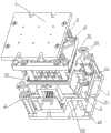
图1是本发明结构示意图。 Fig. 1 is a schematic diagram of the structure of the present invention.
图2是本发明立体图。 Fig. 2 is a perspective view of the present invention.
图3是本发明轴测图。 Fig. 3 is a perspective view of the present invention.
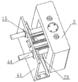
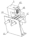
图4是支撑块结构示意图。 Fig. 4 is a schematic diagram of the structure of the support block.
图5是支撑块轴测图。 Figure 5 is an axonometric view of the support block.
图6是支撑块剖开图。 Fig. 6 is a sectional view of the support block.
图7是蒸制仓结构示意图。 Fig. 7 is a schematic diagram of the structure of the steaming chamber.
图8是蒸制仓与连接板装配示意图。 Fig. 8 is a schematic diagram of the assembly of the steaming bin and the connecting plate.
图9是料盘组件结构示意图。 Fig. 9 is a schematic diagram of the structure of the tray assembly.
图10是料盘组件俯视图。 Figure 10 is a top view of the tray assembly.
图11是料盘结构示意图。 Fig. 11 is a schematic diagram of the structure of the tray.
图12是母板结构示意图。 Figure 12 is a schematic diagram of the motherboard structure.
图13是基板结构示意图。 Fig. 13 is a schematic diagram of the substrate structure.
图14是卡槽结构示意图。 Fig. 14 is a schematic diagram of the structure of the card slot.
图15是料盘组件装配示意图。 Figure 15 is a schematic diagram of assembly of the tray assembly.
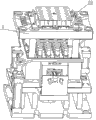
图16是本发明与油压机装配示意图。 Fig. 16 is a schematic diagram of the assembly of the present invention with a hydraulic press.
图中,上承板1,下承板2,支撑块3,模腔板4,导柱5,导套一6,上柱头7,活动板8,蒸制仓9,下柱头10,顶柱11,气缸一12、气缸二13,下模支柱14,气缸三15,硅胶垫16,卡槽本体17,定位孔18,立板19,底板一20,底板二21,连接块22,浮动接头23,锁模孔24,定位板25,蒸汽出口26,导套二27,基板28,料盘29,提手30,拉把31,定位销32,母板33,卡块34,卡槽35,料仓36,通孔37,锁模器38,连接板39,模孔40,小支架41,弹簧42,导杆一43,导向柱44,小弹簧45,导杆二46,台板47,油压机48,主油缸49,副油缸50,活动梁51,下梁52,导向套53。
In the figure, the
具体实施方式 Detailed ways
以下结合附图说明和具体实施方式对本发明作进一步的详细描述。 The present invention will be further described in detail below in conjunction with the accompanying drawings and specific embodiments.
参见图1-图6,一种小饼茶压制成型模具,其与油压机48配合使用,本油压机48采用PLC可编程控制系统实现自动化控制,油压机48操作面板上设有下压、上移、装料、装料完成、制作茶饼等按钮,各按钮分别通过信号线与PLC 可编程控制系统相连接;油压机48的上限位、快进起始位、工进起始位、工进停止位、下限位各处的检测开关分别通过信号线与PLC 可编程控制系统相连接;油压机48的副油缸50设置有内置磁环,副油缸50缸体上安装有位置检测开关,本位置检测开关通过信号线与PLC 可编程控制系统相连接;气缸一12、气缸二13和气缸三15的位置检测传感器分别通过信号线与PLC 可编程控制系统相连接,从而实现压茶过程的自动化控制。本小饼茶压制成型模具包括上模和下模,所述的上模包括上承板1、定位板25、导柱5和若干均匀布置的上柱头7。上承板1两端设置有锁模孔14,上承板1通过锁模器38固定在油压机48的活动梁51上;所述的上承板1和定位板25通过螺栓固定连接,所述的上柱头7贯穿定位板25并通过螺栓固定在定位板25上,所述的导柱5上端分别固定在上承板1的四角。所述的下模包括机架、模腔板4、连接板39、活动板8、顶柱11、下模支柱14、两个气缸一12、两个气缸二13、两个气缸三15、两个连接块22、两个小支架41、两个台板47和两个支撑块3。所述的机架包括底板一20、底板二21、立板19和下承板2,下承板2上设置有锁模孔14,下承板2通过锁模器38固定在油压机48的下梁52上;所述的立板19下端固定在下承板2上,立板19上端固定在底板二21底面,所述的底板二21和底板一20固定连接。所述的模腔板4上对应上柱头7设置有模孔40,模腔板4四角对应导柱5设置有与导柱5配合的导套一6;所述的连接板39内部中空、设置在活动板8的上方,连接板39通过导杆一43、弹簧42与活动板8活动连接,所述的活动板8上对应模孔40设置有下柱头10;优选的,连接板39上平面设置有凹槽,所述的凹槽内设置有硅胶垫16。因为需要压制成型的茶砖往往是带有图案、字体、商标等信息,优选的,上柱头7和下柱头10表面设置有雕刻图案,图案为汉字、数字或者其他图案或者符号,这样压制完成以后,茶砖就被塑造成带有各种信息,提升了产品的商品价值。所述的下模支柱14上端固定在模腔板4上,下模支柱14贯穿活动板8下端固定在底板一20上;优选的活动板8和下模支柱14 之间设置有导套二27,导套二27固定在活动板8上,导套二27可沿下模支柱14上下滑动。所述顶柱11穿过底板一20和底板二21中心的让位孔,其上端固定在活动板8底面中心位置,且顶柱11在让位孔中上下自由移动,所述下承板2对应顶柱11位置开设有孔径大于顶柱11外径的中心孔;实际使用中立板19及顶柱11长度依据模腔板4对地面相对高度来定,高度设置在800-950mm为宜,这样方便操作。所述两个气缸一12的后端分别固定在下承板2斜对角上,两个气缸一12的前端分别通过支撑固定在底板二21上,两个气缸一12前端的活塞杆头通过浮动接头23分别连接在连接板39斜对角的凸沿上;气缸的前端指的是气缸缸体前端,气缸的后端指的是气缸缸体后端,活塞杆穿过气缸前端的中心孔。所述两个气缸二13的后端分别固定在连接板39相对边的中部凸块上,两个气缸二13前端的活塞杆头分别通过浮动接头23连接在连接块22下端,所述的连接块22上端固定在活动板8的底面上。所述两个气缸三15的后端分别固定在小支架41的顶端,两个气缸三15前端的活塞杆头分别与台板47相固定,所述的小支架41底部固定在底板二21上,两个气缸三15分别贯穿两个支撑块3的中部孔,所述的支撑块3通过小弹簧45与台板47相连接;优选的,两个气缸三15的两侧对应设置有导向柱44,所述导向柱44的一端与台板47相固定,导向柱44的另一端穿过小支架41,导向柱44和小支架41之间设置有导向套53,导向柱44起导向作用,并且能够承担一定的非轴向负载;优选的,所述的小弹簧45两侧对应设置有导杆二46,所述导杆二46的下端固定在台板47上,导杆二46的上端贯穿支撑块3并与支撑块3滑动连接,这样支撑块3可以沿着导杆二46上下移动。在茶坯压制过程中,支撑块3将油压机48的主油缸49施加给活动板8的压力传递给底板一20,由底板一20通过底板二21、立板19、下承板2传递给油压机48的下梁52。
Referring to Fig. 1-Fig. 6, a kind of small cake tea pressing molding mold, it is used in conjunction with
参见图7-图8,所述的下模还包括有蒸制仓9,所述的蒸制仓9为中空框体,蒸制仓9与连接板39相固定,所述的活动板8板体置于蒸制仓9框体内,蒸制仓9一侧壁上设置有蒸汽出口26。工作时,本小饼茶压制成型模具可以外连蒸制设备和排气管道,蒸制设备的蒸汽通过模孔40进入蒸制仓9,流经蒸制仓9的蒸汽通过蒸汽出口26排入排气管道,最后将将蒸汽排出压制车间,从而保证了茶坯的压制环境。
Referring to Figures 7-8, the lower mold also includes a
参见图9-图15,所述的模腔板4设置有与其配合使用的料盘组件,所述的料盘组件包括基板28、料盘29和母板33。所述的料盘29上对应模孔40设置有料仓36,所述的母板33上对应料仓36设置有通孔37,所述的基板28上开设有与通孔37相对应的圆孔,所述料盘29设置在母板33的顶面上且料仓36底端置于通孔37内;所述基板28设置在母板33的底面上,且基板28与母板33之间通过卡槽35滑动连接,基板28的两端分别设置有拉把31,母板33的两端设置有提手30,所述的提手30外侧两端设置有定位销32,所述模腔板4上对应定位销32设置有定位孔18。所述的卡槽35包括卡块34和卡槽本体17,所述的卡块34固定在卡槽本体17的上端,卡块34与卡槽本体17下端的凸边之间形成槽口;基板28和母板33的边卡进槽口内,且卡块34与母板33通过螺钉固定连接,基板28则可以沿着槽口滑动。
Referring to FIGS. 9-15 , the cavity plate 4 is provided with a tray assembly used in conjunction with it, and the tray assembly includes a
参见图1-图16,工作时,首先开启油压机48,使油压机48的活动梁51处于快进起始位;将本茶叶压制成型模具之上模和下模组件移入油压机48的下梁52与活动梁51之间并置于下梁52上,将下承板2与下梁52通过锁模器38进行固定。按动油压机48控制面板上的下压按钮使油压机48的活动梁51下移至接近上承板1,通过锁模器38将上承板1与活动梁51固定;按动油压机48控制面板上的上移按钮使活动梁51上移至快进起始位,此时上柱头7距离模腔板4上表面约350mm,两个气缸一12的活塞杆处于缩回状态,两个气缸二13的活塞杆处于自由伸缩状态,两个气缸三15的活塞杆处于缩回状态;此处的活塞杆处于自由伸缩状态即是指就是气缸没有通气,活塞杆左右可以移动的状态。将料盘组件中基板28的拉把31拉向左侧,此时基板28上的圆孔与母板33上的通孔37相错开,再将蒸制好的茶坯原料放入料盘29的料仓36中,此时茶坯原料不会从基板28上的圆孔中落出。按动油压机48控制面板上的“装料”按钮,PLC 可编程控制系统发出信号控制,两个气缸一12的活塞杆伸出,两个气缸二13的活塞杆缩回,此时下柱头10几乎与模腔板4上表面平齐;然后提起提手30使料盘组件水平移至模腔板4上方,将定位销32置于相对应的定位孔18中,从而将料盘组件置于模腔板4上端面上,此时料仓36与模腔板4的模孔40正对应,拉动右边拉把31,基板28上的圆孔与母板33上的通孔37正对应,按动油压机48控制面板上的“装料完成”按钮,气缸二13活塞杆伸出,此时下柱头10下移出模孔40,并与模腔板4下表面距离约为0.5-3mm,茶坯落入模腔板4的模孔40中,完成装茶,移出料盘组件。接下来,PLC 可编程控制系统发出信号控制,两个气缸二13的活塞杆处于自由伸缩状态,油压机48的副油缸50活塞杆伸出,下柱头10移入模孔40中6-10mm,气缸三15活塞杆伸出,支撑块3置于活动板8与底板一20之间,两个气缸一12的活塞杆处于自由伸缩状态,副油缸48活塞杆缩回,活动板8压触在支撑块3的上表面,下柱头10下移2mm,油压机48的主油缸49活塞杆快速下行,待油压机48的活动梁51下行至工进起始位,主油缸49活塞杆缓慢下行,上柱头7压入模孔40,待活动梁51下行至工进停止位,主油缸49活塞杆停止移动,此时上柱头7距离下柱头10上表面约5mm。接下来,PLC 可编程控制系统启动计时器,保压m秒,m根据设计确定其值,一般情况下10s<m<600s。最后,PLC 可编程控制系统发出信号,油压机48的主油缸49活塞杆快速缩回,油压机48的活动梁51上行至快进起始位,主油缸49活塞杆停止,上柱头7随活动梁51上移出模孔40,油压机48的副油缸50活塞杆顶出,下柱头10上移2mm,气缸三15活塞杆缩回,副油缸50活塞杆缩回,下柱头10移出模孔40,气缸一12活塞杆缩回,主油缸49活塞杆下行,活动梁51下行至下限位,上柱头7压入模孔40至与模腔板4下表面平齐,主油缸49活塞杆快速缩回,上柱头7随活动动梁51上移出模孔40,活动梁51上行至快进起始位,主油缸49活塞杆停止,压制完成的茶饼自动落下,拾起,完成一个生产周期。
Referring to Fig. 1-Fig. 16, when working, first open the
参见图1-图16,工作时,本小饼茶压制成型模具可以外连蒸制设备和排气管道,此时需先将称量好的茶坯原料通过料盘组件装入模孔40中,然后启动外连的蒸制设备进行蒸制,整治过程中的蒸汽通过蒸汽出口26排入排气管道,最后将蒸汽排出压制车间,接下来进行压制,经过一定时间保压、压制好的茶饼坯自动落下,拾起,完成一个生产周期。
Referring to Fig. 1-Fig. 16, during operation, the small cake tea pressing mold can be externally connected with steaming equipment and exhaust pipes. At this time, the weighed tea base raw materials need to be loaded into the
以上内容是结合具体的优选实施方式对本发明所作的进一步详细说明,不能认定本发明的具体实施只局限于这些说明。对于本发明所属技术领域的普通技术人员来说,在不脱离本发明构思的前提下,还可以做出若干简单推演或替换,上述结构都应当视为属于本发明的保护范围。 The above content is a further detailed description of the present invention in conjunction with specific preferred embodiments, and it cannot be assumed that the specific implementation of the present invention is limited to these descriptions. For those of ordinary skill in the technical field to which the present invention belongs, some simple deduction or replacement can also be made without departing from the concept of the present invention, and the above structures should be regarded as belonging to the protection scope of the present invention.
Claims (10)
Priority Applications (1)
| Application Number | Priority Date | Filing Date | Title |
|---|---|---|---|
| CN201310304898.7A CN103380831B (en) | 2013-07-19 | 2013-07-19 | Small cake tea press forming mold |
Applications Claiming Priority (1)
| Application Number | Priority Date | Filing Date | Title |
|---|---|---|---|
| CN201310304898.7A CN103380831B (en) | 2013-07-19 | 2013-07-19 | Small cake tea press forming mold |
Publications (2)
| Publication Number | Publication Date |
|---|---|
| CN103380831A true CN103380831A (en) | 2013-11-06 |
| CN103380831B CN103380831B (en) | 2014-08-06 |
Family
ID=49488921
Family Applications (1)
| Application Number | Title | Priority Date | Filing Date |
|---|---|---|---|
| CN201310304898.7A Active CN103380831B (en) | 2013-07-19 | 2013-07-19 | Small cake tea press forming mold |
Country Status (1)
| Country | Link |
|---|---|
| CN (1) | CN103380831B (en) |
Cited By (13)
| Publication number | Priority date | Publication date | Assignee | Title |
|---|---|---|---|---|
| CN104757157A (en) * | 2015-04-24 | 2015-07-08 | 福建省天丰源茶产业有限公司 | A device and control method for pressing tea cake |
| CN104886739A (en) * | 2015-06-25 | 2015-09-09 | 瓮安县任九妹食品有限责任公司 | Yellow glutinous rice cake making and forming device |
| CN105010603A (en) * | 2015-07-31 | 2015-11-04 | 湖北省农业科学院果树茶叶研究所 | Compression forming device and technology for craft brick tea |
| CN105235256A (en) * | 2015-08-25 | 2016-01-13 | 福建达盛香业有限公司 | Automatic production equipment for tapered grain incense |
| CN105594895A (en) * | 2016-02-23 | 2016-05-25 | 周显波 | Pressing die and pressing method of tea |
| CN106720558A (en) * | 2016-12-30 | 2017-05-31 | 湖北省农业科学院果树茶叶研究所 | Moulding process is steamed in a kind of tea base steamer and mould |
| CN106804775A (en) * | 2017-02-13 | 2017-06-09 | 湖北省农业科学院果树茶叶研究所 | A double-station brick tea pressing mold |
| CN107042650A (en) * | 2016-12-30 | 2017-08-15 | 湖北省农业科学院果树茶叶研究所 | A kind of tealeaves pressure setting and compressing technique |
| CN107047821A (en) * | 2017-02-13 | 2017-08-18 | 湖北省农业科学院果树茶叶研究所 | A kind of multistation brick tea compacting tool set |
| CN109329468A (en) * | 2018-11-28 | 2019-02-15 | 霍山汉唐清茗茶叶有限公司 | A kind of tea cake maker |
| CN109331194A (en) * | 2018-11-19 | 2019-02-15 | 湖北科技学院 | A mold disinfection device on tea brick marking equipment |
| CN110771700A (en) * | 2019-10-31 | 2020-02-11 | 湖南安化芙蓉山茶业有限责任公司 | Pressing machine for coin-shaped thin tea slices |
| CN114868946A (en) * | 2022-04-13 | 2022-08-09 | 东台市汉源食品机械制造有限公司 | Separating material returning type block food forming die |
Citations (5)
| Publication number | Priority date | Publication date | Assignee | Title |
|---|---|---|---|---|
| CN201008326Y (en) * | 2007-02-09 | 2008-01-23 | 赵健 | Processing equipment of minisize tea cake |
| DE102010001425A1 (en) * | 2010-02-01 | 2011-08-04 | Martin Bauer GmbH & Co. KG, 91487 | Extrusion of extracts, flavors and/or vitamins to produce storage-stable granules, which are useful as food ingredients for tea and tea-like products, where long-chain inulin is used as formulation component |
| CN102356783A (en) * | 2011-09-29 | 2012-02-22 | 广西梧州茂圣茶业有限公司 | Semi-automatic tea wafer machine and tea wafering process |
| CN103141535A (en) * | 2013-01-10 | 2013-06-12 | 铜陵市松马食品包装机械制造有限责任公司 | Multifunctional cake forming machine |
| CN203378506U (en) * | 2013-07-19 | 2014-01-08 | 湖北省农业科学院果树茶叶研究所 | Small cake tea pressing and forming mould |
-
2013
- 2013-07-19 CN CN201310304898.7A patent/CN103380831B/en active Active
Patent Citations (5)
| Publication number | Priority date | Publication date | Assignee | Title |
|---|---|---|---|---|
| CN201008326Y (en) * | 2007-02-09 | 2008-01-23 | 赵健 | Processing equipment of minisize tea cake |
| DE102010001425A1 (en) * | 2010-02-01 | 2011-08-04 | Martin Bauer GmbH & Co. KG, 91487 | Extrusion of extracts, flavors and/or vitamins to produce storage-stable granules, which are useful as food ingredients for tea and tea-like products, where long-chain inulin is used as formulation component |
| CN102356783A (en) * | 2011-09-29 | 2012-02-22 | 广西梧州茂圣茶业有限公司 | Semi-automatic tea wafer machine and tea wafering process |
| CN103141535A (en) * | 2013-01-10 | 2013-06-12 | 铜陵市松马食品包装机械制造有限责任公司 | Multifunctional cake forming machine |
| CN203378506U (en) * | 2013-07-19 | 2014-01-08 | 湖北省农业科学院果树茶叶研究所 | Small cake tea pressing and forming mould |
Non-Patent Citations (1)
| Title |
|---|
| 汤兴初,等: "含水量和加工压力对紧压茶成型及品质的影响", 《茶叶通讯》 * |
Cited By (23)
| Publication number | Priority date | Publication date | Assignee | Title |
|---|---|---|---|---|
| CN104757157A (en) * | 2015-04-24 | 2015-07-08 | 福建省天丰源茶产业有限公司 | A device and control method for pressing tea cake |
| CN104886739B (en) * | 2015-06-25 | 2016-09-21 | 瓮安县任九妹食品有限责任公司 | Yellow cake makes shaped device |
| CN104886739A (en) * | 2015-06-25 | 2015-09-09 | 瓮安县任九妹食品有限责任公司 | Yellow glutinous rice cake making and forming device |
| CN105010603A (en) * | 2015-07-31 | 2015-11-04 | 湖北省农业科学院果树茶叶研究所 | Compression forming device and technology for craft brick tea |
| CN105010603B (en) * | 2015-07-31 | 2018-09-28 | 湖北省农业科学院果树茶叶研究所 | A kind of technique brick tea compression molding device and tealeaves compression moulding technique |
| CN105235256B (en) * | 2015-08-25 | 2018-06-08 | 福建达盛香业有限公司 | Bore grain perfume (or spice) automatic producing device |
| CN105235256A (en) * | 2015-08-25 | 2016-01-13 | 福建达盛香业有限公司 | Automatic production equipment for tapered grain incense |
| CN105594895A (en) * | 2016-02-23 | 2016-05-25 | 周显波 | Pressing die and pressing method of tea |
| CN107042650B (en) * | 2016-12-30 | 2019-09-17 | 湖北省农业科学院果树茶叶研究所 | A kind of tealeaves pressure setting and compression moulding technique |
| CN107042650A (en) * | 2016-12-30 | 2017-08-15 | 湖北省农业科学院果树茶叶研究所 | A kind of tealeaves pressure setting and compressing technique |
| CN106720558A (en) * | 2016-12-30 | 2017-05-31 | 湖北省农业科学院果树茶叶研究所 | Moulding process is steamed in a kind of tea base steamer and mould |
| CN106720558B (en) * | 2016-12-30 | 2024-03-01 | 湖北省农业科学院果树茶叶研究所 | A tea base steaming device and in-mold steaming and molding process |
| CN107047821B (en) * | 2017-02-13 | 2023-08-22 | 湖北省农业科学院果树茶叶研究所 | Multi-station brick tea pressing die |
| CN106804775A (en) * | 2017-02-13 | 2017-06-09 | 湖北省农业科学院果树茶叶研究所 | A double-station brick tea pressing mold |
| CN107047821A (en) * | 2017-02-13 | 2017-08-18 | 湖北省农业科学院果树茶叶研究所 | A kind of multistation brick tea compacting tool set |
| CN106804775B (en) * | 2017-02-13 | 2023-09-26 | 湖北省农业科学院果树茶叶研究所 | A double-station brick tea pressing mold |
| CN109331194A (en) * | 2018-11-19 | 2019-02-15 | 湖北科技学院 | A mold disinfection device on tea brick marking equipment |
| CN109331194B (en) * | 2018-11-19 | 2023-12-22 | 湖北科技学院 | A mold disinfection device on tea brick marking equipment |
| CN109329468A (en) * | 2018-11-28 | 2019-02-15 | 霍山汉唐清茗茶叶有限公司 | A kind of tea cake maker |
| CN110771700A (en) * | 2019-10-31 | 2020-02-11 | 湖南安化芙蓉山茶业有限责任公司 | Pressing machine for coin-shaped thin tea slices |
| CN110771700B (en) * | 2019-10-31 | 2024-04-02 | 湖南安化芙蓉山茶业有限责任公司 | Coin-shaped flake tea pressing machine |
| CN114868946B (en) * | 2022-04-13 | 2023-01-03 | 东台市汉源食品机械制造有限公司 | Separating material returning type block food forming die |
| CN114868946A (en) * | 2022-04-13 | 2022-08-09 | 东台市汉源食品机械制造有限公司 | Separating material returning type block food forming die |
Also Published As
| Publication number | Publication date |
|---|---|
| CN103380831B (en) | 2014-08-06 |
Similar Documents
| Publication | Publication Date | Title |
|---|---|---|
| CN103380831B (en) | Small cake tea press forming mold | |
| CN103381666A (en) | Automatic press forming equipment for small tea cake and press forming technological process thereof | |
| CN103392843B (en) | Tea leaf pressing-forming equipment and tea leaf pressing-forming technical process | |
| CN105010603B (en) | A kind of technique brick tea compression molding device and tealeaves compression moulding technique | |
| CN102356783B (en) | Semi-automatic tea cake press and tea cake pressing process | |
| CN203381219U (en) | Automatic pressing formation device for small cake tea | |
| CN203378506U (en) | Small cake tea pressing and forming mould | |
| CN107042650A (en) | A kind of tealeaves pressure setting and compressing technique | |
| CN104757157A (en) | A device and control method for pressing tea cake | |
| CN103170925A (en) | Automatic grinding wheel stripping machine | |
| CN103950138A (en) | Semi-automatic brake block compressing machine | |
| CN210412186U (en) | Mould for forming mechanical parts | |
| CN204907762U (en) | Technology brick tea press forming equipment | |
| CN208118034U (en) | A kind of plank molding hot press | |
| CN206498851U (en) | A kind of tealeaves pressure setting | |
| CN202623082U (en) | Automatic demoulding mould for producing degradable tableware | |
| CN213002431U (en) | High temperature resistance flange forging mould | |
| CN203378507U (en) | Tea press forming equipment | |
| CN106720558A (en) | Moulding process is steamed in a kind of tea base steamer and mould | |
| CN208469128U (en) | Brake block hot press | |
| CN204599198U (en) | A kind of device of pressed tea cake | |
| CN216941533U (en) | Quick demoulding device is used in production of rubber sole | |
| CN211031041U (en) | Insulating inserted sheet injection mold | |
| CN218489383U (en) | Thin-wall metal plate movable core embossing die and embossing machine | |
| CN214645601U (en) | Multi-stage ejection mechanism of silicone products extruder |
Legal Events
| Date | Code | Title | Description |
|---|---|---|---|
| C06 | Publication | ||
| PB01 | Publication | ||
| C10 | Entry into substantive examination | ||
| SE01 | Entry into force of request for substantive examination | ||
| C14 | Grant of patent or utility model | ||
| GR01 | Patent grant | ||
| EE01 | Entry into force of recordation of patent licensing contract | ||
| EE01 | Entry into force of recordation of patent licensing contract |
Application publication date: 20131106 Assignee: Chibi Zhaoliqiao tafeng Tea Industry Co.,Ltd. Assignor: INSTITUTE OF FRUIT AND TEA, HUBEI ACADEMY OF AGRICULTURAL SCIENCES Contract record no.: X2022980013045 Denomination of invention: A kind of small cake tea pressing mould Granted publication date: 20140806 License type: Common License Record date: 20220826 |