CN103350375A - Water pump shaft end face grinding device - Google Patents
Water pump shaft end face grinding device Download PDFInfo
- Publication number
- CN103350375A CN103350375A CN2013103084786A CN201310308478A CN103350375A CN 103350375 A CN103350375 A CN 103350375A CN 2013103084786 A CN2013103084786 A CN 2013103084786A CN 201310308478 A CN201310308478 A CN 201310308478A CN 103350375 A CN103350375 A CN 103350375A
- Authority
- CN
- China
- Prior art keywords
- fixed
- screw
- screws
- planker
- workbench
- Prior art date
- Legal status (The legal status is an assumption and is not a legal conclusion. Google has not performed a legal analysis and makes no representation as to the accuracy of the status listed.)
- Pending
Links
- XLYOFNOQVPJJNP-UHFFFAOYSA-N water Substances O XLYOFNOQVPJJNP-UHFFFAOYSA-N 0.000 title abstract 2
- 229910001651 emery Inorganic materials 0.000 claims description 11
- 229910003460 diamond Inorganic materials 0.000 claims description 5
- 239000010432 diamond Substances 0.000 claims description 5
- 230000003139 buffering effect Effects 0.000 abstract 1
- 239000003921 oil Substances 0.000 description 13
- 230000005611 electricity Effects 0.000 description 3
- 230000033001 locomotion Effects 0.000 description 2
- 230000006835 compression Effects 0.000 description 1
- 238000007906 compression Methods 0.000 description 1
- 230000000694 effects Effects 0.000 description 1
- 230000005484 gravity Effects 0.000 description 1
- 239000010720 hydraulic oil Substances 0.000 description 1
- 230000001681 protective effect Effects 0.000 description 1
- 238000009966 trimming Methods 0.000 description 1
Images



Landscapes
- Grinding Of Cylindrical And Plane Surfaces (AREA)
Abstract
The invention discloses a water pump shaft end face grinding device. A grinding support oil cylinder is fixed with a grinding support through screws. A grinding support piston rod in the grinding support oil cylinder is fixed with a support through a nut and fixed with a grinding dragging plate by the main shaft shell body through screws. An electric main shaft shell body is clamped with an electric main shaft inside through screws. A grinding wheel is fixed on the electric main shaft through nuts. A guiding shaft is placed in a bearing block. A buffering oil cylinder is fixed with a bed body through screws. An operation platform upper dragging plate is fixed on an operation platform lower dragging plate through a guide rail. An operation platform oil cylinder is fixed on the operation platform upper dragging plate through screws. An operation platform support is fixed on the operation platform lower dragging plate through screws. A locating piece is embedded on the operation platform upper dragging plate in an interference fit mode through screws. A motor belt wheel is fixed on a motor. A cantilever is clamped on a bottom board of the motor through screws. A workpiece shaft is fixed on the cantilever through screws. One end of the workpiece shaft is fixed with a workpiece shaft belt wheel through screws. The other end of the workpiece shaft is fixed with a pressing wheel through screws.
Description
Technical field:
The present invention relates to a kind of grinding attachment, be specially adapted to the grinding of pump shaft end face.
Background technology:
Existing pump shaft cross grinding mostly is to rely on manually to compress, the feeding grinding of emery wheel, and its shortcoming is: this manual compression mode is unreliable, dangerous, labour intensity large, poor stability, can not effectively control grinding quality and size.
Summary of the invention:
Task of the present invention is that a kind of cost of proposition is low, and is safe, reliable, and can effectively control a kind of pump shaft face grinding device of grinding quality and size.
Task of the present invention is finished like this, a kind of pump shaft face grinding device, it is characterized in that: grinding machine frame planker is fixed by guide rail and lathe bed, mill frame oil cylinder is fixed by screw and mill frame, mill frame piston rod in the described mill frame oil cylinder is fixed by nut and bearing, adding planker by the main shaft housing by screw and mill fixes, by screws clamp electric main shaft is arranged in the described electric main shaft housing, be fixed with emery wheel by nut on the described electric main shaft, wheel guard is fixed by screw and the axis of guide, the built-in axis of guide that is placed with of bearing block, cushion cylinder is fixed by screw and lathe bed, damper piston is housed in the cushion cylinder, be fixed with planker on the workbench by guide rail on the planker under the workbench, planker is fixed with the workbench oil cylinder by screw on the workbench, be fixed with table rest by screw on the planker under the workbench, be fixed with dog screw by nut on the positioning seat, locating piece is embedded on the workbench on the planker by the screw interference fit, rotating seat is fixed by planker on screw and the workbench, be fixed with motor pulley on the motor, cantilever is stuck on the electric baseboard by screw, be fixed with workpiece spindle by screw on the cantilever, one end of workpiece spindle is fixed with the workpiece spindle belt pulley by screw, the other end of workpiece spindle is fixed with pinch roller by screw, block bearing and supporting base are fixed, be placed with workpiece on the described block bearing, sliding seat is fixed by screws on the backing plate, and putting in the sliding seat has sliding axle, be fixed with the pushing handle by bearing pin on the sliding axle, diamond pen is fixed by screw.Described bearing block is fixed by screw and mill frame planker, by screws clamp mill frame dog screw is arranged on the described fixed block, and described positioning seat is fixed on the lathe bed, and described backing plate is fixed by screw and lathe bed.
The present invention has following effect: the technical program is leaned on hydraulic oil cylinder driving, gravity-pressing, and simple in structure, cost is low, and is safe and reliable, and good stability can effectively be controlled grinding quality and size.
Description of drawings:
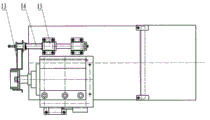
Fig. 1 is the structural representation of this programme; Fig. 2 is that Fig. 1 K is to cutaway view; Fig. 3 is the top view of Fig. 2; Fig. 4 is that Fig. 1 P is to the structural representation of 90-degree rotation; Fig. 5 is the top view of Fig. 4.
Drawing explanation: 1, lathe bed, 2, emery wheel, 3, the electricity main shaft, 4, electricity main shaft housing, 5, mill frame planker, 6, bearing, 7, mill frame piston rod, 8, mill frame oil cylinder, 9, fixed block, 10, mill frame dog screw, 11, damper piston, 12, cushion cylinder, 13, wheel guard, 14, the axis of guide, 15, bearing block, 16, push and pull bar, 17, sliding axle, 18, sliding seat, 19, cantilever, 20, adjustment screw, 21, motor, 22, electric baseboard, 23, rotating seat, 24, planker on the workbench, 25, the workbench oil cylinder, 26, the workbench piston rod, 27, table rest, 28, planker under the workbench, 29, locating piece, 30, dog screw, 31, positioning seat, 32, backing plate, 33, supporting base, 34, workpiece, 35, block bearing, 36, support, 37, the workpiece spindle belt pulley, 38, workpiece spindle, 39, motor pulley, 40, pinch roller, 41, diamond pen.
The specific embodiment:
Describe embodiment in detail in conjunction with above accompanying drawing, referring to Fig. 2 and shown in Figure 3, mill frame planker 5 is fixing by guide rail and lathe bed 1, but move left and right, mill frame oil cylinder 8 is fixed by screw and mill frame, the mill frame is fixed on the lathe bed, mill frame piston rod 7 in the described mill frame oil cylinder is fixing by nut and bearing 6, bearing is fixed by screws on the lathe bed, fixing with mill frame planker 5 by screw by main shaft housing 4, by screws clamp electric main shaft 3 is arranged in the described electric main shaft housing, be fixed with emery wheel 2 by nut on the described electric main shaft, wheel guard is fixing by screw and the axis of guide 14, the bearing block 15 built-in axis of guides that are placed with, can horizontally slip, described bearing block is fixed by screw and mill frame planker, and fixed block 9 is fixed by screw and mill frame planker, by screws clamp mill frame dog screw 10 is arranged on the fixed block, cushion cylinder 12 is fixing by screw and lathe bed 1, has damper piston 11 to be fixed under the workbench planker in the cushion cylinder and fixes by screw and lathe bed.
See Fig. 4 and shown in Figure 5, be fixed with planker 24 on the workbench by guide rail on the planker 28 under the workbench, can move forward and backward, planker is fixed with workbench oil cylinder 25 by screw on the workbench, be fixed with table rest 27 by screw on the planker under the workbench, workbench piston rod 26 is fixed on the table rest by nut, be fixed with dog screw 30 by nut on the positioning seat 31, positioning seat is fixed on the lathe bed 1, locating piece 29 is embedded on the workbench on the planker by the screw interference fit, rotating seat 23 is fixed by planker on screw and the workbench, when unclamping hold-down screw, can rotate to an angle around pivot, be fixed with electric baseboard 22 on the rotating seat, be fixed with motor 21 and adjustment screw 20 on the electric baseboard 22, be fixed with motor pulley 39 on the motor 21, cantilever 19 is stuck on the electric baseboard 22 by screw, can be around screw turns, be fixed with workpiece spindle 38 by screw on the cantilever, one end of workpiece spindle is fixed with workpiece spindle belt pulley 37 by screw, the other end of workpiece spindle is fixed with pinch roller 40 by screw, block bearing 35 is fixing with supporting base 33, be placed with workpiece 34 on the described block bearing, sliding seat 18 is fixed by screws on the backing plate 32, backing plate is fixing by screw and lathe bed 1, support 36 is fixed by screw and sliding seat, and putting in the sliding seat has sliding axle 17, is fixed with pushing handle 16 by bearing pin on the sliding axle, the pushing handle can rotate around bearing pin, and diamond pen 41 is fixed by screw.
Describe the implementation of this device in detail in conjunction with above embodiment, the electric main shaft 3 that electricity main shaft housing is 4 li drives emery wheel 2 High Rotation Speeds, 8 left side oil-feeds of mill frame oil cylinder, because mill frame piston rod 7 is fixed on the lathe bed 1 by bearing 6, mill frame oil cylinder 8 drives mill frame planker 5 left lateral, when the screw of fixed emery wheel cover 13 is run into the lathe bed left side, wheel guard 13 stops left lateral, the axis of guide 14 stops left lateral, bearing block 15 is followed mill frame planker 5 and is continued left lateral, make emery wheel 2 expose gradually protective hood of grinding wheel, when the mill frame dog screw 10 on the fixed block 9 is run into the damper piston 11 of 12 li of cushion cylinders, the damper piston left lateral is to the limit, and grind 5 stop motions of frame planker this moment, can regulate its position, left and right sides by rotating grinding frame dog screw 10.Workpiece 34 is positioned on the block bearing 35, and the quantity of block bearing 35 is 4, and the quantity of supporting base 33 is 2, can regulate the front and back position of front end supporting base 33 on backing plate 32 according to the length of workpiece.Adjust rotating seat 23, make pinch roller 40 and workpiece 34 form suitable angle beta, adjust adjustment screw 20, make the minimum point of pinch roller 40 lower than the peak of workpiece 34.During work, the motor 21 that is fixed on the electric baseboard 22 passes through motor pulley 39, workpiece spindle belt pulley 37 and polywedge bet, drive pinch roller 40 rotary table oil cylinders 25 left side oil-feeds on the workpiece spindle 38, because workbench piston rod 26 is fixed under the workbench on the planker 28 by table rest 27, workbench oil cylinder 26 drives planker 24 left lateral on the workbench, when the locating piece 29 on being embedded in workbench on the planker 24 is run into the dog screw 30 that is fixed on the positioning seat 31, pinch roller 40 is lifted by workpiece 34, cantilever 19 breaks away from adjustment screw 20, because the gravity of cantilever 19 and workpiece spindle 38 and pinch roller 40, pinch roller 40 drives workpiece 34 rotations by frictional force, because the existence of angle beta, in the time of workpiece 34 rotation, to close emery wheel direction motion, behind the contact emery wheel 2, namely begin grinding, after grinding finished, motor 21 counter-rotatings were when driving pinch roller 40 counter-rotating, workbench oil cylinder 25 drives pinch roller 40 right laterals, and pinch roller 40 breaks away from workpiece 34.When emery wheel need to be repaired, promote push and pull bar 16, because the restriction of support 36, sliding axle 17 drives diamond pen 41 move left and right trimming wheels.
Claims (2)
1. pump shaft face grinding device, it is characterized in that: grinding machine frame planker is fixed by guide rail and lathe bed, mill frame oil cylinder is fixed by screw and mill frame, mill frame piston rod in the described mill frame oil cylinder is fixed by nut and bearing, adding planker by the main shaft housing by screw and mill fixes, by screws clamp electric main shaft is arranged in the described electric main shaft housing, be fixed with emery wheel by nut on the described electric main shaft, wheel guard is fixed by screw and the axis of guide, the built-in axis of guide that is placed with of bearing block, cushion cylinder is fixed by screw and lathe bed, damper piston is housed in the cushion cylinder, be fixed with planker on the workbench by guide rail on the planker under the workbench, planker is fixed with the workbench oil cylinder by screw on the workbench, be fixed with table rest by screw on the planker under the workbench, be fixed with dog screw by nut on the positioning seat, locating piece is embedded on the workbench on the planker by the screw interference fit, rotating seat is fixed by planker on screw and the workbench, be fixed with motor pulley on the motor, cantilever is stuck on the electric baseboard by screw, be fixed with workpiece spindle by screw on the cantilever, one end of workpiece spindle is fixed with the workpiece spindle belt pulley by screw, the other end of workpiece spindle is fixed with pinch roller by screw, block bearing and supporting base are fixed, be placed with workpiece on the described block bearing, sliding seat is fixed by screws on the backing plate, putting in the sliding seat has sliding axle, is fixed with the pushing handle by bearing pin on the sliding axle, and diamond pen is fixed by screw.
2. a kind of pump shaft face grinding device according to claim 1, it is characterized in that: described bearing block is fixed by screw and mill frame planker, by screws clamp mill frame dog screw is arranged on the described fixed block, described positioning seat is fixed on the lathe bed, and described backing plate is fixed by screw and lathe bed.
Priority Applications (1)
| Application Number | Priority Date | Filing Date | Title |
|---|---|---|---|
| CN2013103084786A CN103350375A (en) | 2013-07-23 | 2013-07-23 | Water pump shaft end face grinding device |
Applications Claiming Priority (1)
| Application Number | Priority Date | Filing Date | Title |
|---|---|---|---|
| CN2013103084786A CN103350375A (en) | 2013-07-23 | 2013-07-23 | Water pump shaft end face grinding device |
Publications (1)
| Publication Number | Publication Date |
|---|---|
| CN103350375A true CN103350375A (en) | 2013-10-16 |
Family
ID=49306835
Family Applications (1)
| Application Number | Title | Priority Date | Filing Date |
|---|---|---|---|
| CN2013103084786A Pending CN103350375A (en) | 2013-07-23 | 2013-07-23 | Water pump shaft end face grinding device |
Country Status (1)
| Country | Link |
|---|---|
| CN (1) | CN103350375A (en) |
Cited By (3)
| Publication number | Priority date | Publication date | Assignee | Title |
|---|---|---|---|---|
| CN109382554A (en) * | 2018-10-10 | 2019-02-26 | 广州中汇达科技有限公司 | A kind of high-precision automobile crane thrust surface deburring machine |
| CN114750044A (en) * | 2022-05-11 | 2022-07-15 | 无锡市昌亿机床制造有限公司 | Measuring device for inner diameter measuring instrument of vertical grinding machine |
| CN118003230A (en) * | 2023-11-22 | 2024-05-10 | 威海金马笔业有限公司 | Penholder burnishing device is used in pencil production |
Citations (10)
| Publication number | Priority date | Publication date | Assignee | Title |
|---|---|---|---|---|
| JPH10263997A (en) * | 1997-03-27 | 1998-10-06 | Hitachi Zosen Corp | Polishing machine for end face of mold roll in continuous casting machine |
| CN2897539Y (en) * | 2006-03-06 | 2007-05-09 | 无锡开源机床集团有限公司 | Abrasive-wheel protector of internal grinder |
| CN201175852Y (en) * | 2008-04-09 | 2009-01-07 | 新乡日升数控轴承装备股份有限公司 | Numerical control bearing end plane grinding machine |
| CN201471226U (en) * | 2009-09-08 | 2010-05-19 | 新乡日升数控轴承装备股份有限公司 | Hydraulic oil cylinder of inner-diameter grinding machine |
| CN201693452U (en) * | 2010-06-11 | 2011-01-05 | 宁波更大集团有限公司 | Grinder working table positioning buffering device |
| CN201860366U (en) * | 2010-07-13 | 2011-06-08 | 上海未来宽带技术及应用工程研究中心有限公司 | Mobile telephone that can be used as a video source of a video live system |
| JP2011177827A (en) * | 2010-03-01 | 2011-09-15 | Toyo Advanced Technologies Co Ltd | Grinding device |
| CN202607472U (en) * | 2012-05-10 | 2012-12-19 | 长沙理工大学 | Polishing device for lathe |
| EP2570237A1 (en) * | 2010-05-11 | 2013-03-20 | Komatsu NTC Ltd. | Grinding machine |
| CN203390674U (en) * | 2013-07-23 | 2014-01-15 | 新乡日升数控轴承装备股份有限公司 | Grinding device for end surfaces of water pump shafts |
-
2013
- 2013-07-23 CN CN2013103084786A patent/CN103350375A/en active Pending
Patent Citations (10)
| Publication number | Priority date | Publication date | Assignee | Title |
|---|---|---|---|---|
| JPH10263997A (en) * | 1997-03-27 | 1998-10-06 | Hitachi Zosen Corp | Polishing machine for end face of mold roll in continuous casting machine |
| CN2897539Y (en) * | 2006-03-06 | 2007-05-09 | 无锡开源机床集团有限公司 | Abrasive-wheel protector of internal grinder |
| CN201175852Y (en) * | 2008-04-09 | 2009-01-07 | 新乡日升数控轴承装备股份有限公司 | Numerical control bearing end plane grinding machine |
| CN201471226U (en) * | 2009-09-08 | 2010-05-19 | 新乡日升数控轴承装备股份有限公司 | Hydraulic oil cylinder of inner-diameter grinding machine |
| JP2011177827A (en) * | 2010-03-01 | 2011-09-15 | Toyo Advanced Technologies Co Ltd | Grinding device |
| EP2570237A1 (en) * | 2010-05-11 | 2013-03-20 | Komatsu NTC Ltd. | Grinding machine |
| CN201693452U (en) * | 2010-06-11 | 2011-01-05 | 宁波更大集团有限公司 | Grinder working table positioning buffering device |
| CN201860366U (en) * | 2010-07-13 | 2011-06-08 | 上海未来宽带技术及应用工程研究中心有限公司 | Mobile telephone that can be used as a video source of a video live system |
| CN202607472U (en) * | 2012-05-10 | 2012-12-19 | 长沙理工大学 | Polishing device for lathe |
| CN203390674U (en) * | 2013-07-23 | 2014-01-15 | 新乡日升数控轴承装备股份有限公司 | Grinding device for end surfaces of water pump shafts |
Cited By (3)
| Publication number | Priority date | Publication date | Assignee | Title |
|---|---|---|---|---|
| CN109382554A (en) * | 2018-10-10 | 2019-02-26 | 广州中汇达科技有限公司 | A kind of high-precision automobile crane thrust surface deburring machine |
| CN114750044A (en) * | 2022-05-11 | 2022-07-15 | 无锡市昌亿机床制造有限公司 | Measuring device for inner diameter measuring instrument of vertical grinding machine |
| CN118003230A (en) * | 2023-11-22 | 2024-05-10 | 威海金马笔业有限公司 | Penholder burnishing device is used in pencil production |
Similar Documents
| Publication | Publication Date | Title |
|---|---|---|
| CN204843798U (en) | Duplex position horizontal axis round platform grinding machine | |
| CN102729107B (en) | Double-station high-precision rubber covered roller grinding machine | |
| CN204603983U (en) | A kind of knife sharpener grinding two-sided dise knife | |
| CN104325366A (en) | Electromechanical-control automatic tool sharpening machine | |
| CN203495704U (en) | Deburring device for steel plate | |
| CN216421944U (en) | Automatic feeding grinding and polishing machine | |
| CN216098172U (en) | Simple polishing and cutting integrated machine | |
| CN204171805U (en) | A kind of Electromechanical Control automatic knife grinder | |
| CN210588110U (en) | Brake disc grinding device | |
| CN203460005U (en) | Efficient multifunctional tool sharpener | |
| CN203390674U (en) | Grinding device for end surfaces of water pump shafts | |
| CN110524252A (en) | A kind of rubbing down truning fixture for cathode roll | |
| CN202726658U (en) | Double-station high-accuracy rubber roll grinding machine | |
| CN113352153A (en) | Knife sharpener convenient for multi-angle repeated polishing | |
| CN203901041U (en) | Grinding machine | |
| CN218169703U (en) | Quick moving device for central frame of numerical control roll grinder | |
| CN205497137U (en) | Cutter grinder bed | |
| CN217167791U (en) | Steel roller both ends processingequipment | |
| CN102091981B (en) | Crankshaft gate polishing device | |
| CN105057790A (en) | Full-automatic diamond saw blade double-faced sharpening machine | |
| CN205630165U (en) | Grind cup machine | |
| CN203636628U (en) | Lever-type grinding head lifting device | |
| CN108908061A (en) | Machine part polishing machine | |
| CN201872036U (en) | Crankshaft sprue polishing device | |
| CN203831248U (en) | Grinding wheel dressing device |
Legal Events
| Date | Code | Title | Description |
|---|---|---|---|
| C06 | Publication | ||
| PB01 | Publication | ||
| C10 | Entry into substantive examination | ||
| SE01 | Entry into force of request for substantive examination | ||
| C02 | Deemed withdrawal of patent application after publication (patent law 2001) | ||
| WD01 | Invention patent application deemed withdrawn after publication |
Application publication date: 20131016 |