CN103343800A - Speed reducer structure of lifting type platform lifting system - Google Patents
Speed reducer structure of lifting type platform lifting system Download PDFInfo
- Publication number
- CN103343800A CN103343800A CN2013102968953A CN201310296895A CN103343800A CN 103343800 A CN103343800 A CN 103343800A CN 2013102968953 A CN2013102968953 A CN 2013102968953A CN 201310296895 A CN201310296895 A CN 201310296895A CN 103343800 A CN103343800 A CN 103343800A
- Authority
- CN
- China
- Prior art keywords
- speed reducer
- gear
- gear reducer
- lifting
- planet
- Prior art date
- Legal status (The legal status is an assumption and is not a legal conclusion. Google has not performed a legal analysis and makes no representation as to the accuracy of the status listed.)
- Pending
Links
- 239000003638 chemical reducing agent Substances 0.000 title claims abstract description 50
- 230000003028 elevating effect Effects 0.000 claims description 11
- 238000004519 manufacturing process Methods 0.000 description 3
- 238000010586 diagram Methods 0.000 description 2
- 230000009286 beneficial effect Effects 0.000 description 1
- 238000005516 engineering process Methods 0.000 description 1
- 238000000034 method Methods 0.000 description 1
Images

Classifications
-
- E—FIXED CONSTRUCTIONS
- E02—HYDRAULIC ENGINEERING; FOUNDATIONS; SOIL SHIFTING
- E02B—HYDRAULIC ENGINEERING
- E02B17/00—Artificial islands mounted on piles or like supports, e.g. platforms on raisable legs or offshore constructions; Construction methods therefor
- E02B17/04—Equipment specially adapted for raising, lowering, or immobilising the working platform relative to the supporting construction
- E02B17/08—Equipment specially adapted for raising, lowering, or immobilising the working platform relative to the supporting construction for raising or lowering
- E02B17/0818—Equipment specially adapted for raising, lowering, or immobilising the working platform relative to the supporting construction for raising or lowering with racks actuated by pinions
Landscapes
- Engineering & Computer Science (AREA)
- General Engineering & Computer Science (AREA)
- Mechanical Engineering (AREA)
- Civil Engineering (AREA)
- Structural Engineering (AREA)
- Retarders (AREA)
Abstract
本发明公开了一种升降式平台升降系统的减速装置结构,包括桩箱及减速装置,所述减速装置包括斜齿轮减速机和行星齿轮减速机,所述斜齿轮减速机的输入轴连接电机,所述斜齿轮减速机的输出轴连接所述行星齿轮减速机,所述电机、所述斜齿轮减速机及所述行星齿轮减速机三者组成的整体呈U形设置在所述桩箱的侧面。这种减速装置结构合理、紧凑,重量轻,运转平稳,有效利用了桩箱空间,减轻平台了重量,能够实现升降系统的使用要求。
The invention discloses a deceleration device structure of a lifting platform lifting system, which includes a pile box and a deceleration device. The deceleration device includes a helical gear reducer and a planetary gear reducer. The input shaft of the helical gear reducer is connected to a motor. The output shaft of the helical gear reducer is connected to the planetary gear reducer, and the whole composed of the motor, the helical gear reducer and the planetary gear reducer is U-shaped and arranged on the side of the pile box . This kind of deceleration device has reasonable and compact structure, light weight, stable operation, effectively utilizes the pile box space, reduces the weight of the platform, and can meet the use requirements of the lifting system.
Description
技术领域 technical field
本发明涉及升降式平台的升降系统,具体的讲涉及一种升降式平台升降系统的减速装置结构。 The invention relates to a lifting system of a lifting platform, in particular to a structure of a deceleration device of the lifting system of a lifting platform.
背景技术 Background technique
升降式平台是一种用于海上能源开采和勘察的移动式海洋工程平台,其主要组成部分是工作平台,支撑平台的桩腿、控制工作平台升降的升降系统和工作平台定位后的锁紧系统。其中升降系统主要由电机、减速装置、抬升齿轮轴组件等组成。 The lifting platform is a mobile offshore engineering platform used for offshore energy exploitation and exploration. Its main components are the working platform, the legs supporting the platform, the lifting system that controls the lifting of the working platform and the locking system after the working platform is positioned. . The lifting system is mainly composed of motor, reduction device, lifting gear shaft assembly and so on.
升降系统的减速装置要求能够实现大减速比,输出大扭矩,其内部结构要有一定的承载能力,能满足强度要求。但其设计制造受到平台重量及空间等条件的限制,减速装置要求越小、越轻越好,而承重却非常大。一般来说,减速比需要5000左右,输出轴扭矩达1000000N/m以上。目前,国内缺乏这种重载大速比减速机构的设计制造经验,设计和制造难度大。如何合理有效的设计减速装置是一个非常重要的问题。 The deceleration device of the lifting system is required to achieve a large deceleration ratio and output a large torque, and its internal structure must have a certain bearing capacity to meet the strength requirements. However, its design and manufacture are limited by conditions such as platform weight and space. The smaller and lighter the reduction gear is, the better, but the load-bearing capacity is very large. Generally speaking, the reduction ratio needs to be about 5000, and the output shaft torque can reach more than 1000000N/m. At present, there is a lack of experience in the design and manufacture of such a heavy-duty large-speed ratio reduction mechanism in China, and the design and manufacture are difficult. How to design the reduction gear reasonably and effectively is a very important issue.
发明内容 Contents of the invention
本发明的目的在于:针对上述不足之处,提供一种结构合理紧凑、重量轻且运转平稳的升降式平台升降系统的减速装置结构。 The object of the present invention is to provide a structure of a deceleration device for an elevating platform elevating system with reasonable and compact structure, light weight and stable operation in view of the above disadvantages.
为了实现上述发明目的,本发明提供了以下技术方案: In order to realize the above-mentioned purpose of the invention, the present invention provides the following technical solutions:
一种升降式平台升降系统的减速装置结构,包括桩箱及减速装置,所述减速装置包括斜齿轮减速机和行星齿轮减速机,所述斜齿轮减速机的输入轴连接电机,所述斜齿轮减速机的输出轴连接所述行星齿轮减速机,所述电机、所述斜齿轮减速机及所述行星齿轮减速机三者组成的整体呈U形设置在所述桩箱的侧面。 A deceleration device structure for an elevating platform lifting system, including a pile box and a deceleration device, the deceleration device includes a helical gear reducer and a planetary gear reducer, the input shaft of the helical gear reducer is connected to a motor, and the helical gear The output shaft of the reducer is connected to the planetary gear reducer, and the whole composed of the motor, the helical gear reducer and the planetary gear reducer is U-shaped and arranged on the side of the pile box.
作为本发明的优选实施方式,所述斜齿轮减速机采用五平行轴四级减速结构经过四次减速增扭后通过输出轴连接所述行星齿轮减速机的输入轴。 As a preferred embodiment of the present invention, the helical gear reducer adopts a five-parallel-shaft four-stage reduction structure and is connected to the input shaft of the planetary gear reducer through the output shaft after four times of deceleration and torque increase.
作为本发明的优选实施方式,所述行星齿轮减速机采用两级减速结构并且每级减速都采用三个行星轮均布于太阳轮四周的结构。 As a preferred embodiment of the present invention, the planetary gear reducer adopts a two-stage reduction structure, and each stage of reduction adopts a structure in which three planetary gears are evenly distributed around the sun gear.
作为本发明的优选实施方式,所述桩箱内设置有抬升齿轮和桩腿齿条,所述桩箱内设置有抬升齿轮和桩腿齿条,所述减速装置通过所述抬升齿轮与所述桩腿齿条连接。 As a preferred embodiment of the present invention, a lifting gear and a leg rack are arranged in the pile box, a lifting gear and a leg rack are arranged in the pile box, and the speed reduction device communicates with the lifting gear and the Leg rack connection.
斜齿轮减速机与行星齿轮减速机采用串联的方式。斜齿轮减速机设置在高速端,行星齿轮减速机设置在低速端。桩箱内设置有抬升齿轮和桩腿齿条,所述减速装置输出平台升降所需要的扭矩通过抬升齿轮输送至所述桩腿齿条,桩腿齿条连接桩腿,桩腿升降即带动所述平台升降。 The helical gear reducer and the planetary gear reducer are connected in series. The helical gear reducer is set at the high-speed end, and the planetary gear reducer is set at the low-speed end. The pile box is equipped with a lifting gear and a leg rack. The torque required for the lifting of the platform output by the reduction device is transmitted to the leg rack through the lifting gear. The leg rack is connected to the legs, and the lifting of the legs drives the The platform lifts.
由于采用了上述技术方案,本发明的有益效果是:减速装置结构合理、紧凑,重量轻,运转平稳,有效利用了桩箱空间,减轻平台了重量,能够实现升降系统的使用要求。 Due to the adoption of the above technical solution, the beneficial effects of the present invention are: the reduction gear has a reasonable and compact structure, light weight, stable operation, effectively utilizes the space of the pile box, reduces the weight of the platform, and can meet the use requirements of the lifting system. the
附图说明 Description of drawings
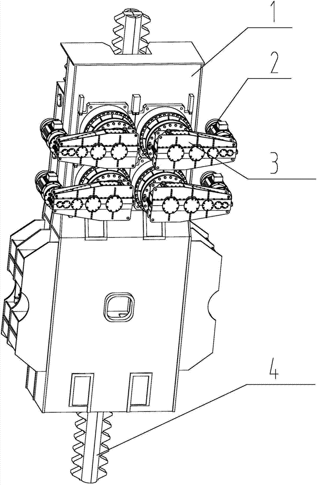
图1为本发明的立体结构示意图; Fig. 1 is the three-dimensional structure schematic diagram of the present invention;
图2为减速装置的内部结构图。 Figure 2 is an internal structural diagram of the reduction gear.
图中标记:1-桩箱,2-电机,3-减速装置,4-桩腿齿条,50-行星齿轮减速机输入轴,51-一级行星减速,52-二级行星减速,60-斜齿轮减速机输入轴,61-一级斜齿减速,62-二级斜齿减速,63-三级斜齿减速,64-四级斜齿减速。 Marks in the figure: 1-pile box, 2-motor, 3-reduction device, 4-leg rack, 50-input shaft of planetary gear reducer, 51-first-level planetary reduction, 52-secondary planetary reduction, 60- Helical gear reducer input shaft, 61-first-stage helical gear reduction, 62-two-stage helical gear reduction, 63-three-stage helical gear reduction, 64-four-stage helical gear reduction. the
具体实施方式 Detailed ways
下面结合试验例及具体实施方式对本发明作进一步的详细描述。但不应将此理解为本发明上述主题的范围仅限于以下的实施例,凡基于本发明内容所实现的技术均属于本发明的范围。 The present invention will be further described in detail below in conjunction with test examples and specific embodiments. However, it should not be understood that the scope of the above subject matter of the present invention is limited to the following embodiments, and all technologies realized based on the content of the present invention belong to the scope of the present invention.
实施例1 Example 1
结合图1和图2,本发明包括桩箱1及减速装置3,减速装置3包括斜齿轮减速机和行星齿轮减速机,电机2与斜齿轮减速机输入轴60连接,经过一级斜齿减速61、二级斜齿减速62、三级斜齿减速63和四级斜齿减速64将扭矩输出至行星齿轮减速机输入轴50,行星齿轮减速机经过一级行星减速51和二级行星减速52将扭矩输通过抬升齿轮输送至桩腿齿条4,桩腿齿条4连接桩腿,桩腿升降即带动平台升降。所述抬升齿轮和桩腿齿条4设置在桩箱1内。所述斜齿轮减速机、所述行星齿轮减速机和电机2三者组成的整体呈U形设置在桩箱1的侧面。斜齿轮减速机与行星齿轮减速机采用串联的方式。斜齿轮减速机设置在高速端,行星齿轮减速机设置在低速端。如图2所示,斜齿轮减速机采用五平行轴四级减速结构,经过四次减速增扭后通过输出轴连接所述行星齿轮减速机输入轴50。所述行星齿轮减速机采用两级减速结构且每级减速都采用三个行星轮均布于太阳轮四周的结构。
1 and 2, the present invention includes a pile box 1 and a speed reduction device 3, the speed reduction device 3 includes a helical gear reducer and a planetary gear reducer, the motor 2 is connected to the input shaft 60 of the helical gear reducer, and after a first-stage
Claims (4)
Priority Applications (1)
| Application Number | Priority Date | Filing Date | Title |
|---|---|---|---|
| CN2013102968953A CN103343800A (en) | 2013-07-16 | 2013-07-16 | Speed reducer structure of lifting type platform lifting system |
Applications Claiming Priority (1)
| Application Number | Priority Date | Filing Date | Title |
|---|---|---|---|
| CN2013102968953A CN103343800A (en) | 2013-07-16 | 2013-07-16 | Speed reducer structure of lifting type platform lifting system |
Publications (1)
| Publication Number | Publication Date |
|---|---|
| CN103343800A true CN103343800A (en) | 2013-10-09 |
Family
ID=49278620
Family Applications (1)
| Application Number | Title | Priority Date | Filing Date |
|---|---|---|---|
| CN2013102968953A Pending CN103343800A (en) | 2013-07-16 | 2013-07-16 | Speed reducer structure of lifting type platform lifting system |
Country Status (1)
| Country | Link |
|---|---|
| CN (1) | CN103343800A (en) |
Cited By (4)
| Publication number | Priority date | Publication date | Assignee | Title |
|---|---|---|---|---|
| CN104863107A (en) * | 2015-06-03 | 2015-08-26 | 上海振华重工(集团)股份有限公司 | Lifting device for cylinder type pile leg platform |
| CN108474191A (en) * | 2016-05-18 | 2018-08-31 | 大连华锐重工德国有限公司 | Rise for structure or the device fallen |
| CN109736281A (en) * | 2019-01-04 | 2019-05-10 | 武汉船用机械有限责任公司 | Gear rack lifting system |
| CN113969570A (en) * | 2020-07-23 | 2022-01-25 | 四川宏华石油设备有限公司 | Lifting device |
Citations (7)
| Publication number | Priority date | Publication date | Assignee | Title |
|---|---|---|---|---|
| FR2753466A1 (en) * | 1996-09-19 | 1998-03-20 | Brissonneau & Lotz | LIFTING SYSTEM FOR PLATFORMS |
| CN201195838Y (en) * | 2008-05-19 | 2009-02-18 | 郑州富格海洋工程装备有限公司 | Self-lifting ocean drill platform lifting and lowering mechanism |
| CN201218311Y (en) * | 2008-06-24 | 2009-04-08 | 郑州吉尔传动科技有限公司 | Load-monitoring platform lifting transmission mechanism |
| CN101629617A (en) * | 2009-07-24 | 2010-01-20 | 中远船务工程集团有限公司 | 454t lifting gearbox of self elevating offshore platform |
| CN201531018U (en) * | 2009-09-28 | 2010-07-21 | 上海振华重工(集团)股份有限公司 | Jack-up drilling platform lifting mechanism |
| CN102628264A (en) * | 2012-04-19 | 2012-08-08 | 吴平平 | Elevating device for self-elevating drilling platform |
| CN202595718U (en) * | 2012-04-19 | 2012-12-12 | 广东精铟机械有限公司 | Lifting device for self-lifting drilling platform |
-
2013
- 2013-07-16 CN CN2013102968953A patent/CN103343800A/en active Pending
Patent Citations (7)
| Publication number | Priority date | Publication date | Assignee | Title |
|---|---|---|---|---|
| FR2753466A1 (en) * | 1996-09-19 | 1998-03-20 | Brissonneau & Lotz | LIFTING SYSTEM FOR PLATFORMS |
| CN201195838Y (en) * | 2008-05-19 | 2009-02-18 | 郑州富格海洋工程装备有限公司 | Self-lifting ocean drill platform lifting and lowering mechanism |
| CN201218311Y (en) * | 2008-06-24 | 2009-04-08 | 郑州吉尔传动科技有限公司 | Load-monitoring platform lifting transmission mechanism |
| CN101629617A (en) * | 2009-07-24 | 2010-01-20 | 中远船务工程集团有限公司 | 454t lifting gearbox of self elevating offshore platform |
| CN201531018U (en) * | 2009-09-28 | 2010-07-21 | 上海振华重工(集团)股份有限公司 | Jack-up drilling platform lifting mechanism |
| CN102628264A (en) * | 2012-04-19 | 2012-08-08 | 吴平平 | Elevating device for self-elevating drilling platform |
| CN202595718U (en) * | 2012-04-19 | 2012-12-12 | 广东精铟机械有限公司 | Lifting device for self-lifting drilling platform |
Cited By (4)
| Publication number | Priority date | Publication date | Assignee | Title |
|---|---|---|---|---|
| CN104863107A (en) * | 2015-06-03 | 2015-08-26 | 上海振华重工(集团)股份有限公司 | Lifting device for cylinder type pile leg platform |
| CN108474191A (en) * | 2016-05-18 | 2018-08-31 | 大连华锐重工德国有限公司 | Rise for structure or the device fallen |
| CN109736281A (en) * | 2019-01-04 | 2019-05-10 | 武汉船用机械有限责任公司 | Gear rack lifting system |
| CN113969570A (en) * | 2020-07-23 | 2022-01-25 | 四川宏华石油设备有限公司 | Lifting device |
Similar Documents
| Publication | Publication Date | Title |
|---|---|---|
| CN205298447U (en) | Gear reduction mechanism | |
| CN201071904Y (en) | Differential planetary gearbox | |
| CN201531018U (en) | Jack-up drilling platform lifting mechanism | |
| CN101111448A (en) | Device for operating lifting structure | |
| CN202468862U (en) | Two-stage planetary gear transmission device | |
| CN202560942U (en) | Wind power speed-up box of composite planetary transmission mechanism | |
| CN102797795A (en) | Dual-shaft multistage speed reducer | |
| CN201661652U (en) | Two-axis three-stage gear reducer | |
| CN201836308U (en) | Novel duplex-gear slewing mechanism | |
| CN201461259U (en) | Speed-increasing gearbox of high-power wind driven generator | |
| CN202990503U (en) | Power drive device of lifting platform of stereo garage | |
| CN102312974B (en) | Double-output hydraulic power generation planetary speed increaser | |
| CN104421383A (en) | Speed reducing device of self-elevating drilling platform elevating system | |
| CN104121348A (en) | Closed planet structure lifting gear case of self-elevating type ocean platform | |
| CN203856973U (en) | Multistage planetary reducer for conveyor | |
| CN202228626U (en) | Dual-output planet gear speeder for hydraulic power generation | |
| CN103267088A (en) | Small-size rotary reducer for ship | |
| CN201535344U (en) | Small size and high torque reducer for rocket launch platform | |
| CN201574699U (en) | Sliding mechanism | |
| CN203270539U (en) | Self-elevating type marine drilling platform lifting device | |
| CN201902513U (en) | Walking planetary speed reducer for mining excavator | |
| CN103334416A (en) | Lifting device | |
| CN201944222U (en) | Electric hydraulic speed reducer for oil sucking machine | |
| CN202441856U (en) | Planetary device | |
| CN203560364U (en) | Split type five-planetary reducing mechanism applied to elevating system of self-elevating drilling platform |
Legal Events
| Date | Code | Title | Description |
|---|---|---|---|
| C06 | Publication | ||
| PB01 | Publication | ||
| C10 | Entry into substantive examination | ||
| SE01 | Entry into force of request for substantive examination | ||
| C12 | Rejection of a patent application after its publication | ||
| RJ01 | Rejection of invention patent application after publication |
Application publication date: 20131009 |