CN103306296A - Cutting slope frame anchor wall construction method based on soil arching effect - Google Patents
Cutting slope frame anchor wall construction method based on soil arching effect Download PDFInfo
- Publication number
- CN103306296A CN103306296A CN2013102858578A CN201310285857A CN103306296A CN 103306296 A CN103306296 A CN 103306296A CN 2013102858578 A CN2013102858578 A CN 2013102858578A CN 201310285857 A CN201310285857 A CN 201310285857A CN 103306296 A CN103306296 A CN 103306296A
- Authority
- CN
- China
- Prior art keywords
- anchor pole
- wall
- framework
- slope
- soil
- Prior art date
- Legal status (The legal status is an assumption and is not a legal conclusion. Google has not performed a legal analysis and makes no representation as to the accuracy of the status listed.)
- Granted
Links
- 239000002689 soil Substances 0.000 title claims abstract description 55
- 230000000694 effects Effects 0.000 title claims abstract description 30
- 238000010276 construction Methods 0.000 title claims abstract description 26
- 239000000463 material Substances 0.000 claims abstract description 6
- 230000003014 reinforcing effect Effects 0.000 claims description 19
- 238000004873 anchoring Methods 0.000 claims description 7
- 239000011435 rock Substances 0.000 claims description 5
- 239000011083 cement mortar Substances 0.000 claims description 4
- 230000005484 gravity Effects 0.000 claims description 4
- 238000009412 basement excavation Methods 0.000 claims description 3
- 239000004567 concrete Substances 0.000 claims description 3
- 239000011150 reinforced concrete Substances 0.000 claims description 3
- 238000007569 slipcasting Methods 0.000 claims description 3
- 239000007921 spray Substances 0.000 claims description 3
- 230000002787 reinforcement Effects 0.000 abstract description 3
- 230000003993 interaction Effects 0.000 abstract description 2
- 238000004519 manufacturing process Methods 0.000 abstract 1
- 238000000034 method Methods 0.000 abstract 1
- 238000010586 diagram Methods 0.000 description 4
- TVRCQMFDVHKZHL-UHFFFAOYSA-N 3-ethyl-3-phenyloxolan-2-one Chemical compound C=1C=CC=CC=1C1(CC)CCOC1=O TVRCQMFDVHKZHL-UHFFFAOYSA-N 0.000 description 2
- 238000005516 engineering process Methods 0.000 description 2
- 238000006467 substitution reaction Methods 0.000 description 2
- 241001074085 Scophthalmus aquosus Species 0.000 description 1
- 229910000831 Steel Inorganic materials 0.000 description 1
- 230000015572 biosynthetic process Effects 0.000 description 1
- 150000001875 compounds Chemical class 0.000 description 1
- 230000007812 deficiency Effects 0.000 description 1
- 239000004570 mortar (masonry) Substances 0.000 description 1
- 238000005096 rolling process Methods 0.000 description 1
- 239000010959 steel Substances 0.000 description 1
- 239000002699 waste material Substances 0.000 description 1
Images


Landscapes
- Pit Excavations, Shoring, Fill Or Stabilisation Of Slopes (AREA)
Abstract
The invention belongs to the technical field of geotechnical engineering and specifically relates to a cutting slope frame anchor wall construction method based on the soil arching effect. The method includes: firstly excavating slope plain stages and setting pre-reinforcement piles; calculating the length and the sectional area of anchor rods according to Coulomb active earth pressure acting on anchor walls; manufacturing the anchor rods according to the determinate length and the determinate sectional area of the anchor rods and setting anchor wall bodies; finally performing slope green protection construction. The construction method gives full consideration to interaction of structures between the piles, namely the pre-reinforcement piles can form the soil arching effect between the piles. When the frame anchor walls are constructed, the length and the sectional area of the construction anchor rods can be calculated according to the earth pressure, calculation results are accurate, engineering investment can be saved during construction, a target of safety is achieved, and materials can be saved.
Description
Technical field
The invention belongs to the geotechnical engineering technical field, be specifically related to a kind of cut slope framework anchor pole wall construction method based on soil arching effect.
Background technology
Fast-developing and diversified along with the slope supporting structure emerges a lot of light-duty retaining structures in the engineering practice, as framework anchor pole wall between pre-reinforcings stake, reinforce inter-pile soil and follow closely wall etc.But at present the problem that exists is that theoretical calculating is slightly poorer than engineering practice, as how the soil pressure that acts on retaining structure is calculated and stake-anchor-soil phase mutual effect under structure design how to calculate etc.During pre-structure design of reinforcing framework anchor pole wall between stake is constructed, pre-reinforcing stake is arranged on plain stage of slope, play the monolithic stability effect, pre-side slope soil pressure of reinforcing in the stake is calculated according to conventional enclosed pasture earth pressure gauge, because pre-reinforcing stake can form soil arching effect between stake, act on the soil pressure on the framework anchor pole between stake because the effect of " soil arching effect ", can be different with the coulomb active earth pressure that adopts in the common design.If still according to conventional calculation Design and the construction could produce very big waste.
Summary of the invention
Purpose of the present invention is exactly in order to solve the deficiency that the above-mentioned background technology exists, a kind of cut slope framework anchor pole wall construction method based on soil arching effect to be provided.
The technical solution used in the present invention is: a kind of cut slope framework anchor pole wall construction method based on soil arching effect may further comprise the steps:
(1), carry out earth rock placement and excavation at side slope surface, smooth domatic;
(2), along the side slope length direction pre-reinforcings is set at interval evenly at the next stage plain stage of slope of side slope slope body;
(3), according to the enclosed pasture earth pressure computation formula that acts on the body of wall
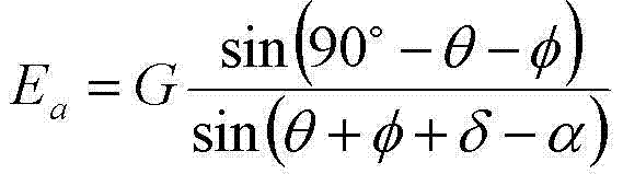
Calculate: rock-bolt length
 With anchor pole sectional area A
s=K * E
a/ f
y
(4), make anchor pole according to the rock-bolt length of determining and anchor pole sectional area;
(5), in the evenly at interval boring of side slope slope surface, the anchor pole of making inserted on the side slope bores in the good hole, and slip casting in the hole that is inserted with anchor pole, form anchor pole wall body of wall;
(6), lay green overcoat at anchor pole wall surface of wall.
In the following formula: E
aBe effect enclosed pasture active earth pressure on the wall; G is the gravity of sphenoid ABED; θ is angle of rupture; φ is soil body angle of internal friction; δ is the angle of friction between framework anchor pole wall and the soil body; α is the vertical inclination angle of framework anchor pole wall; L
aBe anchoring section length; K is safety factor; D is bolt diameter; f
RbAdhesion strength design load for cement mortar and rock hole wall; f
yTension design strength for reinforcing bar.
Further, reinforcing stake in advance in (2) in the described step is the reinforced concrete rectangular stake, and sectional dimension is 1.75 * 3.0m, and pile spacing is 5-8m.
Further, the anchor pole spacing is 3-5m in the described step (5), and is downward-sloping, with the angle of horizontal plane be 15 °-25 °.
Further, the grid-like framework that described step (6) is made of concrete in the setting of anchor pole wall surface of wall before, the width of framework is 3-5m.
Further, described green overcoat is positioned at the grid of framework, and green overcoat is linked network spray thick-layer base material or three-dimensional ecological bag.
Cut slope of the present invention adopts pre-when reinforcing between stake the framework anchor bolt construction, in view of pre-reinforcing stake can form " soil arching effect " between stake, therefore take into full account soil arching effect, soil pressure is according to the enclosed pasture earth pressure computation on the anchor pole wall, by calculating angle of rupture from the toe plane of fracture that draws, this plane of fracture and inter-pile soil arch intersect, because the arch back soil body can not produce sliding force because of the existence of soil arch and act on the anchor pole wall, then the sphenoid between the plane of fracture is the soil pressure that acts on the framework anchor pole before soil arch and the arch, framework anchor pole wall when construction thus earth pressure gauge calculate length and the sectional area of construction anchor pole, result of calculation is more accurate, can save construction investment during construction.
This constructure scheme has taken into full account the interaction of works between stake and stake, has both arrived safe target, can save material again.This constructure scheme has improved light-duty retaining structure design accuracy and the job practices of railway cut slope, has filled up the theory of computation and the construction practice of compound retaining structure.
Description of drawings
Fig. 1 is inter-pile soil arching schematic diagram of the present invention.
Fig. 2 is the soil body distribution schematic diagram behind the framework anchor pole wall of the present invention.
Fig. 3 acts on power distribution schematic diagram on the framework anchor pole wall for the present invention.
Fig. 4 vows the triangle schematic diagram for the power that the present invention acts on the framework anchor pole wall.
Fig. 5 is the construct structural representation of state of the present invention.
Fig. 6 is vertical cross-section cutaway view of the present invention.
The specific embodiment
The present invention is described in further detail below in conjunction with the drawings and specific embodiments, be convenient to be well understood to the present invention, but they do not constitute restriction to the present invention.
Cut slope based on soil arching effect of the present invention is reinforced a front baffle anchor pole wall construction method in advance, may further comprise the steps:
At first carry out plain stage of slope excavation, smooth domatic, at the next stage plain stage of slope of side slope slope body pre-reinforcings 1 is set, a pre-main reinforcement effect that plays side slope of reinforcing, pre-reinforcing stake is the reinforced concrete rectangular stake, sectional dimension is 1.75 * 3.0m, platform arranges at interval evenly that along the side slope length direction pile spacing is 5-8m in the subordinate of side slope slope body 5.
Carry out the construction of framework anchor pole wall then, at first consider " soil arching effect " of formation between stake and the stake before the construction, as shown in Figure 1, owing to can form soil arch 2 pre-the reinforcing between stake 1 following of back soil body load P effect and the stake, therefore, act on the soil pressure on the framework anchor pole between stake because the effect of " soil arching effect ", can be different with the coulomb active earth pressure that adopts in the common design.Do not considering that " soil arching effect " does the time spent between stake, the soil pressure that acts on the framework anchor pole wall is that sphenoid ABC produces, as shown in Figure 2, but in order to save material and to calculate accurately, when considering " soil arching effect ", draw the plane of fracture 7 from toe by angle of rupture and meet at the E point with the inter-pile soil arch, then the soil pressure of delta-shaped region CDE is carried on a shoulder pole by pile, the lateral earth pressure of having only sphenoid ABDE to produce acts on the framework anchor pole wall, and for the rock-bolt length of framework anchor pole wall and determining and need determining by the soil pressure that acts on the anchor pole wall of spacing, therefore need calculate the enclosed pasture active earth pressure that acts on when considering soil arching effect on the anchor pole wall, before calculating, detect anchor pole wall height H earlier, slope top surface angle of inclination beta, inter-pile soil pitch of arch h, the angle α of anchor pole wall and vertical line, angle of friction δ between anchor pole wall and the soil body and soil body internalfrictionangle.
Enclosed pasture active earth pressure concrete grammar on the anchor pole wall is as follows:
The enclosed pasture active earth pressure that acts on the wall back of the body can be tried to achieve from power arrow triangle as shown in Figure 3, Figure 4, and design formulas is:

And that G finds the solution is as follows, and note S is the area symbol, and γ is soil body unit weight, has:
Wherein:
With the counter-force E of soil body gravity G substitution wall to the soil wedge body
aObtain:
The following formula both sides to the θ differentiate, are made
, try to achieve the θ value, its substitution following formula can be tried to achieve active earth pressure E
a
In the above-mentioned formula:
E
a---effect enclosed pasture active earth pressure on the wall; G---the gravity of sphenoid ABED;
H---the inter-pile soil pitch of arch; θ---angle of rupture; Φ---soil body angle of internal friction;
δ---the angle of friction between framework anchor pole wall and the soil body; α---the vertical inclination angle of framework anchor pole wall;
β---wall top margin slope and horizontal plane angle; H---framework anchor pole wall height;
S
ADF, S
ABL, S
BEFL---the area of triangle ADF, ABL and polygon BEFL.
The enclosed pasture active earth pressure is determined sectional area and the length of anchor pole on the wall that calculates according to above-mentioned design formulas, thereby design framework anchor pole wall is more accurate, saves construction investment.
The sectional area length of anchor pole is pressed following formula and is determined:
A in the formula
s--the sectional area (mm of-reinforcing bar
2); E
a---anchor pole axial carrying enclosed pasture active earth pressure design load (N); K---load safety factor can adopt 2.0 ~ 2.2; f
y--the tension design strength (N/mm of-reinforcing bar
2).
The length of anchor pole comprises non-anchoring segment length and effective anchoring section length, and non-anchoring segment length is determined according to rib post and the actual range of the active plane of fracture or slide plane.Effectively anchoring section is determined according to following formula, and the permission adhesion stress between checking computations anchor pole and the mortar.
L in the formula
a---anchoring section length (mm); The K---safety factor can adopt 2.0 ~ 2.5; D---bolt diameter (mm); D---single steel bar diameter (mm); N---reinforcing bar radical; f
Rb--the adhesion strength design load of-cement mortar and rock hole wall; f
b--the adhesion strength design load between-cement mortar and reinforcing bar; ξ---when adopting the above reinforcing bar of two or two, the interface adhesion strength reduces coefficient, gets 0.60 ~ 0.85.
The spacing of anchor pole is generally got 2.5 ~ 4.0m.
Anchor pole wall single-stage height should not be greater than 10m.
The anchor pole reinforcing bar should be selected Ribbed Bar or high-strength finish rolling deformed bar for use, and diameter is preferably 18 ~ 32mm.
Rock-bolt length and the sectional area of determining according to aforesaid way made anchor pole at last, and with air pressure gun in the evenly boring at interval of side slope slope body 5 surfaces, the anchor pole of making is inserted in the hole that brill is good on the side slope, slip casting in the hole that is inserted with anchor pole in time, form anchor pole wall body of wall, anchor pole 6 spacings are 3-5m, and are downward-sloping, with the angle of horizontal plane be 15 °-25 °.Simultaneously, at anchor pole wall surface of wall latticed framework 3 is set, the width of framework is 3-5m, lays green overcoat 4 in the grid of anchor pole wall surface of wall framework 3, and green overcoat is linked network spray thick-layer base material or three-dimensional ecological bag.
The content that is not described in detail in this manual belongs to this area professional and technical personnel's known prior art.
Claims (5)
1. the cut slope framework anchor pole wall construction method based on soil arching effect is characterized in that, may further comprise the steps:
(1), carry out earth rock placement and excavation at side slope surface, smooth domatic;
(2), along the side slope length direction pre-reinforcings is set at interval evenly at the next stage plain stage of slope of side slope slope body;
(3), according to the enclosed pasture earth pressure computation formula that acts on the body of wall
Calculate: rock-bolt length
With anchor pole sectional area A
s=K * E
a/ f
y
(4), make anchor pole according to the rock-bolt length of determining and anchor pole sectional area;
(5), in the evenly at interval boring of side slope slope surface, the anchor pole of making inserted on the side slope bores in the good hole, and slip casting in the hole that is inserted with anchor pole, form anchor pole wall body of wall;
(6), lay green overcoat at anchor pole wall surface of wall;
In the following formula: E
aBe effect enclosed pasture active earth pressure on the wall; G is the gravity of sphenoid ABED; θ is angle of rupture; φ is soil body angle of internal friction; δ is the angle of friction between framework anchor pole wall and the soil body; α is the vertical inclination angle of framework anchor pole wall; L
aBe anchoring section length; K is safety factor; D is bolt diameter; f
RbAdhesion strength design load for cement mortar and rock hole wall; f
yTension design strength for reinforcing bar.
2. the cut slope framework anchor pole wall construction method based on soil arching effect according to claim 1 is characterized in that: reinforce stake and be the reinforced concrete rectangular stake in advance in (2) in the described step, sectional dimension is 1.75 * 3.0m, and pile spacing is 5-8m.
3. the cut slope framework anchor pole wall construction method based on soil arching effect according to claim 1 is characterized in that: the anchor pole spacing is 3-5m in the described step (5), and is downward-sloping, with the angle of horizontal plane be 15 °-25 °.
4. the cut slope framework anchor pole wall construction method based on soil arching effect according to claim 1, it is characterized in that: the grid-like framework that described step (6) is made of concrete in the setting of anchor pole wall surface of wall before, the width of framework is 3-5m.
5. the cut slope framework anchor pole wall construction method based on soil arching effect according to claim 4, it is characterized in that: described green overcoat is positioned at the grid of framework, and green overcoat is linked network spray thick-layer base material or three-dimensional ecological bag.
Priority Applications (1)
| Application Number | Priority Date | Filing Date | Title |
|---|---|---|---|
| CN201310285857.8A CN103306296B (en) | 2013-07-08 | 2013-07-08 | Cutting slope frame anchor wall construction method based on soil arching effect |
Applications Claiming Priority (1)
| Application Number | Priority Date | Filing Date | Title |
|---|---|---|---|
| CN201310285857.8A CN103306296B (en) | 2013-07-08 | 2013-07-08 | Cutting slope frame anchor wall construction method based on soil arching effect |
Publications (2)
| Publication Number | Publication Date |
|---|---|
| CN103306296A true CN103306296A (en) | 2013-09-18 |
| CN103306296B CN103306296B (en) | 2015-05-27 |
Family
ID=49131982
Family Applications (1)
| Application Number | Title | Priority Date | Filing Date |
|---|---|---|---|
| CN201310285857.8A Active CN103306296B (en) | 2013-07-08 | 2013-07-08 | Cutting slope frame anchor wall construction method based on soil arching effect |
Country Status (1)
| Country | Link |
|---|---|
| CN (1) | CN103306296B (en) |
Cited By (7)
| Publication number | Priority date | Publication date | Assignee | Title |
|---|---|---|---|---|
| CN104153378A (en) * | 2014-08-06 | 2014-11-19 | 深圳万向泰富环保科技有限公司 | Soil slope protecting wall and protecting method thereof |
| CN104631432A (en) * | 2015-01-16 | 2015-05-20 | 兰州理工大学 | Flexible supporting system for prestress anchor supporting plate of sheet-pile retaining wall and construction method |
| CN107119700A (en) * | 2017-07-03 | 2017-09-01 | 四川农业大学 | A kind of slope reinforcement and ecological protection system |
| CN109537605A (en) * | 2018-11-21 | 2019-03-29 | 滨州学院 | A kind of multiple arch side slope pays protection structure and its construction method in advance |
| CN110249813A (en) * | 2019-07-15 | 2019-09-20 | 大连地拓环境科技有限公司 | Method for greening high and steep rocky slope in mining pit |
| CN114810097A (en) * | 2022-05-27 | 2022-07-29 | 中国电建集团成都勘测设计研究院有限公司 | Method for determining maximum fracture angle of brittle rock body in high or ultrahigh ground stress area |
| CN120990060A (en) * | 2025-10-22 | 2025-11-21 | 四川能投云电科技有限公司 | A slope protection device and construction method for water conservancy and hydropower projects |
Citations (3)
| Publication number | Priority date | Publication date | Assignee | Title |
|---|---|---|---|---|
| JP2007291707A (en) * | 2006-04-25 | 2007-11-08 | Nishi Nippon Spc Kk | Embankment structure and construction method thereof |
| CN102277875A (en) * | 2011-05-09 | 2011-12-14 | 中铁二院工程集团有限责任公司 | Composite supporting structure between piles |
| CN202610808U (en) * | 2012-03-15 | 2012-12-19 | 十九冶成都建设有限公司 | Foundation Pit Supporting Structure Combined with Capping Pressure, Anchorage and Side Block |
-
2013
- 2013-07-08 CN CN201310285857.8A patent/CN103306296B/en active Active
Patent Citations (3)
| Publication number | Priority date | Publication date | Assignee | Title |
|---|---|---|---|---|
| JP2007291707A (en) * | 2006-04-25 | 2007-11-08 | Nishi Nippon Spc Kk | Embankment structure and construction method thereof |
| CN102277875A (en) * | 2011-05-09 | 2011-12-14 | 中铁二院工程集团有限责任公司 | Composite supporting structure between piles |
| CN202610808U (en) * | 2012-03-15 | 2012-12-19 | 十九冶成都建设有限公司 | Foundation Pit Supporting Structure Combined with Capping Pressure, Anchorage and Side Block |
Non-Patent Citations (2)
| Title |
|---|
| 吴昌将等: ""边坡工程中抗滑桩群桩土拱效应的数值分析"", 《地下空间与工程学报》 * |
| 李涛等: ""考虑土拱效应的土压力理论在桩锚支护受力分析中的应用"", 《四川建筑科学研究》 * |
Cited By (10)
| Publication number | Priority date | Publication date | Assignee | Title |
|---|---|---|---|---|
| CN104153378A (en) * | 2014-08-06 | 2014-11-19 | 深圳万向泰富环保科技有限公司 | Soil slope protecting wall and protecting method thereof |
| CN104153378B (en) * | 2014-08-06 | 2016-06-29 | 深圳万向泰富环保科技有限公司 | Soil-slope protecting wall and means of defence thereof |
| CN104631432A (en) * | 2015-01-16 | 2015-05-20 | 兰州理工大学 | Flexible supporting system for prestress anchor supporting plate of sheet-pile retaining wall and construction method |
| CN104631432B (en) * | 2015-01-16 | 2017-02-22 | 兰州理工大学 | Flexible supporting system for prestress anchor supporting plate of sheet-pile retaining wall and construction method thereof |
| CN107119700A (en) * | 2017-07-03 | 2017-09-01 | 四川农业大学 | A kind of slope reinforcement and ecological protection system |
| CN109537605A (en) * | 2018-11-21 | 2019-03-29 | 滨州学院 | A kind of multiple arch side slope pays protection structure and its construction method in advance |
| CN110249813A (en) * | 2019-07-15 | 2019-09-20 | 大连地拓环境科技有限公司 | Method for greening high and steep rocky slope in mining pit |
| CN110249813B (en) * | 2019-07-15 | 2021-05-25 | 大连地拓环境科技有限公司 | A greening method for high and steep rocky slopes in mining pits |
| CN114810097A (en) * | 2022-05-27 | 2022-07-29 | 中国电建集团成都勘测设计研究院有限公司 | Method for determining maximum fracture angle of brittle rock body in high or ultrahigh ground stress area |
| CN120990060A (en) * | 2025-10-22 | 2025-11-21 | 四川能投云电科技有限公司 | A slope protection device and construction method for water conservancy and hydropower projects |
Also Published As
| Publication number | Publication date |
|---|---|
| CN103306296B (en) | 2015-05-27 |
Similar Documents
| Publication | Publication Date | Title |
|---|---|---|
| CN103306296B (en) | Cutting slope frame anchor wall construction method based on soil arching effect | |
| CN203476347U (en) | Preliminary bracing device for collapsible loess tunnel | |
| CN104481552B (en) | Super-huge karst cave hole roof fall stone protection construction method | |
| CN106930271A (en) | It is a kind of to excavate the continuous side wall supporting and retaining system protective construction in underground and its construction method without fertile groove | |
| CN104018490B (en) | A kind of Z-shaped square-section friction pile and construction method thereof | |
| CN111910679B (en) | Construction method of super-long and super-balanced retaining wall under complex terrain | |
| CN107354953B (en) | Concrete rib band and the reinforced Retaining wall structure of intensive aspect and construction method | |
| CN206941608U (en) | A kind of diaphram wall foundation pit supporting construction | |
| CN106522270A (en) | Pile foundation and retaining wall anti-earthquake retaining structure comprising EPS buffer layers and construction method | |
| CN205576940U (en) | Compound retaining structure of friction pile that pile bolck is connected entirely | |
| CN104762978A (en) | Anchor rod gravity retaining wall for high slope support and manufacturing method | |
| CN104120736A (en) | Construction method of reinforced concrete retaining wall | |
| CN107119699A (en) | A kind of friction pile and its construction method based on the beam of uniform strength | |
| CN203383508U (en) | One-sided formwork body structure backing onto brick concrete retaining wall | |
| CN211571778U (en) | Miniature pile retaining wall | |
| CN103388337A (en) | Cut slope pre-reinforced pile construction method based on soil arch effect | |
| CN218439399U (en) | Auxiliary supporting device for tunnel inverted arch construction | |
| CN206800370U (en) | It is a kind of to excavate the continuous side wall supporting and retaining system protective construction in underground without fertile groove | |
| CN203284795U (en) | Buttressed retaining wall with anchor board | |
| CN214460560U (en) | A foundation reinforcement structure | |
| CN109356104A (en) | Temporary traffic corridor structure and its construction method in the whole period | |
| CN204877494U (en) | Soft rock tunnel portal reinforced structure | |
| CN108914947A (en) | Foundation pit anchor wall draws the construction method of anchor supporting and its supporting construction of drilling tool and formation | |
| CN204753603U (en) | Supporting construction is deepened again to deep basal pit | |
| CN108951654A (en) | Different cutting depth basement construction method for supporting |
Legal Events
| Date | Code | Title | Description |
|---|---|---|---|
| C06 | Publication | ||
| PB01 | Publication | ||
| C10 | Entry into substantive examination | ||
| SE01 | Entry into force of request for substantive examination | ||
| C14 | Grant of patent or utility model | ||
| GR01 | Patent grant |