CN103284440A - Vertical air guide type blowing barrel and blowing device composed of vertical air guide type blowing barrel - Google Patents
Vertical air guide type blowing barrel and blowing device composed of vertical air guide type blowing barrel Download PDFInfo
- Publication number
- CN103284440A CN103284440A CN2013102447922A CN201310244792A CN103284440A CN 103284440 A CN103284440 A CN 103284440A CN 2013102447922 A CN2013102447922 A CN 2013102447922A CN 201310244792 A CN201310244792 A CN 201310244792A CN 103284440 A CN103284440 A CN 103284440A
- Authority
- CN
- China
- Prior art keywords
- air
- tube
- hair
- annular
- dryer
- Prior art date
- Legal status (The legal status is an assumption and is not a legal conclusion. Google has not performed a legal analysis and makes no representation as to the accuracy of the status listed.)
- Granted
Links
Images


Abstract
The invention discloses a vertical air guide type blowing barrel and a blowing device composed of the vertical air guide type blowing barrel. The vertical air guide type blowing barrel comprises a blowing barrel body which comprises an inner barrel and an outer barrel. The upper end between the inner barrel and the outer barrel is provided with a closed upper end edge. The lower end between the inner barrel and the outer barrel is provided with an annular air outlet. The top circle of the outer barrel vertically extends upward to form a connecting barrel part. The connecting barrel part is connected with the air outlet end of a blower. An air inlet cavity is formed inside the connecting barrel body and is connected with an air outlet pipeline of the blower. The vertical air guide type blowing barrel enables air currents from the blower to be in the same direction as a handle of the blower and be capable of being blown downward, so that operation is easy and the fatigue of a user is reduced. The air currents are blown from top to bottom, so that the cuticle of hair can not be damaged, and the hair is protected to be healthy and have luster. Further, through the further arrangement of a movable barrel, an air door structure and a blinker, the directly downward direction, the anticlockwise spirally downward direction and the clockwise spirally downward direction of air currents can be realized, so that different hair styles can be made.
Description
Technical field
The present invention relates to a kind of barrel structure that blows of hair-dryer, more particularly refer to a kind of vertical air-guiding blow the tube and by its blowing device that constitutes.
Background technology
In the prior art, hair-dryer is generally right angle (or near right angle) type structure, and the user holds the Handheld Division of below, and the air-out direction of hair-dryer then is rectangular in shape with the Handheld Division direction; For easy to operate, the Handheld Division is generally vertical direction, and the air-out direction of hair-dryer then is horizontal direction.No matter be to send out for others' blow head, still to send out for own blow head, the air-out direction of hair-dryer all is laterally to blow to hair; The hair tonic direction of this and hair is inequality, especially women's long hair.Because the cuticula of every hair is to be the phosphorus laminated structure from root of hair to sending out the tip, laterally dries facing to hair, damages the cuticula of hair easily, thereby causes the over-drying or jag of hair, even damage hair.
Though, the barrel structure that blows that has some to be used for hair-dryer in the prior art, however these structure great majority all are simple horn mouth structures, or collect the flat tuyere structure that wind is used.
Therefore, be necessary to develop the barrel structure that blows that makes new advances, make hair in the process that dries up, can protect hair better.
Summary of the invention
The objective of the invention is to overcome the defective of prior art, provide a kind of vertical air-guiding blow the tube and by its blowing device that constitutes.
For achieving the above object, the present invention is by the following technical solutions:
A kind of vertical air-guiding blows tube, comprises blowing a body, and a described body that blows comprises inner core and urceolus, and the upper end between inner core and the urceolus is provided with the limit, upper end of sealing, and the lower end between inner core and the urceolus is annular air outlet; Outwards vertically extend the coupling tunnel portion that is provided with on the cylindrical of described urceolus; Described coupling tunnel portion connects with the outlet air end of hair-dryer; Be air-inlet cavity in the coupling tunnel portion, described air-inlet cavity connects with the air outlet pipeline of hair-dryer.
Its further technical scheme is: be provided with movable tube between described inner core and the urceolus, described inner core is provided with several fixed throttles, described movable tube is provided with movable air door, also comprises the rotary handle for registration between adjusting activity air door and the fixed throttle; Described rotary handle and movable tube driving coupling.
Its further technical scheme is: described coupling tunnel portion is that removable activity connects with hair-dryer; The outlet air end of hair-dryer is provided with cannelure, and coupling tunnel portion is provided with the card hook part that is embedded in the cannelure, reaches the back-moving spring that resets for card hook part and is used for making card hook part to break away from the grab button of cannelure.
Its further technical scheme is: described movable tube extends upward and is provided with push rod, and described push rod constitutes described rotary handle; Limit, described upper end is provided be used to the push-rod hole that passes push rod, and described push rod and push-rod hole are one or two.
Its further technical scheme is: the outer side edges of described movable tube is provided with blinker; When described movable tube was in the different rotary angle, the air-out airflow direction of blinker and hair-dryer was different angles, to regulate the airflow direction of annular air outlet.
Its further technical scheme is: when described movable air door all overlapped with fixed throttle, full trrottle, blinker were positioned at the right side of air-out airflow direction, and the air-out air-flow enters the annular chamber between inner core and the urceolus from the left side, form clockwise screw downstream; When described movable air door did not all overlap with fixed throttle, air door contract fully, blinker were positioned at the left side of air-out airflow direction, and the air-out air-flow enters the annular chamber between inner core and the urceolus from the right side, form counterclockwise screw downstream; Described movable air door overlaps a half with fixed throttle, air door is semi-closed, and blinker is positioned at the centre of air-out airflow direction, and the air-out air-flow enters the annular chamber between inner core and the urceolus simultaneously from left side and right side, form air-flow vertically downward.
A kind of have vertical air-guiding blow the tube blowing device, comprise hair-dryer, the outlet air end of described hair-dryer is connected with aforesaid vertical air-guiding and blows tube.
Its further technical scheme is: be provided with movable tube between described inner core and the urceolus, described inner core is provided with several fixed throttles, described movable tube is provided with movable air door, also comprises the rotary handle for registration between adjusting activity air door and the fixed throttle; Described rotary handle and movable tube driving coupling; Described rotary handle comprises the handle portion of being located at the annular solid in the outlet air end and being located at the annular solid outside; Described outlet air end is provided with the annular housing for the holding ring body, and the outside of described annular housing is provided be used to the handle groove that passes handle portion; Described annular housing end face is provided with annular tooth part, and described movable tube is provided with toothed region, described annular tooth part and toothed region driving coupling.
Its further technical scheme is: described coupling tunnel portion is that removable activity connects with hair-dryer; The outlet air end of hair-dryer is provided with cannelure, and coupling tunnel portion is provided with the card hook part that is embedded in the cannelure, reaches the back-moving spring that resets for card hook part and is used for making card hook part to break away from the grab button of cannelure.
Its further technical scheme is: described annular solid is provided with locating slot, described outlet air end is provided with positioning lever, described positioning lever the inner is embedded in the locating slot, and be provided with for the retainer spring that positioning lever the inner is pressed in the locating slot, described positioning lever outer end is positioned at the fit connection place of outlet air end and coupling tunnel portion; When described vertical air-guiding blew tube and connects with outlet air end, coupling tunnel portion pushed down the positioning lever outer end, positioning lever the inner perk, and the locating slot of disengaging annular solid is used the hand propelled handle portion, and annular solid rotates at annular housing; Described outlet air end is not connected with vertical air-guiding when blowing tin, and retainer spring is pressed into the locating slot of annular solid with positioning lever the inner, and annular solid is fixed in the annular housing.
The present invention's beneficial effect compared with prior art is: the present invention blows tube and utilizes the annular air-flow path that forms between inner core and the urceolus; make air-flow that hair-dryer comes out by original directly producing by boasting; through after the vertical water conservancy diversion; become the direction identical with the hair-dryer handle; can blow to people's head vertically downward; easy operating; reduce user's fatigue; air-flow blows to hair from top to bottom; its direction is that the cuticula on hair is blown to sending out the tip by root of hair; make the hair cuticula can be not impaired, protection hair healthy and glossy.In addition, by movable tube and the air door structure that increases, and the blinker structure, can be by angle after adjusting activity tube and the inner core, realize under downward, the counterclockwise screw of craspedodrome and three kinds of airflow directions under the clockwise screw, with the hair style for the manufacture of different shaping.By hook structure, realized blowing tube and connected with the removable of hair-dryer, be easy to installation and the production of product, after using, also be easy to cleaning and maintenance.Hair-dryer has adopted ring channel structures, makes that the angle that connects blow tube and hair-dryer can 360 degree rotations, by the quick formula operation of button, can regulate an angle of blowing tin with hair-dryer in the use at any time.
Below in conjunction with the drawings and specific embodiments the present invention is further described.
Description of drawings
Fig. 1 blows the structural representation of a specific embodiment one for a kind of vertical air-guiding of the present invention;
Figure 1A is the vertical view (arrow is airflow direction among the figure) of Fig. 1;
Fig. 2 blows the structural representation (employing activity barrel structure and air door structure) of a specific embodiment two for a kind of vertical air-guiding of the present invention;
Fig. 3 A is the vertical view (full trrottle state) of Fig. 2;
Fig. 3 B is the vertical view (the half-open semi-closed state of air door) of Fig. 2;
Fig. 3 C is the vertical view (air door full closing state) of Fig. 2;
Fig. 4 has the specific embodiment stereogram that vertical air-guiding blows the blowing device of tube for the present invention is a kind of;
Fig. 5 has the stereogram of another angle of specific embodiment that vertical air-guiding blows the blowing device of tube for the present invention is a kind of;
Fig. 6 has the stereogram of the another angle of specific embodiment that vertical air-guiding blows the blowing device of tube for the present invention is a kind of;
Fig. 7 has the cutaway view (blow tube and outlet air end part) of specific embodiment that vertical air-guiding blows the blowing device of tube for the present invention is a kind of.
Fig. 8 has the partial perspective view (removing blowing barrel structure and removing the outlet air end part of shell of urceolus) of specific embodiment that vertical air-guiding blows the blowing device of tube for the present invention is a kind of;
Fig. 9 has vertical air-guiding and blows movable tube stereogram in the specific embodiment of blowing device of tube for the present invention is a kind of.
Reference numeral
10 blow a body 11 inner cores
111 fixed throttles, 12 urceolus
Limit, 13 upper end 14 annular air outlets
15 coupling tunnel portions, 151 air-inlet cavities
19 movable tube 191 movable air doors
192 blinkers, 193 push rods
20 hair-dryers, 21 outlet air ends
22 air outlets
40 blow tube 41 inner cores
411 fixed throttles, 42 urceolus
45 coupling tunnel portions, 451 card hook parts
452 back-moving springs, 453 grab buttons
49 movable tube 491 movable air doors
492 toothed region, 493 blinkers
494 air vents, 50 hair-dryers
51 outlet air ends, 511 cannelures
512 toothed region, 518 handle grooves
519 annular housings, 59 fit connection places
60 rotary handles, 61 annular solids
611 locating slots, 62 handle portion
63 annular tooth parts, 70 travelling gears
80 detent mechanisms, 82 positioning levers
83 retainer springs, 454 clamping hook seats
450 grab assemblies, 412 annular air outlets
48 show the hole
The specific embodiment
In order to more fully understand technology contents of the present invention, below in conjunction with specific embodiment technical scheme of the present invention is further introduced and explanation, but be not limited to this.
Specific embodiment one shown in Fig. 1 to Figure 1A, a kind of vertical air-guiding of the present invention blows tube; Comprise and blow a body 10, blow a body 10 and comprise inner core 11 and urceolus 12, the upper end between inner core 11 and the urceolus 12 is provided with the limit, upper end 13 of sealing, and the lower end between inner core 11 and the urceolus 12 is annular air outlet 14; Outwards vertically extend the coupling tunnel portion 15 that is provided with on the cylindrical of urceolus 12; Coupling tunnel portion 15 connects with the outlet air end 21 of hair-dryer 20; Be air-inlet cavity 151 in the coupling tunnel portion 15, air-inlet cavity 151 connects with air outlet 22 pipelines of hair-dryer 20.The air-flow of hair-dryer air outlet stops through inner core, enters in the circulating line between inner core and the urceolus, because the limit, upper end is sealed, air-flow can only be discharged from the annular air outlet of lower end.Because annular air outlet has air-flow rapidly to flow downward; the center cavity that also can drive inner core simultaneously has air-flow flowing from top to bottom; make blow the air of hair not only from the air-flow in the hair-dryer; also has the air-flow from top to bottom that forms in the atmosphere; be conducive to mix the thermal current that hair-dryer comes out like this; help to protect hair not by over-drying, thereby the protection hair is difficult for impaired.
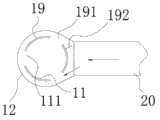
In the specific embodiment two shown in Fig. 2 to Fig. 3 C, between inner core 11 and urceolus 12, be provided with the movable jacket casing of movable tube 19(on inner core), inner core 11 is provided with 3 fixed throttles 111, movable tube 19 is provided with three movable air doors 191, also comprises the rotary handle for registration between adjusting activity air door 191 and the fixed throttle 111; Rotary handle and movable tube 19 driving coupling.Movable tube 19 extends upward and is provided with push rod 193, and push rod 193 constitutes described rotary handle; Limit 13, upper end is provided be used to the push-rod hole (not shown) of passing push rod 193, and push rod 193 and push-rod hole are two.Movable tube 19 outer side edges near hair-dryer are provided with blinker 192; When movable tube 19 was in the different rotary angle, blinker 192 was different angles with the air-out airflow direction of hair-dryer 20, to regulate the airflow direction of annular air outlet:
As shown in Figure 3A, when movable air door 191 all overlaps with fixed throttle 111, full trrottle, blinker 192 is positioned at the right side of air-out airflow direction, and the air-out air-flow enters the annular chamber between inner core and the urceolus from the left side, form clockwise screw downstream;
Shown in Fig. 3 B, when movable air door 191 does not all overlap with fixed throttle 111, the air door contract fully, blinker 192 is positioned at the left side of air-out airflow direction, and the air-out air-flow enters the annular chamber between inner core and the urceolus from the right side, form counterclockwise screw downstream;
Shown in Fig. 3 C, movable air door overlaps a half with fixed throttle, and air door is semi-closed, and blinker 192 is positioned at the centre of air-out airflow direction, and the air-out air-flow enters the annular chamber between inner core and the urceolus simultaneously from left side and right side, form air-flow vertically downward.
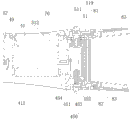
To the specific embodiment shown in Figure 9, provided that the present invention is a kind of to have a concrete structure that vertical air-guiding blows the blowing device of tube as Fig. 4; It comprises blows tube 40 and hair-dryer 50, and the coupling tunnel portion 45 of blowing tube 40 and hair-dryer 50 connect for removable activity; The outlet air end 51 of hair-dryer 50 is provided with cannelure 511, and coupling tunnel portion 45 is provided with the card hook part 451 that is embedded in the cannelure 511, reaches the back-moving spring 452 that resets for card hook part 451 and is used for making card hook part 451 to break away from the grab button 453 of cannelures 511.Wherein, card hook part 451, back-moving spring 452 and grab button 453 form a grab assembly 450(and are fixed on the urceolus by clamping hook seat 454), be provided with two in the present embodiment, and be in symmetrical position.During use, press two grab buttons, can take off from hair-dryer blowing tube, perhaps allow and blow tube and be at any angle with hair-dryer and connect.In order to allow blowing tube and can optionally not rotate with hair-dryer in the use, bottom land at cannelure 511 is provided with the toothed region corresponding with the end of card hook part 512, make after the release catch button, under the effect of back-moving spring, the end of card hook part is embedded on the toothed region, makes to blow connecting of tube and hair-dryer, can not axial withdrawal, can not rotate movement, form reliable connecting relation.
Be provided with movable tube 49 between inner core 41 and the urceolus 42, inner core 41 is provided with 3 fixed throttles 411.Movable tube 49 is provided with 3 movable air doors 491, also comprises the rotary handle 60 for registration between adjusting activity air door 491 and the fixed throttle 411; Rotary handle 60 and movable tube 49 driving coupling; Rotary handle comprises the annular solid of being located in the outlet air end 61 and the handle portion 62 of being located at annular solid 61 outsides; Outlet air end 51 is provided with the annular housing 519 for holding ring body 61, and the outside of annular housing 519 is provided be used to the handle groove 518 that passes handle portion 62; Annular solid 61 end faces are provided with annular tooth part 63, and movable tube 49 is provided with toothed region 492, annular tooth part 63 and toothed region 492 driving coupling.Because the toothed region apart from each other of annular tooth part and movable tube, need to adopt the gear of middle transition to realize driving coupling, so, in the present embodiment, the direction of two grab assemblies is identical with the concentric axis direction of the movable tube of inner core urceolus, one of them grab assembly is positioned at the side of the toothed region 492 of movable tube 49, on this grab assembly, just be arranged with a travelling gear 70, travelling gear 70 has been realized the driving coupling between the toothed region of the annular tooth part of rotary handle and movable tube well, just utilized simultaneously one of them grab assembly, optimize mechanism generally, save manufacturing cost, and operation and maintenance is got up all very convenient.
Because blowing tube can remove from hair-dryer at any time, there is certain tooth matching angle relation and blow between the movable tube of tube and the rotary handle, to blow tube after hair-dryer is taken off, should guarantee that rotary handle is difficult for rotating, assemble with original position of rotation with realization, for this reason, increased detent mechanism 80.This detent mechanism is included in the locating slot 611 that annular solid 61 is provided with, the positioning lever 82 that is provided with at outlet air end 51, positioning lever 82 the inners are embedded in the locating slot 611, and be provided with for the retainer spring 83 that positioning lever 82 the inners is pressed in the locating slot 611, positioning lever 82 outer ends are positioned at the fit connection place 59 of outlet air end 51 and coupling tunnel portion 45; When blowing tube 40 and connecting with outlet air end 51, coupling tunnel portion 45 pushes down positioning lever 82 outer ends, positioning lever 82 inner perks, the locating slot 611 that breaks away from annular solid 61, at this moment, rotary handle is in movable state, with hand propelled handle portion 62, annular solid 61 can rotate in annular housing 519, and then the rotation of promotion activity tube; Outlet air end 51 is not connected with and blew tube at 40 o'clock, and retainer spring 83 is pressed into the locating slot 611 of annular solid 61 with positioning lever 82 the inners, and annular solid 61 is fixed in the annular housing 519, can not rotate, and movable tube can not rotate.The regulative mode of movable air door in the present embodiment with blow a specific embodiment two in structure identical.In the present embodiment, also being provided with blinker 493(on the movable tube 49 is T type structure).Movable tube 49 also is provided with four air vents 494 below blinker 493.In order to allow the movable air duct situation that the user can understanding activity tube, be provided with on the limit, upper end of blowing tube (being urceolus) and show hole 48, can see that a movable tube upper surface is printed on pointing character or indicator collet from showing the hole, thereby know the residing position of rotation of movable tube.In use, in the time will blowing tube and remove from hair-dryer, grab assembly 450 need be pressed, at this moment, blinker can produce interference if be between individual grab assembly, can't press the grab button, therefore, in the time will blowing tube and remove from hair-dryer, need allow rotary handle 60 be pushed into Far Left (being that positioning lever 82 the inners are embedded in the locating slot 611).
In other embodiment, movable air door, fixed throttle also can all be two or four.
In other embodiment, rotary handle also can be contained on the cylindrical sidewall of urceolus.
In other embodiment, in blowing device, also can adopt the barrel structure that blows that only has urceolus and inner core.
In sum; the present invention blows tube and utilizes the annular air-flow path that forms between inner core and the urceolus, makes air-flow that hair-dryer comes out by original directly producing by boasting, through after the vertical water conservancy diversion; become the direction identical with the hair-dryer handle; can blow to people's head vertically downward, easy operating, minimizing user's fatigue; air-flow blows to hair from top to bottom; its direction is that the cuticula on hair is blown to sending out a tip by root of hair, makes the hair cuticula can be not impaired, protection hair healthy and glossy.In addition, by movable tube and the air door structure that increases, and the blinker structure, can be by angle after adjusting activity tube and the inner core, realize under downward, the counterclockwise screw of craspedodrome and three kinds of airflow directions under the clockwise screw, with the hair style for the manufacture of different shaping.By hook structure, realized blowing tube and connected with the removable of hair-dryer, be easy to installation and the production of product, after using, also be easy to cleaning and maintenance.Hair-dryer has adopted ring channel structures, makes that the angle that connects blow tube and hair-dryer can 360 degree rotations, by the quick formula operation of button, can regulate an angle of blowing tin with hair-dryer in the use at any time.
Above-mentionedly only further specify technology contents of the present invention with embodiment, so that the reader is more readily understood, do not only limit to this but do not represent embodiments of the present invention, any technology of doing according to the present invention is extended or recreation, all is subjected to protection of the present invention.Protection scope of the present invention is as the criterion with claims.
Claims (10)
1. a vertical air-guiding blows tube, comprises and blows a body, it is characterized in that a described body that blows comprises inner core and urceolus, and the upper end between inner core and the urceolus is provided with the limit, upper end of sealing, and the lower end between inner core and the urceolus is annular air outlet; Outwards vertically extend the coupling tunnel portion that is provided with on the cylindrical of described urceolus; Described coupling tunnel portion connects with the outlet air end of hair-dryer; Be air-inlet cavity in the coupling tunnel portion, described air-inlet cavity connects with the air outlet pipeline of hair-dryer.
2. a kind of vertical air-guiding according to claim 1 blows tube, it is characterized in that being provided with between described inner core and the urceolus movable tube, described inner core is provided with several fixed throttles, described movable tube is provided with movable air door, also comprises the rotary handle for registration between adjusting activity air door and the fixed throttle; Described rotary handle and movable tube driving coupling.
3. a kind of vertical air-guiding according to claim 1 blows tube, it is characterized in that described coupling tunnel portion is that removable activity connects with hair-dryer; The outlet air end of hair-dryer is provided with cannelure, and coupling tunnel portion is provided with the card hook part that is embedded in the cannelure, reaches the back-moving spring that resets for card hook part and is used for making card hook part to break away from the grab button of cannelure.
4. a kind of vertical air-guiding according to claim 2 blows tube, it is characterized in that described movable tube extends upward to be provided with push rod, and described push rod constitutes described rotary handle; Limit, described upper end is provided be used to the push-rod hole that passes push rod, and described push rod and push-rod hole are one or two.
5. a kind of vertical air-guiding according to claim 2 blows tube, it is characterized in that the outer side edges of described movable tube is provided with blinker; When described movable tube was in the different rotary angle, the air-out airflow direction of blinker and hair-dryer was different angles, to regulate the airflow direction of annular air outlet.
6. a kind of vertical air-guiding according to claim 5 blows tube, when it is characterized in that described movable air door all overlaps with fixed throttle, full trrottle, blinker is positioned at the right side of air-out airflow direction, the air-out air-flow enters the annular chamber between inner core and the urceolus from the left side, form clockwise screw downstream; When described movable air door did not all overlap with fixed throttle, air door contract fully, blinker were positioned at the left side of air-out airflow direction, and the air-out air-flow enters the annular chamber between inner core and the urceolus from the right side, form counterclockwise screw downstream; Described movable air door overlaps a half with fixed throttle, air door is semi-closed, and blinker is positioned at the centre of air-out airflow direction, and the air-out air-flow enters the annular chamber between inner core and the urceolus simultaneously from left side and right side, form air-flow vertically downward.
7. one kind has the blowing device that vertical air-guiding blows tube, comprises hair-dryer, and the outlet air end that it is characterized in that described hair-dryer is connected with the described vertical air-guiding of claim 1 and blows tube.
According to claim 7 a kind of have vertical air-guiding blow the tube blowing device, it is characterized in that being provided with between described inner core and the urceolus movable tube, described inner core is provided with several fixed throttles, described movable tube is provided with movable air door, also comprises the rotary handle for registration between adjusting activity air door and the fixed throttle; Described rotary handle and movable tube driving coupling; Described rotary handle comprises the handle portion of being located at the annular solid in the outlet air end and being located at the annular solid outside; Described outlet air end is provided with the annular housing for the holding ring body, and the outside of described annular housing is provided be used to the handle groove that passes handle portion; Described annular solid end face is provided with annular tooth part, and described movable tube is provided with toothed region, described annular tooth part and toothed region driving coupling.
9. a kind of blowing device that vertical air-guiding blows tube that has according to claim 8 is characterized in that described coupling tunnel portion is that removable activity connects with hair-dryer; The outlet air end of hair-dryer is provided with cannelure, and coupling tunnel portion is provided with the card hook part that is embedded in the cannelure, reaches the back-moving spring that resets for card hook part and is used for making card hook part to break away from the grab button of cannelure.
According to claim 9 a kind of have vertical air-guiding blow the tube blowing device, it is characterized in that described annular solid is provided with locating slot, described outlet air end is provided with positioning lever, described positioning lever the inner is embedded in the locating slot, and be provided with for the retainer spring that positioning lever the inner is pressed in the locating slot, described positioning lever outer end is positioned at the fit connection place of outlet air end and coupling tunnel portion; When described vertical air-guiding blew tube and connects with outlet air end, coupling tunnel portion pushed down the positioning lever outer end, positioning lever the inner perk, and the locating slot of disengaging annular solid is used the hand propelled handle portion, and annular solid rotates at annular housing; Described outlet air end is not connected with vertical air-guiding when blowing tin, and retainer spring is pressed into the locating slot of annular solid with positioning lever the inner, and annular solid is fixed in the annular housing.
Priority Applications (1)
| Application Number | Priority Date | Filing Date | Title |
|---|---|---|---|
| CN201310244792.2A CN103284440B (en) | 2013-06-19 | 2013-06-19 | Vertical air guide type blowing barrel and blowing device composed of vertical air guide type blowing barrel |
Applications Claiming Priority (1)
| Application Number | Priority Date | Filing Date | Title |
|---|---|---|---|
| CN201310244792.2A CN103284440B (en) | 2013-06-19 | 2013-06-19 | Vertical air guide type blowing barrel and blowing device composed of vertical air guide type blowing barrel |
Publications (2)
| Publication Number | Publication Date |
|---|---|
| CN103284440A true CN103284440A (en) | 2013-09-11 |
| CN103284440B CN103284440B (en) | 2015-06-17 |
Family
ID=49086407
Family Applications (1)
| Application Number | Title | Priority Date | Filing Date |
|---|---|---|---|
| CN201310244792.2A Expired - Fee Related CN103284440B (en) | 2013-06-19 | 2013-06-19 | Vertical air guide type blowing barrel and blowing device composed of vertical air guide type blowing barrel |
Country Status (1)
| Country | Link |
|---|---|
| CN (1) | CN103284440B (en) |
Cited By (9)
| Publication number | Priority date | Publication date | Assignee | Title |
|---|---|---|---|---|
| FR3026926A1 (en) * | 2014-10-13 | 2016-04-15 | Seb Sa | HAIRSTYLE HAIR ACCESSORY AND HAIRSTYLE EQUIPMENT EQUIPPED WITH SUCH AN ACCESSORY |
| WO2016059317A1 (en) | 2014-10-13 | 2016-04-21 | Seb S.A. | Open hairstyling accessory and hairstyling device with such an accessory |
| CN107259761A (en) * | 2016-04-07 | 2017-10-20 | Seb公司 | Open haircut annex and the hairdressing apparatus equipped with this annex |
| CN109645650A (en) * | 2019-01-25 | 2019-04-19 | 追觅科技(天津)有限公司 | The air guide member and hair dryer of hair dryer |
| CN110236282A (en) * | 2019-06-28 | 2019-09-17 | 新联电器厂有限公司 | Warm-air comb |
| GB2574606A (en) * | 2018-06-11 | 2019-12-18 | Dyson Technology Ltd | Attachment for a handheld appliance |
| GB2574604A (en) * | 2018-06-11 | 2019-12-18 | Dyson Technology Ltd | Attachment for a handheld appliance |
| CN114009919A (en) * | 2021-11-26 | 2022-02-08 | 珠海格力电器股份有限公司 | Tuyere subassembly reaches hairdryer including it |
| CN114481343A (en) * | 2020-10-23 | 2022-05-13 | 中国石油化工股份有限公司 | Fiber spinning method and polyethylene spinning fiber |
Citations (5)
| Publication number | Priority date | Publication date | Assignee | Title |
|---|---|---|---|---|
| US4634839A (en) * | 1985-01-07 | 1987-01-06 | Gilbertson John E | Filtered warm air drying device |
| DE3614633A1 (en) * | 1986-04-30 | 1987-11-05 | Wigo Electric Gmbh | Hair-drier |
| EP0351765A2 (en) * | 1988-07-21 | 1990-01-24 | Guido Borchardt | Hand-operated hair dryer |
| CN101384189A (en) * | 2006-01-04 | 2009-03-11 | 莱奥波尔多·马泰奥·巴齐卡卢波 | Hairdryer device |
| CN203341187U (en) * | 2013-06-19 | 2013-12-18 | 新联电器厂有限公司 | Vertical air-guide type blowing barrel and hair drier comprising same |
-
2013
- 2013-06-19 CN CN201310244792.2A patent/CN103284440B/en not_active Expired - Fee Related
Patent Citations (5)
| Publication number | Priority date | Publication date | Assignee | Title |
|---|---|---|---|---|
| US4634839A (en) * | 1985-01-07 | 1987-01-06 | Gilbertson John E | Filtered warm air drying device |
| DE3614633A1 (en) * | 1986-04-30 | 1987-11-05 | Wigo Electric Gmbh | Hair-drier |
| EP0351765A2 (en) * | 1988-07-21 | 1990-01-24 | Guido Borchardt | Hand-operated hair dryer |
| CN101384189A (en) * | 2006-01-04 | 2009-03-11 | 莱奥波尔多·马泰奥·巴齐卡卢波 | Hairdryer device |
| CN203341187U (en) * | 2013-06-19 | 2013-12-18 | 新联电器厂有限公司 | Vertical air-guide type blowing barrel and hair drier comprising same |
Cited By (17)
| Publication number | Priority date | Publication date | Assignee | Title |
|---|---|---|---|---|
| CN107105858B (en) * | 2014-10-13 | 2021-06-04 | Seb公司 | Hair-cutting attachment with hair and hair-cutting device equipped with such an attachment |
| WO2016059317A1 (en) | 2014-10-13 | 2016-04-21 | Seb S.A. | Open hairstyling accessory and hairstyling device with such an accessory |
| WO2016059316A1 (en) | 2014-10-13 | 2016-04-21 | Seb S.A. | Hairstyling accessory with bristles and hairstyling device with such an accessory |
| CN107105858A (en) * | 2014-10-13 | 2017-08-29 | Seb公司 | Haircut annex with hair and the hairdressing apparatus equipped with this annex |
| FR3026926A1 (en) * | 2014-10-13 | 2016-04-15 | Seb Sa | HAIRSTYLE HAIR ACCESSORY AND HAIRSTYLE EQUIPMENT EQUIPPED WITH SUCH AN ACCESSORY |
| CN107259761B (en) * | 2016-04-07 | 2021-09-14 | Seb公司 | Open hair cutting attachment and hair cutting device equipped with such an attachment |
| EP3235397A1 (en) | 2016-04-07 | 2017-10-25 | Seb S.A. | Open hairstyling accessory and hairstyling apparatus provided with such an accessory |
| CN107259761A (en) * | 2016-04-07 | 2017-10-20 | Seb公司 | Open haircut annex and the hairdressing apparatus equipped with this annex |
| GB2574606A (en) * | 2018-06-11 | 2019-12-18 | Dyson Technology Ltd | Attachment for a handheld appliance |
| GB2574604A (en) * | 2018-06-11 | 2019-12-18 | Dyson Technology Ltd | Attachment for a handheld appliance |
| WO2019239091A1 (en) * | 2018-06-11 | 2019-12-19 | Dyson Technology Limited | Attachment for a handheld appliance |
| CN109645650A (en) * | 2019-01-25 | 2019-04-19 | 追觅科技(天津)有限公司 | The air guide member and hair dryer of hair dryer |
| CN109645650B (en) * | 2019-01-25 | 2023-10-20 | 追觅科技(苏州)有限公司 | Air guide piece of hair dryer and hair dryer |
| CN110236282A (en) * | 2019-06-28 | 2019-09-17 | 新联电器厂有限公司 | Warm-air comb |
| CN114481343A (en) * | 2020-10-23 | 2022-05-13 | 中国石油化工股份有限公司 | Fiber spinning method and polyethylene spinning fiber |
| CN114009919A (en) * | 2021-11-26 | 2022-02-08 | 珠海格力电器股份有限公司 | Tuyere subassembly reaches hairdryer including it |
| CN114009919B (en) * | 2021-11-26 | 2023-03-31 | 珠海格力电器股份有限公司 | Tuyere subassembly reaches hairdryer including it |
Also Published As
| Publication number | Publication date |
|---|---|
| CN103284440B (en) | 2015-06-17 |
Similar Documents
| Publication | Publication Date | Title |
|---|---|---|
| CN103284440A (en) | Vertical air guide type blowing barrel and blowing device composed of vertical air guide type blowing barrel | |
| CN104923420B (en) | A kind of discharge switching device | |
| CN103062112B (en) | Road cleaning equipment and centrifugal blower fan blade wheel thereof | |
| CN210531204U (en) | Neck hanging type fan | |
| CN201397019Y (en) | Circumferential and lateral composite long cavity type steel strand blow-drying device | |
| CN105020870B (en) | Air-conditioning and its air refreshing device, induced air nozzle | |
| CN105942698B (en) | Air blowing tube | |
| JPWO2014097686A1 (en) | Air conditioner | |
| JP2013059580A (en) | Curl dryer | |
| CN203341187U (en) | Vertical air-guide type blowing barrel and hair drier comprising same | |
| CN208941150U (en) | Mute induction hair dryer | |
| CN202959236U (en) | Wind nozzle and wind barrel capable of blowing cold wind and hot wind simultaneously | |
| CN204032617U (en) | A kind of rotation tuyere | |
| CN204678645U (en) | The wind guiding mechanism of air-conditioner and air-conditioner | |
| CN105673569B (en) | Fan assembly, air conditioner room unit and air conditioner | |
| CN202365094U (en) | Blowing-drawing dual-purpose blow drier | |
| CN209459031U (en) | A kind of heater improving switching air duct | |
| CN203403104U (en) | Novel leather drier | |
| CN208497437U (en) | Gloves demolding device fingerprint | |
| CN208659150U (en) | Motor cover and portable dust collector, cleaning appliance with it | |
| CN201963567U (en) | Fan capable of blowing and suctioning | |
| CN205446191U (en) | Fan subassembly, air conditioner and air conditioner | |
| JP2002347080A (en) | Method and mold for molding centrifugal fan | |
| CN108158486A (en) | Portable dust collector and with its cleaning appliance | |
| CN102950687A (en) | Silicon rubber product and inner mold demolding tool |
Legal Events
| Date | Code | Title | Description |
|---|---|---|---|
| C06 | Publication | ||
| PB01 | Publication | ||
| C10 | Entry into substantive examination | ||
| SE01 | Entry into force of request for substantive examination | ||
| C14 | Grant of patent or utility model | ||
| GR01 | Patent grant | ||
| CF01 | Termination of patent right due to non-payment of annual fee |
Granted publication date: 20150617 |
|
| CF01 | Termination of patent right due to non-payment of annual fee |