CN103227575A - Three-phase soft-switched PCF rectifiers - Google Patents
Three-phase soft-switched PCF rectifiers Download PDFInfo
- Publication number
- CN103227575A CN103227575A CN2012101314312A CN201210131431A CN103227575A CN 103227575 A CN103227575 A CN 103227575A CN 2012101314312 A CN2012101314312 A CN 2012101314312A CN 201210131431 A CN201210131431 A CN 201210131431A CN 103227575 A CN103227575 A CN 103227575A
- Authority
- CN
- China
- Prior art keywords
- input
- low harmonics
- switches
- rectifier according
- coupling
- Prior art date
- Legal status (The legal status is an assumption and is not a legal conclusion. Google has not performed a legal analysis and makes no representation as to the accuracy of the status listed.)
- Pending
Links
Images


Classifications
-
- H—ELECTRICITY
- H02—GENERATION; CONVERSION OR DISTRIBUTION OF ELECTRIC POWER
- H02M—APPARATUS FOR CONVERSION BETWEEN AC AND AC, BETWEEN AC AND DC, OR BETWEEN DC AND DC, AND FOR USE WITH MAINS OR SIMILAR POWER SUPPLY SYSTEMS; CONVERSION OF DC OR AC INPUT POWER INTO SURGE OUTPUT POWER; CONTROL OR REGULATION THEREOF
- H02M1/00—Details of apparatus for conversion
- H02M1/42—Circuits or arrangements for compensating for or adjusting power factor in converters or inverters
- H02M1/4208—Arrangements for improving power factor of AC input
- H02M1/4216—Arrangements for improving power factor of AC input operating from a three-phase input voltage
-
- Y—GENERAL TAGGING OF NEW TECHNOLOGICAL DEVELOPMENTS; GENERAL TAGGING OF CROSS-SECTIONAL TECHNOLOGIES SPANNING OVER SEVERAL SECTIONS OF THE IPC; TECHNICAL SUBJECTS COVERED BY FORMER USPC CROSS-REFERENCE ART COLLECTIONS [XRACs] AND DIGESTS
- Y02—TECHNOLOGIES OR APPLICATIONS FOR MITIGATION OR ADAPTATION AGAINST CLIMATE CHANGE
- Y02B—CLIMATE CHANGE MITIGATION TECHNOLOGIES RELATED TO BUILDINGS, e.g. HOUSING, HOUSE APPLIANCES OR RELATED END-USER APPLICATIONS
- Y02B70/00—Technologies for an efficient end-user side electric power management and consumption
- Y02B70/10—Technologies improving the efficiency by using switched-mode power supplies [SMPS], i.e. efficient power electronics conversion e.g. power factor correction or reduction of losses in power supplies or efficient standby modes
-
- Y—GENERAL TAGGING OF NEW TECHNOLOGICAL DEVELOPMENTS; GENERAL TAGGING OF CROSS-SECTIONAL TECHNOLOGIES SPANNING OVER SEVERAL SECTIONS OF THE IPC; TECHNICAL SUBJECTS COVERED BY FORMER USPC CROSS-REFERENCE ART COLLECTIONS [XRACs] AND DIGESTS
- Y02—TECHNOLOGIES OR APPLICATIONS FOR MITIGATION OR ADAPTATION AGAINST CLIMATE CHANGE
- Y02P—CLIMATE CHANGE MITIGATION TECHNOLOGIES IN THE PRODUCTION OR PROCESSING OF GOODS
- Y02P80/00—Climate change mitigation technologies for sector-wide applications
- Y02P80/10—Efficient use of energy, e.g. using compressed air or pressurized fluid as energy carrier
Abstract
A low input-current harmonic three-phase boost rectifier includes an input stage for receiving a three-phase input voltage in relation to a neutral node and an output stage adapted to couple to at least one load. The rectifier further includes one or more switching converter stages, each having a plurality of switches coupled to the neutral node, the plurality of switches operating with a fixed duty cycle, the fixed duty cycle being a substantially 50% duty cycle. The rectifier further includes one or more controllers adapted to vary the switching frequency of the plurality of switches based on at least one of a condition of the at least one load or the input voltage and includes one or more decoupling stages, each including one or more inductive elements adapted to inductively decouple the output stage from at least one of the one or more switching converter stages.
Description
Technical field
The present invention relates generally to be with power factor correction (Power Factor Correction, front-end rectifier PFC), and relate more specifically to three-phase PFC rectifier.
Background technology
Now fully establish: three-phase activity coefficient adjustment (PFC) rectifier that has three or more switches is compared with the rectifier of realizing with the lesser amt switch (it can not effectively be shaped to each phase current independently), demonstrate preferably power factor (PF) and total harmonic distortion (Total Harmonic Distortion, THD).Yet because simplification and low cost, rectifiers single and two switches still have a great attraction for the deployment in cost sensitivity is used.
Fig. 1 illustrates the triphase single-switch rectifier the most of the prior art of normal employing.This simple three-phase voltage increasing (boost) rectifier passes through with discontinuous conduction mode (Discontinuous Conduction mode, DCM) operation, promptly in each switching cycle, its energy is discharged fully, thereby carry out low harmonic wave rectification by the permission boost inductor.As everyone knows, in the DCM operation, the line current of boost rectifier trends towards following line voltage distribution separately naturally, has consequently improved the THD and the PF of line current.Owing to directly do not regulate inductor current, therefore switch is exclusively used in to control and regulates output voltage with the low bandwidth constant frequency.As reporting in the literature, the circuit among Fig. 1 can obtain to be respectively the THD of 10-20% and the PF of 0.94-0.96 scope, and this is enough in some applications.
Usually, the major obstacle that obtains better THD is to compare with the charging interval of boost inductor relative long boost inductor discharge time.That is, the charging current of inductor (during the period of switch connection) is proportional with their phase voltages separately, and therefore can not cause current distortion.Yet discharging current of each inductor (during the period that switch disconnects) and the difference between output voltage and all three-phase voltages are proportional, and this introduces the distortion of average phase current.For current distortion is minimized, make the discharge time of inductor short as far as possible by the resetting voltage that increases inductor.
For given input voltage, the resetting voltage of inductor only can increase by increasing output voltage.Because boost operations needs the twice of output voltage greater than the peak value phase voltage, thereby the output voltage in the circuit among Fig. 1 very high (the three-phase Line To Line input for 380-V approximately is 750V), be infeasible so improve THD by the increase input voltage.That is, output voltage increases needs is had the more element of high voltage rated value, and these elements are generally more expensive and because its conduction and handoff loss increase cause efficient lower.
The THD of circuit also can improve by various harmonic wave injection techniques.Because these technology are based on the control circuit fine tuning but not the redesign of power stage improves THD, so they can not be subjected to cost and efficient obstacle.Yet, relatively limited by the improvement that the harmonic wave injection technique of having reported obtains.
Further THD and PF performance improvement can obtain by the enforcement that relies on two switch three-phase rectifiers.Fig. 2 illustrates a prior art embodiment of this class three-phase rectifier.The detail operations of this circuit is described in the article of delivering at IEEE APEC (Applied Power Electronics Conference) in 1998 " Quasi-Soft-Switching Partly Decoupled Three-Phase PFC with Approximate Unity Power Factor " people such as D.Xu.
Usually, mid point and division output capacitor by neutral inductor being connected to switch can reduce the voltage stress at switch element two ends in this circuit.This connection makes partly uncoupling of phase current, promptly, make phase current in big many parts of line period (line period) only depend on the phase voltage of their correspondences, that is, when making three-phase PFC rectifier in big many parts of line period as three separate single-phase PFC rectifiers.As everyone knows, in the Single-phase PFC boost rectifier, if converter always with the DCM operation, then can reduce the line current distortion with slow bandwidth output control.Therefore, by with the circuit in the DCM application drawing 2, can realize its PFC.
Fig. 3 illustrates the circuit of another prior art, this circuit by for do not have neutral point can with application, promptly in the application that has three-way power line, create dummy neutral (neutral) circuit among Fig. 2 improved.This dummy neutral is by capacitor C
1, C
2, C
3Be connected realization with the Y shape (" star ") of three line voltage distributions.Because the electromotive force of the common node of these three capacitors equates with the electromotive force of the neutral point of power supply in this connects, so average electrical container voltage equates with phase voltage.The more detailed description in people such as Ying " Integrated Converter Having Three-Phase Power Factor Correction " United States Patent (USP) 7,005,759 of circuit among Fig. 3.
Fig. 4 illustrates by removing in the prior art that obtains further THD improvement that is connected between the mid point of switch and the split capacitor device.Connect under the removed situation at this, the resetting voltage of inductor is double, that is, resetting voltage is increased to full output voltage (Vo) from output voltage half (Vo/2), and this has shortened the resetting time of inductor current.The time interval that the current reset that reduces (discharge) time makes described phase uncoupling with respect to described phase not time of uncoupling shorter, this has further improved THD.
Fig. 5 shows prior art circuits, and this circuit has the rectifier diodes of removal D
O1And D
O2And the circuit among the Fig. 4 that realizes.In the article of delivering at IEEE PESC (Power Electronics Specialists ' Conference) in 2006 " A Novel Prototype Discontinous Inductor Current Mode Operated Three-Phase PFC Power Converter with Four Active Switches ", providing the multianalysis of circuit among Fig. 5 by people such as K.Nishimura.Help to improve efficient although remove rectifier, make the staggered of Fig. 5 circuit become impossible, and this can become a kind of defective, reason is to interlock and is usually used in prolonging in DCM or the power bracket of the converter of operating on the CCM/DCM border.
In one of the subject matter of two switch three-phase rectifiers shown in Fig. 2-5 is their EMI performance, and their common-mode noise particularly.That is, in above-mentioned all embodiments, rail (lower rail) experienced high voltage variation fast under the last rail of six-diode bridge rectifier (upper rail) reached when the switch of correspondence carries out commutation.In addition, shown in Fig. 4 and Fig. 5, do not have in the embodiment of split capacitor device, load also is subjected to the influence of these change in voltage, thereby makes common-mode noise problem aggravation.As a result, these circuit generally need multistage electromagnetic interface filter, and this has increased their cost and size.
Another subject matter of above-mentioned embodiment is that when connecting load at the capacitor two ends, these embodiments do not provide the balance of voltage of PFC and split capacitor device simultaneously.Output capacitor is divided and connects load in being usually used in current three-phase rectifier at split capacitor device two ends, so that can adopt the following line transformer that designs with low specified element, should low specified element than the element of high voltage-rated more economically and efficiently.In order to use split capacitor device method, these circuit need be augmented voltage balancing circuit, and this has further increased cost and also may influence circuit size.
The low Harmonics of Input three-phase voltage increasing rectifier that therefore, need have the EMI performance of improvement.Also need to provide simultaneously the low Harmonics of Input three-phase voltage increasing rectifier of the PFC and the split capacitor device balance of voltage.
Summary of the invention
In brief, according to one embodiment of present invention, low Harmonics of Input three-phase voltage increasing rectifier comprises the input stage that is used to receive the three-phase input voltage relevant with neutral node, and is used for the output stage that is coupled with at least one load.This output stage comprises a plurality of output capacitors with the neutral node coupling.This rectifier further comprises the one or more capacitors between the mutually corresponding and neutral node that is coupling in three-phase input voltage, and comprise one or more switching conversion stages, each switches conversion stage and all has a plurality of switches that are coupled with neutral node, these a plurality of switches are operated with fixed duty cycle, and this fixed duty cycle is to be essentially 50% duty ratio.These one or more conversion stages further comprise with the corresponding one or more boost inductors that are coupled of three-phase input voltage, be coupling between a plurality of switches of these one or more boost inductors and conversion stage one or more input bridge diodes and at one or more striding capacitance devices of a plurality of switch ends couplings of conversion stage.
This rectifier further comprises one or more controllers, these one or more controllers are used for changing based at least one of the state of at least one load or input voltage the switching frequency of a plurality of switches, and this rectifier comprises one or more decoupling levels, each decoupling level comprises one or more inductance elements, and these one or more inductance elements are used for output stage and one or more switching conversion stages at least one carried out the inductance uncoupling.
According to more detailed features more of the present invention, the one or more switches in described a plurality of switches are connected when the voltage of these one or more switch ends is zero substantially.In another embodiment, controller be used for the peak frequency determined based on the minimum frequency of determining by full load and minimum input voltage or by underload and maximum input voltage these two change one of at least switching frequency.In yet another embodiment, controller be used for burst mode underload and non-loaded between scope on operate.
According to other detailed features more of the present invention, the inductance element coupling that is magnetized.Inductance element can comprise one or more load coils.This load coil can be coupled with corresponding coil selector switch.In another embodiment, each in the output capacitor is used at least one load of cross-over connection and is coupled.In yet another embodiment, the voltage at the two ends of each in the output capacitor is equal substantially.In yet another embodiment, the input neutral line of the output capacitor of output stage and three-phase and four-line input system coupling.
According to further detailed features more of the present invention, rectifier further comprises the isolating capacitor between the output capacitor that is coupling in neutral node and output stage.In yet another embodiment, the one or more isolating diodes of coupling between a plurality of switches and one or more striding capacitance device.In others, the one or more inrush current control circuits of coupling between input voltage and capacitor.Input stage can further comprise input electromagnetic interference (Iuput Electromagnetic Interference, EMI) filter.The input bridge diode can be a synchronous rectifier.Each switch can comprise mos field effect transistor (MOSFET) or the igbt (IGBT) with inverse parallel diode.
According to additional detailed features of the present invention, described one or more switching conversion stages comprise a plurality of switching conversion stages, and each switches a corresponding coupling in conversion stage and the described one or more decoupling levels.Controller also is used for operating with staggered or parallel way a plurality of switches of described a plurality of switching conversion stages.Described one or more switching conversion stage can be grade coupled by decoupling corresponding in one or more isolating capacitors and the one or more decoupling levels.
In brief, according to another embodiment of the invention, low Harmonics of Input three-phase voltage increasing rectifier comprises the output stage that is used to receive the input stage of the three-phase input voltage relevant with neutral node and is used for being coupled with at least one load.Output stage comprises a plurality of output capacitors with the neutral node coupling.This rectifier further comprises the one or more capacitors between the mutually corresponding and neutral node that is coupling in three-phase input voltage, and comprise that at least two switch conversion stage, each switches conversion stage and has a plurality of switches that are coupled with neutral node, these a plurality of switches are operated with fixed duty cycle, and this fixed duty cycle is to be essentially 50% duty ratio.Switching conversion stage further comprises with the corresponding one or more boost inductors that are coupled of three-phase input voltage, is coupling in one or more input bridge diodes between a plurality of switches of one or more boost inductors and conversion stage and the one or more striding capacitance devices that are coupling in a plurality of switch ends of conversion stage.
Rectifier further comprises one or more controllers, these one or more controllers are used for changing based at least one of the state of described at least one load or input voltage the switching frequency of a plurality of switches of corresponding switching conversion stage, and comprise that one or more decoupling levels, each decoupling level comprise the one or more transformers that are used for output stage and the isolation of a plurality of switching conversion stage.Transformer comprises the one or more windings that are coupling between a plurality of switching conversion stages.Controller also is used for controlling a plurality of switches of operating a plurality of switching conversion stages with phase shift.
According to more detailed features of the present invention, transformer further comprises by one or more isolating capacitors and is coupling in one or more windings between a plurality of switching conversion stages.In another embodiment, rectifier further is included in the rectifier and the centre cap winding of the secondary side of transformer.In another embodiment, rectifier further is included in the full-wave rectifier of the secondary side of transformer.In another embodiment, rectifier further is included in the current doubler rectifier (current doubler rectifier) of the secondary side of transformer.In further embodiment, rectifier further is included in the synchronous rectifier of the secondary side of transformer.In another embodiment, rectifier further is included in the filter of the secondary side of transformer.
In brief, according to still another embodiment of the invention, low Harmonics of Input three-phase voltage increasing rectifier comprises the output stage that is used to receive the input stage of the three-phase input voltage relevant with neutral node and is used for being coupled with at least one load.Output stage comprises a plurality of output capacitors with the neutral node coupling.Rectifier further comprises the one or more capacitors between the mutually corresponding and neutral node that is coupling in three-phase input voltage, and comprise one or more switching conversion stages, each switches conversion stage and has a plurality of switches that are coupled with neutral node, these a plurality of switches are operated with fixed duty cycle, and this fixed duty cycle is to be essentially 50% duty ratio.One or more conversion stages further comprise with the corresponding one or more boost inductors that are coupled of three-phase input voltage, be coupling between a plurality of switches of one or more boost inductors and conversion stage one or more input bridge diodes and at one or more striding capacitance devices of a plurality of switch ends couplings of conversion stage.
Rectifier further comprises one or more controllers, and these one or more controllers are used for changing based at least one of the state of at least one load or input voltage the switching frequency of a plurality of switches of corresponding switching conversion stage; And this rectifier comprises one or more decoupling levels, and each decoupling level comprises the one or more transformers that are used at least one isolation of output stage and one or more switching conversion stages.Rectifier further comprises a plurality of auxiliary switches by a plurality of switch couplings of described at least one transformer and described one or more switching conversion stages.Controller is further used for operating a plurality of auxiliary switches according in phase shift or the pulse width modulation at least one.
Some more detailed features according to the present invention form at least one full-bridge converter by described at least one transformer coupled extremely a plurality of auxiliary switch of a plurality of switches of described one or more switching conversion stages.In another embodiment, transformer comprises the junction point that is coupling in auxiliary switch and a winding between the neutral node.
Description of drawings
Fig. 1 illustrates triphase single-switch PFC DCM boost rectifier of the prior art.
Fig. 2 illustrates the three-phase two switch P FCDCM boost rectifiers that are used to have the electric power system that the neutral line connects in the prior art.
Fig. 3 illustrates the three-phase two switch P FC DCM boost rectifiers that have dummy neutral in the prior art and have the division output capacitor.
Fig. 4 illustrates has the three-phase two switch P FC DCM boost rectifiers that the neutral line connects and have single output capacitor in the prior art.
Fig. 5 illustrates the three-phase two switch P FC DCM boost rectifiers that do not have the output diode rectifier in the prior art.
Fig. 6 illustrates three-phase two switch zero voltage switchings (Zero Voltage Switching, ZVS) the PFC DCM boost rectifier according to the embodiment of the invention.
Fig. 7 illustrates the simplified model according to the circuit shown in Figure 6 of the embodiment of the invention, and this model illustrates the reference direction of electric current and voltage.
Fig. 8 a-8j illustrates according to the topology-level of circuit during switching cycle among Fig. 6 of the embodiment of the invention.
Fig. 9 illustrates according to the keying waveform of circuit during switching cycle among Fig. 6 of the embodiment of the invention.
Figure 10 illustrates the two switch ZVS PFC DCM boost rectifiers of the three-phase with two independent loads according to the embodiment of the invention.
Figure 11 illustrates the two switch ZVS PFC DCM boost rectifiers of the three-phase with two independent inductors and two independent loads according to the embodiment of the invention.
Figure 12 illustrates according to the three-phase two switch ZVS PFC DCM boost rectifiers embodiment of the invention, have isolating capacitor between the mid point of dummy neutral and two division output capacitors.
Figure 13 illustrates according to the three-phase two switch ZVS PFC DCM boost rectifiers embodiment of the invention, have coupling between the mid point of input source neutral point and two division output capacitors.
Figure 14 illustrates the two switch ZVS PFC DCM boost rectifiers of the three-phase with coupled inductors and two isolating diodes according to the embodiment of the invention.
Figure 15 illustrates the two switch ZVS PFCDCM boost rectifiers of the three-phase with inrush current controller according to the embodiment of the invention.
Figure 16 illustrates the three-phase two switch ZVS PFC DCM boost rectifiers according to the embodiment of the invention, and wherein, the input bridge rectifier is made of controlled switch.
Figure 17 illustrates the ZVS PFC DCM boost rectifier according to three-phase two switch isolation with two winding transformers of the embodiment of the invention.
Figure 18 illustrates the ZVS PFC DCM boost rectifier according to three-phase two switch isolation with winding transformer of centre cap of the embodiment of the invention.
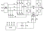
The ZVS PFC DCM that Figure 19 illustrates three-phase four switch isolation of the two winding transformers of having of the embodiment of the invention input full-bridge type output rectifier that boosts.
Figure 20 illustrates four controlled ripple doors of the phase shift of switch during switching cycle according to circuit among Figure 19 of the embodiment of the invention.
Figure 21 illustrates the PWM ripple door of four switches during switching cycle of circuit among Figure 19 of the embodiment of the invention.
Figure 22 illustrate according to the embodiment of the invention with Figure 19 in the block diagram of controller of which couple.
Figure 23 illustrates ZVS PFC DCM according to three-phase four switch isolation of single winding transformer of having of the embodiment of the invention input full-bridge type output rectifier that boosts.
Figure 24 illustrates the phase shift ripple door of four switches during switching cycle according to circuit among Figure 23 of the embodiment of the invention.
Figure 25 illustrates the PWM ripple door of four switches during switching cycle according to circuit among Figure 23 of the embodiment of the invention.
Figure 26 illustrate according to the embodiment of the invention with Figure 23 in the block diagram of controller of which couple.
Figure 27 illustrates ZVS PFC DCM according to three-phase four switch isolation of two winding transformers of having of the embodiment of the invention and the DC electric current isolating capacitor input full-bridge type output rectifier that boosts.
Figure 28 illustrates ZVS PFC DCM according to three-phase four switch isolation of single winding transformer of having of the embodiment of the invention and the DC electric current isolating capacitor input full-bridge type output rectifier that boosts.
Figure 29 illustrates ZVS PFC DCM according to three-phase four switch isolation with two transformers and two output inductor devices of the embodiment of the invention input forward output rectifier that boosts.
Figure 30 illustrates the PWM ripple door of four switches during switching cycle according to circuit among Figure 29 of the embodiment of the invention.
Figure 31 illustrates ZVS PFC DCM according to three-phase four switch isolation with two transformers and output inductor device of the embodiment of the invention input forward output rectifier that boosts.
Figure 32 illustrates ZVS PFC DCM according to three-phase four switch isolation with two transformers and output inductor device of the embodiment of the invention input flyback output rectifier that boosts.
Figure 33 illustrates the PWM ripple door of four switches during switching cycle according to circuit among Figure 32 of the embodiment of the invention.
Figure 34 illustrates the staggered three-phase two switch ZVS PFC DCM boost rectifiers according to the embodiment of the invention.
Figure 35 illustrates the staggered three-phase two switch ZVS PFC DCM boost rectifiers with DC electric current isolating capacitor according to the embodiment of the invention.
Figure 36 illustrates the ZVS PFC DCM boost rectifier according to staggered three-phase two switch isolation of the embodiment of the invention.
Figure 37 illustrates the ZVS PFC DCM boost rectifier according to staggered three-phase two switch isolation with DC electric current isolating capacitor of the embodiment of the invention.
Figure 38 illustrates the ZVS PFC DCM boost rectifier according to staggered three-phase two switch isolation with additional phase shift control of the embodiment of the invention.
Figure 39 illustrates four controlled ripple doors of the phase shift of switch during switching cycle according to circuit among Figure 38 of the embodiment of the invention.
Figure 40 illustrates the ZVS PFC DCM boost rectifier according to staggered three-phase two switch isolation with two transformers and additional phase shift control of the embodiment of the invention.
Figure 41 illustrates the ZVS PFC DCM boost rectifier according to two switch isolation of the three-phase with resonant element of the embodiment of the invention.
Figure 42 illustrates the ZVS PFC DCM boost rectifier according to four switch isolation of the three-phase with resonant element of the embodiment of the invention.
Figure 43 illustrates the two switch ZVS PFC DCM boost rectifiers of the three-phase with inductive coupling heater coil and two resonant capacitors according to the embodiment of the invention.
Figure 44 illustrates the two switch ZVS PFC DCM boost rectifiers of the three-phase with load coil and two resonant capacitors according to the embodiment of the invention.
Figure 45 illustrates the four switch ZVS PFC DCM boost rectifiers of the three-phase with load coil and resonant capacitor according to the embodiment of the invention.
Figure 46 illustrates the three-phase two switch ZVS PFC DCM boost rectifiers according to a plurality of load coils of having of the embodiment of the invention and selector switch.
Embodiment
The present invention relates to the three-phase rectifier embodiment, this scheme provides the low THD of input current and the switch soft handover in high PF and the wide loading range.The embodiment of non-isolation and the embodiment of isolation are described below.The embodiment of non-isolation can reduce common-mode noise and the autobalance of split capacitor device is provided when the following line transformer that employing is connected in series.The embodiment of isolating can provide isolates output and input side electricity.And, adopting additional phase shift or pulse width modulation (PWM) control by the switch that utilize to increase, the embodiment of isolation can strict their output voltage of control, so that unnecessary mains ripple minimizes.Also can be with staggered electric current and the mains ripple of circuit to reduce them.
Fig. 6 illustrates the block diagram according to the low Harmonics of Input boost rectifier of three-phase two switch ZVS PFC DCM of the embodiment of the invention.The input of this circuit is by three boost inductor L by electromagnetic interface filter and the coupling of three-phase input end
1, L
2And L
3And three capacitor C that dispose connection with Y shape (" star ")
1, C
2And C
3Form.The common point N of filtering capacitor is connected to switch S
1And S
2Between mid point and be connected to division output capacitor C
O1And C
O2Mid point.Be used for capacitor C that inductor current is resetted
RBe connected the two ends of the switch that is connected in series, and by coupling inductor L
CWith the output uncoupling.
Rectifier comprises: input stage, this input stage are used to receive the three-phase input voltage relevant with neutral node; And output stage, this output stage is used for and at least one load coupling.This output stage comprises a plurality of output capacitor C with neutral node N coupling
O1And C
O2
Rectifier further comprises the one or more capacitor C between the corresponding and neutral node N that is coupling in three-phase input voltage
1, C
2And C
3, and comprising one or more switching conversion stages, each switches conversion stage and has a plurality of switch S that are coupled with neutral node N
1And S
2Each switch can be mos field effect transistor (MOSFET) or the insulated gate transistor (IGBT) with inverse parallel diode.
Fig. 6 illustrates the switch S that comprises with the neutral node coupling
1And S
2One switch conversion stage.Switch S
1And S
2With the fixed duty cycle operation of 50% duty ratio basically.These one or more conversion stages further comprise the corresponding one or more boost inductor L that are coupled with three-phase input voltage
1, L
2And L
3, be coupling in the one or more input bridge diode D between described a plurality of switches of these one or more boost inductors and conversion stage
1-D
6, and one or more striding capacitance device C of being coupling in described a plurality of switch ends of conversion stage
R
Rectifier further comprises one or more controllers, and it is used for changing the switching frequency of described a plurality of switches based on the state of at least one load and input voltage at least one; And comprise one or more decoupling levels, each decoupling level comprises one or more inductance elements, for example inductor L
COr transformer, these one or more inductance elements are used for output stage and one or more switching conversion stages at least one carried out the inductance uncoupling.
Each output capacitor can be used for being coupling at least one load two ends, and the voltage at each output capacitor two ends can essence equate.
Rectifier provides the low THD of input current and the switch soft handover in high PF and the wide loading range.This is by realizing with DCM operation boost inductor and by the output voltage of controlling rectifier with variable frequency.In addition, when the following line transformer that employing is connected in series, rectifier shows the common-mode noise of reduction and has the autobalance of split capacitor device.
When rectifier comprises a plurality of switching conversion stages and each switches corresponding in conversion stage and the described one or more decoupling levels one when being coupled, controller can be further used for to interlock or parallel way is operated a plurality of switches of described a plurality of switching conversion stages.These one or more switching conversion stages can by one or more isolating capacitors come with one or more decoupling levels in corresponding decoupling grade coupled.
The capacitor C that Y shape connects
1, C
2And C
3Main purpose be to create virtual ground, that is, have the node of the electromotive force identical with importing (source) voltage neutral point, this input (source) voltage neutral point is physically disabled in three-way electric power system.By dummy neutral N is directly connected to switch S
1And S
2Between mid point, realize the uncoupling of three input currents.In such uncoupling circuit, the electric current in each of three inductors only depends on corresponding phase voltage, and this reduces THD and increases PF.
Particularly, in the circuit of Fig. 6, bridge diode D
1-D
6In switch S
1Only allow positive input voltage to pass through switch S during connection
1Transmit electric current, and in switch S
2Only allow negative input voltage to pass through switch S during connection
2Transmit electric current.Can when being zero, switch ends voltage essence connect switch.Therefore, work as switch S
1During connection, have the positive voltage half line road cycle (half-line cycle) mutually in any boost inductor carry positive current; And work as switch S
2During connection, have the negative voltage half line road cycle mutually in any boost inductor carry negative current.In switch S
1Off period, the energy of storing in being connected to the inductor of positive phase voltage is provided for capacitor C
R, and in switch S
2Off period, the energy of storing in the inductor that is connected to negative voltage is provided for capacitor C
R
Because at each switching cycle, capacitor C
RThe voltage of each terminal along with high dV/dt changes, so coupling inductor L
CBe connected striding capacitance device (flying capacitor) C
RAnd between the output, isolate will export with these quick high voltages transformations that produce unacceptable common mode EMI noise usually.Adopt coupling inductor Lc, the output common mode noise is very low, and this is because it is comprised in by S
1-S
2-C
RIn the relatively little zone that loop constitutes.And, because in output and switch S
1, S
2Between have the coupling inductor Lc that impedance is provided, therefore parallel connection/the functional interleaving of a plurality of rectifiers is possible.
Fig. 7 illustrates the simplified model according to circuit among Fig. 6 of the embodiment of the invention, and this model shows the reference direction of electric current and voltage.For the analysis that simplifies the operation, suppose that the pulsating voltage of the input and output filtering capacitor shown in Fig. 6 is insignificant, make it possible to by constant pressure source V
AN, V
BN, V
CN, V
O1And V
O2The voltage at expression input and output filtering capacitor two ends.Equally, suppose that when being in on-state, semiconductor shows zero resistance, that is, and their short circuits.Yet, in this analysis, do not ignore the output capacitance of switch.
With the coupling inductor L among Fig. 6
CBe modeled as and have magnetizing inductance L
MWith leakage inductance L
LK1, L
LK2The double winding ideal transformer.At last, because capacitor C
RThe average voltage at two ends and output voltage V
O(V
O=V
O1+ V
O2) equate, therefore with capacitor C
RBe modeled as constant pressure source.The circuit diagram of simplifying rectifier is shown in Figure 7.Work as V
AN>0, V
BN<0 and V
CN<0 o'clock, the 60 degree sectors in the electric current among Fig. 7 and the reference direction of voltage and line cycle were corresponding.
In order further to be beneficial to interpreter operation, Fig. 8 a-8j illustrates according to the topology-level of circuit during switching cycle among Fig. 7 of the embodiment of the invention, and Fig. 9 illustrates the power stage keying waveform according to the embodiment of the invention.
As can be from switch S in Fig. 9
1And S
2Door drive that sequential chart sees like that, in the circuit in Fig. 6, switch S
1And S
2With the complimentary fashion operation, between switch of disconnection and another switch of disconnection, has short dead time (dead time).Utilize this gating strategy, these two switches can both be realized ZVS.Yet in order to keep ZVS at the input voltage that changes and/or output loading, rectifier adopts changeable switch frequency control.
Determine minimum frequency by full load and minimum input voltage, and determine peak frequency by underload and maximum input voltage.In case of necessity, rectifier can be with controlled burst mode or the operation of pulse skip mode, to avoid unnecessary high-frequency operation under non-loaded or utmost point light load condition.It should be noted that and to adopt other control strategy to this circuit, comprise constant frequency PWM control.Yet,, can not keep ZVS at PWM control.
As shown in Fig. 8 (a) and Fig. 9, in switch S
1In t=T
1Before the place disconnects, inductor current i
L1Flow through switch S
1Inductor current i
L1 slope and V
AN/ L
1Equate, and at t=T
1The peak value of place's inductor current is approximately:
Wherein, V
ANBe that voltage and Ts are switching cycles between circuit and neutral point.Because at cut-off switch S
1With the connection switch S
2Between dead time very short than switching cycle Ts, therefore in formula (1), ignored the effect of dead time.At T
0And T
1Between time period during, current i
O1With-V
O1/ (L
M+ L
LK1) speed reduce and current i
O2With (V
CR-V
O1)/(L
M+ L
LK2) speed increase.Magnetizing current i
MIt is current i
O1And i
O2Between difference.
It should be noted that coupling inductor L
MThe magnetizing inductance value be designed to enough greatly, make the pulsating current materially affect rectifier operation not of coupling inductor.As shown in Figure 6, inductor L
CTwo windings be coupled in the mode of offsetting from the magnetic flux of the difference current of these two windings, make it possible under the unsaturation situation, obtain big magnetizing inductance by the little gap in the magnetic core.Although in the topology-level in Fig. 8 current i has been shown
O1And i
O2, but because this current i
O1And i
O2Effect be insignificant, therefore they are not discussed further.
At t=T
1The place works as switch S
1During disconnection, inductor current i
L1Begin switch S
1Output capacitance charge, as shown in Fig. 8 (b).Because switch S
1And switch S
2The summation of the voltage at two ends by clamp to " flying to stride " condenser voltage V
CR, so switch S
2The discharge rate and the switch S of output capacitance
1The charge rate of output capacitance identical.This time period is in switch S
2Output capacitance finish and switch S when discharging fully
2The inverse parallel body diode at t=T
2The place begins conduction, as shown in Fig. 8 (c) and Fig. 9.
Because switch S
2Body diode by forward bias, so inductor current i
L2And i
L3Beginning is linear to increase.At t=T
3The place connects switch S with ZVS
2And inductor current i
L2And i
L3From switch S
2Inverse parallel diode rectification commutation to this switch, as shown in Fig. 8 (d).This time period is at inductor current i
L1In t=T
4When being reduced to zero, the place finishes.In order to keep the DCM operation, at t=T
3And t=T
4Between time period less than switching cycle T
SHalf, this means inductor current i
L1The rate of rise should be less than its descending slope.As a result, with output voltage V
O" flying to stride " the capacitor C that equates
RThe minimum voltage V at two ends
CR (MIN)Be:
Wherein, V
AN-PKBe voltage between peak value circuit and neutral point.
It shall yet further be noted that because at T
2-T
4Interim inductor current i
L2And i
L3With with inductor current i
L1Opposite direction flows, and therefore passes through switch S
2Average current reduce, thereby the switch in the rectifier that is proposed shows the power loss that reduces.
At t=T
4And t=T
5Between time period during, inductor current i
L2And i
L3Continue to flow through switch S
2, as shown in Fig. 8 (e).As shown in Figure 9, inductor current i
L2And i
L3Slope during this time period equals V respectively
BN/ L
2And V
CN/ L
3In switch S
2In t=T
5In the moment that the place disconnects, the peak value of inductor current is approximately:
As from formula (1), (3) and (4) as can be seen, the input voltage that the peak value of each inductor current is corresponding with it is proportional.
In switch S
2In t=T
5After the place disconnects, inductor current i
L2And i
L3Beginning is simultaneously to switch S
2Output capacitance charging and to switch S
1Output capacitance discharge, as shown in Fig. 8 (f).This time period is at t=T
6The place finishes, at this moment switch S
1Output capacitance discharged fully and its inverse parallel diode begin the conduction, as shown in Fig. 8 (g) and Fig. 9.At t=T
6Afterwards, switch S
1Can connect with ZVS.In Fig. 9, switch S
1At t=T
7The place connects.As shown in Fig. 8 (h), in case switch S
1Connect, constantly the inductor current i that increases
L1Just with inductor current i
L2And i
L3Opposite direction flows through switch S
1, make switch S
1Only carry current i
L1With current i
L2, i
L3The difference of sum.This time period is at t=T
8The place finishes, at this moment inductor current i
L3Reduce to 0.At T
8-T
9During time period, ever-reduced inductor current i
L2Continue to flow through switch S
1, as shown in Fig. 8 (i).At last, at inductor current i
L2At t=T
9The place reaches at 0 o'clock, begins new switching cycle, as shown in Fig. 8 (j).
In the circuit shown in Fig. 6, because each boost inductor is proportional in the charging current of the time durations of the related switch connection phase voltage corresponding with it, and the discharging current of each boost inductor and " flying to stride " condenser voltage V
CRProportional with the difference of the phase voltage of correspondence, as shown in the inductor current waveform among Fig. 9, so the average inductor current<I of each boost inductor during switching cycle
L (AVG)>
TsBe:
Wherein, L=L
1=L
2=L
3, and ω is the angular frequency of line voltage distribution.
Conversion than M is to output voltage by the definition input:
And recall striding capacitance device C
RThe voltage at two ends and output voltage V
OEquate, i.e. V
CR=V
O, the average inductor current<I in the formula (5) then
L (AVG)>
TsCan be written as again:
It should be noted that average inductor current I in the formula (7)
L (AVG)Expression formula identical with expression formula with the average inductor current of the single-phase constant frequency voltage lifting PFC of DCM operation.The current distortion of the average inductor current in the formula (7) is caused by denominator term (M-sin ω t), and this current distortion depends on voltage conversion ratio M.
In Table I, summed up harmonic content for the average inductor current of different M.As finding out from Table I, 3 order harmonicses are main distortion components.Yet, in three-way electric power system, because the neutral line unavailable (perhaps not connecting), thereby line current can not comprise three times of subharmonic (odd-multiple of 3 order harmonicses and 3 order harmonicses).As a result, because according to Table I, remaining harmonic wave is only contributed less than 1% of whole current distortion, therefore the circuit that is proposed shows low-down THD and high PF.It should be noted that line current can not comprise the 3rd order harmonics, filtering capacitor C
1-C
3Voltage will comprise this 3 order harmonics and automatically get rid of 3 order harmonicses of inductor current.
This circuit can be realized with many other embodiment.For example, Figure 10 is the embodiment with two independent loads according to the embodiment of the invention.Because therefore the voltage at two the output capacitor two ends of biswitch rectifier autobalance that proposed do not need other voltage balancing circuit.Because inductor L
CThe average voltage at winding two ends be zero, therefore since in Figure 10 circuit switch S
1And S
2The average voltage at two ends respectively with capacitor C
1And C
2The voltage V at two ends
O1And V
O2Equate, so realized the natural balance of voltage.Because switch is with approximate 50% duty ratio operation, so their average voltage and V
CR/ 2 equate, make V
O1=V
O2=V
CR/ 2.
Can also be according to the embodiment of the invention, the embodiment among Fig. 6 is embodied as have as shown in Figure 11 two independently inductors, and has as shown in Figure 12 isolating capacitor C according to the embodiment of the invention
BThis isolating capacitor is coupling between neutral node and the output capacitor.By increasing isolating capacitor C as shown in Figure 12
B, can prevent from switch S
1With S
2Between node be circulated to capacitor C
O1With C
O2Between any DC electric current of node.
Figure 13 shows according to the embodiment of the invention, when being three-phase four switching systems at capacitor C
O1With C
O2Between node can be connected to the neutral line of input source.Circuit shown in Figure 13 specifically can be used for the uninterrupted power supply of non-isolation, and (this system need be connected to the neutral line of three-phase input source for Uninterruptible Power Supply, UPS) system, so that the AC voltage output of common ground to be provided.
Figure 14 illustrates embodiment among Fig. 6 and also can be embodied as according to the embodiment of the invention and have two isolating diodes.This isolating diode can be coupling between a plurality of switches and the one or more striding capacitance device.By increasing by two extra diode D
B1And D
B2, can prevent the switch breakdown fault that overlaps and cause by the accident of gate signal.
Because embodiment of circuit is based on the booster type rectifier, therefore there is charging current in the moment of recovery again in the moment that power supply is connected to input source or after input voltage disconnects from it.
Figure 15 illustrates can increase the inrush current control circuit to prevent and/or bypass high peak electric current according to the embodiment of the invention.This inrush current control circuit can be coupling between input voltage and the capacitor.
Figure 16 illustrates embodiment among Fig. 6 and can also be implemented as according to the embodiment of the invention and have six controlled switchs rather than six input diodes.By adopting six switch S R
1-SR
6, it is possible that bidirectional energy flows, to be desired function compensate with the phase angle to the source electric current where necessary for this.
Figure 17 illustrates the embodiment according to the output with isolation of the embodiment of the invention.The primary side and the circuit shown in Figure 16 of the buffer circuit among Figure 17 are similar, except the coupling inductor L in the circuit shown in Figure 16
COutside the transformer TR replacement that is constituted by two windings and centre cap secondary winding.At the secondary side of transformer TR, rectifier D
O1And D
O2And output filter element L
OAnd C
OBe coupling between the secondary winding and output of transformer TR.
Figure 18 illustrates the embodiment with the isolating transformer TR that is made of winding of centre cap and centre cap secondary winding according to the embodiment of the invention.For high PF and the low THD that realizes this circuit, switch S
1And S
2Switching frequency and duty ratio should be near constant during the half period of line frequency.As a result, the bandwidth of the Control and Feedback that is adopted can be significantly less than line frequency, and this produces tangible output voltage pulsation at the line frequency place through rectification, wherein is six times of high-frequencies of circuit fundamental frequency through the line frequency of rectification.
Usually, most of power supplys have two series-connected stages: PFC rectification stage and secondary isolation DC-DC conversion stage.As a result, although the output voltage of a PFC rectifier comprises the line frequency mains ripple through rectification, secondary isolation DC-DC conversion stage can be regulated its output voltage by the high frequency bandwidth feedback controller of himself.For the function with this two-stage is attached in the single-stage, it is inevitable that output voltage is carried out the strictness adjusting.
Figure 19 illustrates ZVS PFC DCM according to three-phase four switch isolation of the two winding transformers of having of the embodiment of the invention input full-bridge type output rectifier that boosts, and it provides strict controlled isolation output.This rectifier comprises the output stage that is used to receive the input stage of the three-phase input voltage relevant with neutral node and is used for being coupled with at least one load.This output stage comprises a plurality of output capacitors with the neutral node coupling.
Rectifier further comprises the one or more capacitors between the mutually corresponding and neutral node that is coupling in three-phase input voltage, and comprise one or more switching conversion stages, each conversion stage has a plurality of switches with the neutral node coupling, these a plurality of switches are operated with fixed duty cycle, and this fixed duty cycle is to be essentially 50% duty ratio.These one or more conversion stages further comprise with the corresponding one or more boost inductors that are coupled of three-phase input voltage, be coupling between a plurality of switches of one or more boost inductors and conversion stage one or more input bridge diodes and at one or more striding capacitance devices of a plurality of switch ends couplings of conversion stage.
Rectifier further comprises one or more controllers, these one or more controllers are used for changing based at least one of the state of described at least one load and input voltage the switching frequency of a plurality of switches of corresponding switching conversion stage, and comprise one or more decoupling levels, each decoupling level comprises the one or more transformers that are used at least one isolation of output stage and described one or more switching conversion stages.
Rectifier further comprises a plurality of auxiliary switch S by a plurality of switch couplings of described at least one transformer and described one or more switching conversion stages
3And S
4Controller is further used for operating a plurality of auxiliary switches according in phase shift or the pulse width modulation at least one.
Described a plurality of auxiliary switch can form at least one full-bridge converter.Transformer can comprise the junction point that is coupling in auxiliary switch and a winding between the neutral node.Transformer can comprise by one or more isolating capacitors and is coupling in the one or more windings that switch between the conversion stage until neutral node.
According to embodiments of the invention, by increasing and main switch S
1And S
2Cao Zuo extra switch S together
3And S
4, as shown in the sequential chart among Figure 20 and Figure 21 like that, the embodiment of isolation also can realize the strictness control to its output voltage except high PF and low THD.Figure 20 illustrates switch S
1-S
4The ripple door.S
1And S
2Switching appear at time T
0Locate and S
3And S
4Switching appear at time T
1The place.Phase shift between two handover events forms the PWM voltage waveform V at transformer TR two ends
P, as shown in Figure 20.Although all switch S
1-S
4Operate to obtain high PH and low THD with the switching frequency of slow variation and near 50% duty ratio, control but the control method that is proposed can provide additional by the change angle of phase displacement, this angle of phase displacement can strictly be regulated output voltage.
Figure 21 illustrates the employing switch S
3And S
4Another controlling schemes of PWM gating.The example of the controlling schemes that is proposed shown in the simplified block diagram in Figure 22.Striding capacitance device C
R1The voltage at two ends is controlled by the low bandwidth FREQUENCY CONTROL and output voltage is controlled by high bandwidth phase shift or PWM control.It should be noted that striding capacitance device C
R2The voltage at two ends or output voltage can be controlled by the low bandwidth FREQUENCY CONTROL, but not are controlled by striding capacitance device C
R1The voltage at two ends.
Figure 23 illustrates according to the embodiment of the invention and also can adopt the transformer that is made of a single winding and centre cap secondary winding to implement embodiment among Figure 19.According to the embodiment of the invention, switch S
1-S
4Sequential chart and the primary voltage V of transformer TR
PShown in Figure 24 and Figure 25, represent phase shift control and PWM control respectively.Figure 26 illustrates the simplified block diagram according to the controlling schemes of the embodiment of the invention.
Figure 27 and Figure 28 illustrate according to the embodiment among embodiment of the invention Figure 19 and Figure 23 also can adopt isolating capacitor C respectively
BImplement.By increasing as Figure 27 and isolating capacitor C shown in Figure 28
B, can eliminate any DC electric current in the winding of transformer TR.Although represented to have the centre cap secondary winding of transformer and the output circuit of two output diodes at the circuit of the isolation shown in Figure 17-28, any known output rectifier for example current doubler rectifier, full bridge rectifier, semibridge system rectifier etc. with multiplication of voltage capacitor all can adopt in embodiments.And, can adopt the synchronous rectifier that self has control circuit in embodiments, rather than filtered diode.
Figure 29 illustrates the embodiment that exports according to the strict controlled staggered isolated forward type of warp of having of the embodiment of the invention.The primary side of a forward type structure is by switch S
2And S
3, transformer TR
1, diode D
R1And switch S
1Body diode form, and secondary side is by diode D
O1And D
O2And output inductor L
O1Form.The primary side of other forward type structure is by switch S
1And S
4, transformer TR
2, diode D
R2And switch S
2Body diode form and secondary side by diode D
O3And D
O4And output inductor L
O2Form.
Figure 30 illustrates the switch S according to the embodiment of the invention
1-S
4And transformer TR
1And TR
2Primary voltage V
P1And V
P2The ripple door.Connect switch S simultaneously
2And S
3Cause transformer TR
1The voltage V at winding two ends
CRIn switch S
3In time T
1After the place disconnects, transformer TR
1Magnetizing current flow through diode D
R1And switch S
1Body diode.As a result, at transformer TR
1The two ends of a winding cause negative voltage-V
CR, when its magnetizing current is resetted fully, as shown in Figure 30.By diverter switch S
1And S
4, at transformer TR
2Two ends cause similar voltage waveform, as shown in Figure 30.It should be noted that in order to obtain high PH and low TD, switch S
1And S
2Always keep duty ratio near 50%.
Figure 31 illustrates according to the embodiment among embodiment of the invention Figure 29 also can adopt single output inductor L
OAnd three output diode D
O1-D
O3Implement.
Figure 32 illustrates according to the embodiment embodiment of the invention, that have staggered flyback (flyback) the type output of isolating of the controlled warp of strictness.A flyback type structure is by switch S
2And S
3, transformer TR
1And diode D
O1Form.Other flyback type structure is by switch S
1And S
4, transformer TR
2And diode D
O2Form.
Figure 33 illustrates the switch S according to the embodiment of the invention
1-S
4And transformer TR
1And TR
2Primary voltage V
P1And V
P2The ripple door.Connect switch S simultaneously
2And S
3Cause transformer TR
1The voltage V at winding two ends
CRIn switch S
3In time T
1After the place disconnects, transformer TR
1Magnetizing current by diode D
O1Flow to output capacitor C
O
As a result, if transformer TR
1With DCM operation (as shown in Figure 30), then at transformer TR
1Winding two ends cause reflection output voltage-nV
O, when its magnetizing current reached zero, wherein n was transformer TR
1Turn ratio.If transformer TR
1Magnetizing inductance enough big, then magnetizing current becomes continuous.Pass through switch S
1And S
4Switching, at transformer TR
2Two ends cause similar voltage waveform, as shown in Figure 33.
Figure 34 illustrates can be in parallel or staggered according to the embodiment among embodiment of the invention Fig. 6.In simple parallel operation, switch S
1And S
3Drive by a gating signal, and switch S
2And S
4Drive together by other complementary strobe signals.In functional interleaving, switch S
1And S
4Driven together, and switch S
2And S
3Drive simultaneously by complementary signal.Because the coupling inductor L of uncoupling impedance is provided between output and switch
C, the parallel connection/functional interleaving in this circuit is possible.
Figure 35 illustrates according to the embodiment of the invention by increasing isolating capacitor C
B, can prevent from switch S
1-S
4Between node be circulated to output capacitor C
O1With C
O2Between any DC electric current of node.
Figure 36 illustrates can be in parallel or staggered according to the embodiment among the invention process Figure 17.In simple parallel operation, switch S
1And S
3Drive by same signal, and switch S
2And S
4Drive together with complementary signal.In interleaving mode, switch S
1And S
3Driven together, and switch S
2And S
4Drive simultaneously by complementary signal.
Figure 37 illustrates according to the embodiment of the invention by increasing isolating capacitor C
B, can prevent from switch S
1With S
2Between node be circulated to switch S
3With S
4Between any DC electric current of node.
If Figure 38 illustrates PFC rectifier according to two isolation of the embodiment of the invention and is connected in parallel then can having to obtain strict controlled output under the situation of extra switch.Rectifier comprises the output stage that is used to receive the input stage of the three-phase input voltage relevant with neutral node and is used for being coupled with at least one load.Output stage comprises a plurality of output capacitors with the neutral node coupling.
Rectifier further comprises the one or more capacitors between the mutually corresponding and neutral node that is coupling in three-phase input voltage, and comprise that at least two switch conversion stage, for example, the PFC rectifier of isolating, each conversion stage has a plurality of switches with the neutral node coupling, these a plurality of switches are operated with fixed duty cycle, and this fixed duty cycle is 50% a duty ratio basically.Switching conversion stage further comprises and the corresponding one or more boost inductors that are coupled of three-phase input voltage, one or more striding capacitance devices of being coupling in the one or more input bridge diodes between a plurality of switches of these one or more boost inductors and conversion stage and being coupled in a plurality of switch ends of conversion stage.
Rectifier further comprises one or more controllers, and these one or more controllers are used for changing the corresponding switching frequency that switches a plurality of switches of conversion stage based at least one of the state of at least one load or input voltage; And rectifier comprises one or more decoupling levels, and each decoupling level comprises the one or more transformers that are used for output stage and the isolation of a plurality of switching conversion stage.This transformer comprises the one or more windings that are coupling between a plurality of switching conversion stages.Controller is further used for controlling a plurality of switches of operating a plurality of switching conversion stages with phase shift.
Transformer can comprise by the one or more isolating capacitors that are connected to neutral node and is coupling in one or more windings between a plurality of switching conversion stages.
Figure 39 illustrates the switch S according to the embodiment of the invention
1-S
4The ripple door.The S of the one PFC level
1And S
2Switching appear at time T
0Locate and the S of the 2nd PFC level
3And S
4Switching appear at time T
1The place.This phase shift between these two handover events produces PWM voltage waveform V at two winding two ends of transformer TR
P1And V
P2, as shown in Figure 39.Switch S
1-S
4Recently operate obtaining high PF and low THD with the switching frequency of slow variation and near 50% duty, and the strict output voltage of regulating of the variation of angle of phase displacement.
Figure 40 illustrates also can adopt according to the embodiment among embodiment of the invention Figure 39 has two transformer TR that are used for the secondary winding that is connected in series that electric current shares
1And TR
2Implement.
Figure 41 illustrates the embodiment of circuit that has semibridge system mode of resonance structure and isolate output according to the embodiment of the invention, and Figure 42 illustrates the full-bridge type mode of resonance structure according to the embodiment of the invention.Any tank circuits for example series, parallel, LLC, LCC and LLCC resonant circuit etc. all can use.
The coupling inductor that Figure 43 illustrates according to the rectifier shown in embodiment of the invention Fig. 6 can be replaced by two load coils.Therefore, one or more load coils can be the inductance elements of rectifier.Resonant capacitor C
R1And C
R2And load coil forms resonant groove path, with to any electric conducting material with resistance for example metal dish magnetic energy is provided.The heating of this metal dish owing to the coupling caused eddy current loss of magnetic energy.
Figure 44 illustrates another embodiment according to the circuit with load coil and semibridge system structure of the embodiment of the invention, and Figure 45 illustrates the circuit with load coil and full-bridge type structure according to the embodiment of the invention.Figure 46 illustrates can be by the switch that is connected in series and which couple according to a plurality of load coils of the embodiment of the invention.The switch that is connected in series can be corresponding coil selector switch.
Table I
The THD of the average boost inductor electric current when three times of subharmonic paths are provided, when the neutral line of three-phase input source directly is connected with dummy neutral N and harmonic wave (M be definition in formula (6) input to the output voltage conversion than).

Claims (53)
1. one kind low Harmonics of Input three-phase voltage increasing rectifier comprises:
Input stage is used to receive the three-phase input voltage relevant with neutral node;
Output stage is used for and at least one load coupling, and described output stage comprises a plurality of output capacitors with described neutral node coupling;
Be coupling in the correspondence of described three-phase input voltage and the one or more capacitors between the described neutral node;
One or more switching conversion stages, each switches conversion stage and has a plurality of switches that are coupled with described neutral node, described a plurality of switch is operated with fixed duty cycle, described fixed duty cycle is to be essentially 50% duty ratio, and described one or more conversion stages further comprise the corresponding one or more boost inductors that are coupled with described three-phase input voltage, be coupling in the one or more input bridge diodes between described a plurality of switches of described one or more boost inductor and described conversion stage, and the one or more striding capacitance devices that are coupling in described a plurality of switch ends of described conversion stage;
One or more controllers, at least one that is used for based on the state of described at least one load or input voltage changes the switching frequency of described a plurality of switches; And
One or more decoupling levels, each decoupling level comprise the one or more inductance elements that are used at least one induction uncoupling of described output stage and described one or more switching conversion stages.
2. low Harmonics of Input boost rectifier according to claim 1, wherein, one or more switches of described a plurality of switches are connected when the voltage of described one or more switch ends is zero substantially.
3. low Harmonics of Input boost rectifier according to claim 1, wherein, described controller be used for the peak frequency determined based on the minimum frequency of determining by full load and minimum input voltage or by underload and maximum input voltage these two at least one and change switching frequency.
4. low Harmonics of Input boost rectifier according to claim 1, wherein, described controller be used for underload and non-loaded between scope in burst mode operation.
5. low Harmonics of Input boost rectifier according to claim 1, wherein, the coupling that is magnetized of described inductance element.
6. low Harmonics of Input boost rectifier according to claim 1, wherein, each in the described output capacitor all is used to be coupling at least one load two ends.
7. low Harmonics of Input boost rectifier according to claim 1, wherein, the voltage at the two ends of each in the described output capacitor is equal substantially.
8. low Harmonics of Input boost rectifier according to claim 1 further comprises the isolating capacitor between the output capacitor that is coupling in described neutral node and described output stage.
9. low Harmonics of Input boost rectifier according to claim 1, wherein, the coupling of the input neutral line of the output capacitor of described output stage and three-phase and four-line input system.
10. low Harmonics of Input boost rectifier according to claim 1, wherein, the one or more isolating diodes of coupling between described a plurality of switches and described one or more striding capacitance device.
11. low Harmonics of Input boost rectifier according to claim 1, wherein, the one or more inrush current control circuits of coupling between described input voltage and described capacitor.
12. low Harmonics of Input boost rectifier according to claim 1, wherein, described input stage further comprises input electromagnetic interference electromagnetic interface filter.
13. low Harmonics of Input boost rectifier according to claim 1, wherein, described input bridge diode is a synchronous rectifier.
14. low Harmonics of Input boost rectifier according to claim 1, wherein, each switch comprises mos field effect transistor MOSFET or the insulated gate bipolar transistor IGBT with inverse parallel diode.
15. low Harmonics of Input boost rectifier according to claim 1, wherein, described one or more switching conversion stage comprises a plurality of switching conversion stages, each switches a corresponding coupling in conversion stage and the described one or more decoupling levels, and wherein, described controller is further used for operating with staggered or parallel way described a plurality of switches of described a plurality of switching conversion stages.
16. low Harmonics of Input boost rectifier according to claim 1, wherein, described one or more switching conversion stage comprises a plurality of switching conversion stages, each switches conversion stage by a corresponding coupling in one or more isolating capacitors and the described one or more decoupling levels, and wherein, described controller is further used for operating with staggered or parallel way described a plurality of switches of described a plurality of switching conversion stages.
17. low Harmonics of Input boost rectifier according to claim 1, wherein, described inductance element comprises one or more load coils.
18. low Harmonics of Input boost rectifier according to claim 17, wherein, described load coil and corresponding coil selector switch coupling.
19. one kind low Harmonics of Input three-phase voltage increasing rectifier comprises:
Input stage is used to receive the three-phase input voltage relevant with neutral node;
Output stage is used for and at least one load coupling;
Be coupling in the correspondence of described three-phase input voltage and the one or more capacitors between the described neutral node;
At least two switch conversion stage, each switches conversion stage and has a plurality of switches that are coupled with described neutral node, described a plurality of switch is operated with fixed duty cycle, described fixed duty cycle is 50% a duty ratio basically, and described switching conversion stage further comprises the corresponding one or more boost inductors that are coupled with described three-phase input voltage, be coupling in the one or more input bridge diodes between described a plurality of switches of described one or more boost inductor and described conversion stage, and the one or more striding capacitance devices that are coupling in described a plurality of switch ends of conversion stage;
One or more controllers are used for changing based at least one of the state of described at least one load or described input voltage the switching frequency of a plurality of switches of the switching conversion stage of described correspondence; And
One or more decoupling levels, each decoupling level comprises the one or more transformers that are used for described output stage and described a plurality of switching conversion stage isolation, wherein, described transformer comprises the one or more windings that are coupling between described a plurality of switching conversion stage, and wherein, described controller is further used for controlling described a plurality of switches of operating described a plurality of switching conversion stages with phase shift.
20. low Harmonics of Input boost rectifier according to claim 19, wherein, described transformer further comprises by one or more isolating capacitors and is coupling in one or more windings between a plurality of switching conversion stages.
21. low Harmonics of Input boost rectifier according to claim 19 further is included in the rectifier and the centre cap winding of the secondary side of described transformer.
22. low Harmonics of Input boost rectifier according to claim 19 further is included in the full-wave rectifier of the secondary side of described transformer.
23. low Harmonics of Input boost rectifier according to claim 19 further is included in the current doubler rectifier of the secondary side of described transformer.
24. low Harmonics of Input boost rectifier according to claim 19 further is included in the synchronous rectifier of the secondary side of described transformer.
25. low Harmonics of Input boost rectifier according to claim 19 further is included in the filter of the secondary side of described transformer.
26. low Harmonics of Input boost rectifier according to claim 19, wherein, the one or more switches in described a plurality of switches are connected when the voltage of described one or more switch ends is zero substantially.
27. low Harmonics of Input boost rectifier according to claim 19, wherein, described controller is used for these two at least one of the peak frequency determined based on the minimum frequency of being determined by full load and minimum input voltage or by underload and maximum input voltage and changes switching frequency.
28. low Harmonics of Input boost rectifier according to claim 19, wherein, described controller be used for underload and non-loaded between scope in burst mode operation.
29. low Harmonics of Input boost rectifier according to claim 19, wherein, the one or more inrush current control circuits of coupling between described input voltage and described capacitor.
30. low Harmonics of Input boost rectifier according to claim 19, wherein, described input stage further comprises input electromagnetic interference electromagnetic interface filter.
31. low Harmonics of Input boost rectifier according to claim 19, wherein, described input bridge diode is a synchronous rectifier.
32. low Harmonics of Input boost rectifier according to claim 19, wherein, each switch comprises MOSFET or the IGBT with inverse parallel diode.
33. one kind low Harmonics of Input three-phase voltage increasing rectifier comprises:
Input stage is used to receive the three-phase input voltage relevant with neutral node;
Output stage is used for and at least one load coupling;
Be coupling in the correspondence of described three-phase input voltage and the one or more capacitors between the described neutral node;
One or more switching conversion stages, each switches conversion stage and has a plurality of switches that are coupled with described neutral node, described a plurality of switch is operated with fixed duty cycle, described fixed duty cycle is to be essentially 50% duty ratio, and described one or more conversion stages further comprise the corresponding one or more boost inductors that are coupled with described three-phase input voltage, be coupling in the one or more input bridge diodes between described a plurality of switches of described one or more boost inductor and described conversion stage, and at one or more striding capacitance devices of the described a plurality of switch ends coupling of described conversion stage;
One or more controllers, at least one that is used for based on the state of described at least one load or described input stage changes the switching frequency of described a plurality of switches;
One or more decoupling levels, each decoupling level comprises the one or more transformers that are used at least one isolation of described output stage and described one or more switching conversion stages; And
A plurality of auxiliary switches of the described a plurality of switches coupling by described at least one transformer and described one or more switching conversion stages, wherein, described controller is further used for operating described a plurality of auxiliary switch according in phase shift or the pulse width modulation at least one.
34. low Harmonics of Input boost rectifier according to claim 33, wherein, described a plurality of auxiliary switches of the described a plurality of switches coupling by described at least one transformer and described one or more switching conversion stages form at least one full-bridge converter.
35. low Harmonics of Input boost rectifier according to claim 33, wherein, described transformer comprises the junction point that is coupling in described auxiliary switch and a winding between the described neutral node.
36. low Harmonics of Input boost rectifier according to claim 33, wherein, described transformer comprises a winding that is coupled to described neutral node by one or more isolating capacitors.
37. low Harmonics of Input boost rectifier according to claim 33 further is included in the rectifier and the centre cap winding of the secondary side of described transformer.
38. low Harmonics of Input boost rectifier according to claim 33 further is included in the full-wave rectifier of the secondary side of described transformer.
39. low Harmonics of Input boost rectifier according to claim 33 further is included in the current doubler rectifier of the secondary side of described transformation.
40. low Harmonics of Input boost rectifier according to claim 33 further is included in the synchronous rectifier of the secondary side of described transformer.
41. low Harmonics of Input boost rectifier according to claim 33 further is included in one or more filters of the secondary side of described transformer.
42. low Harmonics of Input boost rectifier according to claim 33, wherein, described a plurality of switches and described transformer form forward converter.
43. low Harmonics of Input boost rectifier according to claim 33 further is included in the output filter with one or more output inductors of the secondary side of described transformer.
44. low Harmonics of Input boost rectifier according to claim 33, wherein, described a plurality of switches and described transformer form flyback converter.
45. low Harmonics of Input boost rectifier according to claim 33, wherein, described transformer comprises a winding with at least one resonant inductor and the coupling of one or more resonant capacitor.
46. according to the described low Harmonics of Input boost rectifier of claim 45, wherein, described a plurality of switches and described transformer form controlled resonant converter.
47. low Harmonics of Input boost rectifier according to claim 33, wherein, one or more switches of described a plurality of switches are connected when the voltage of described one or more switch ends is zero substantially.
48. low Harmonics of Input boost rectifier according to claim 33, wherein, described controller is used for these two at least one of the peak frequency determined based on the minimum frequency of being determined by full load and minimum input voltage or by underload and maximum input voltage and changes switching frequency.
49. low Harmonics of Input boost rectifier according to claim 33, wherein, described controller be used for underload and non-loaded between scope in burst mode operation.
50. low Harmonics of Input boost rectifier according to claim 33, wherein, the one or more inrush current control circuits of coupling between described input voltage and described capacitor.
51. low Harmonics of Input boost rectifier according to claim 33, wherein, described input stage further comprises input electromagnetic interference electromagnetic interface filter.
52. low Harmonics of Input boost rectifier according to claim 33, wherein, described input bridge diode is a synchronous rectifier.
53. low Harmonics of Input boost rectifier according to claim 33, wherein, each switch comprises MOSFET or the IGBT with inverse parallel diode.
Priority Applications (1)
| Application Number | Priority Date | Filing Date | Title |
|---|---|---|---|
| CN201910593180.1A CN110289777B (en) | 2012-01-31 | 2012-05-02 | Three-phase soft switching PFC rectifier |
Applications Claiming Priority (2)
| Application Number | Priority Date | Filing Date | Title |
|---|---|---|---|
| US13/362,620 US8687388B2 (en) | 2012-01-31 | 2012-01-31 | Three-phase soft-switched PFC rectifiers |
| US13/362,620 | 2012-01-31 |
Related Child Applications (1)
| Application Number | Title | Priority Date | Filing Date |
|---|---|---|---|
| CN201910593180.1A Division CN110289777B (en) | 2012-01-31 | 2012-05-02 | Three-phase soft switching PFC rectifier |
Publications (1)
| Publication Number | Publication Date |
|---|---|
| CN103227575A true CN103227575A (en) | 2013-07-31 |
Family
ID=48783803
Family Applications (2)
| Application Number | Title | Priority Date | Filing Date |
|---|---|---|---|
| CN201910593180.1A Active CN110289777B (en) | 2012-01-31 | 2012-05-02 | Three-phase soft switching PFC rectifier |
| CN2012101314312A Pending CN103227575A (en) | 2012-01-31 | 2012-05-02 | Three-phase soft-switched PCF rectifiers |
Family Applications Before (1)
| Application Number | Title | Priority Date | Filing Date |
|---|---|---|---|
| CN201910593180.1A Active CN110289777B (en) | 2012-01-31 | 2012-05-02 | Three-phase soft switching PFC rectifier |
Country Status (5)
| Country | Link |
|---|---|
| US (1) | US8687388B2 (en) |
| JP (1) | JP6367520B2 (en) |
| CN (2) | CN110289777B (en) |
| DE (1) | DE102012207177B4 (en) |
| TW (1) | TWI547076B (en) |
Cited By (20)
| Publication number | Priority date | Publication date | Assignee | Title |
|---|---|---|---|---|
| CN103516211A (en) * | 2013-08-28 | 2014-01-15 | 浙江工业大学 | LED array interface circuit containing three-winding coupled inductors |
| CN104811061A (en) * | 2015-04-30 | 2015-07-29 | 安徽动力源科技有限公司 | Novel three-phase PFC (power factor correction) rectifier |
| CN105047385A (en) * | 2015-08-17 | 2015-11-11 | 江苏科谷电子有限公司 | High-frequency transformer and electronic magnetic interference (EMI) suppression circuit including same |
| CN106385171A (en) * | 2016-09-30 | 2017-02-08 | 深圳市奥耐电气技术有限公司 | Interleaved parallel three-phase PFC circuit |
| CN106411162A (en) * | 2016-09-30 | 2017-02-15 | 深圳市奥耐电气技术有限公司 | Three-phase AC-DC (Alternating current-Direct Current) power supply changeover system |
| CN107465341A (en) * | 2017-09-08 | 2017-12-12 | 西南交通大学 | A kind of control method and control circuit of DCMBoost power factor correcting converters |
| WO2018060632A1 (en) | 2016-09-29 | 2018-04-05 | Renault Sas | Method for determining a current setpoint for a motor vehicle battery charger |
| CN108347184A (en) * | 2018-01-30 | 2018-07-31 | 安徽省金屹电源科技有限公司 | A kind of pulverized coal boiler ignition plasma cabinet power source special |
| CN108649818A (en) * | 2018-04-19 | 2018-10-12 | 东南大学 | Three-phase step-down type rectifier and its control method |
| WO2019075837A1 (en) * | 2017-10-16 | 2019-04-25 | 深圳市保益新能电气有限公司 | Single-stage isolated three-phase pfc converter and control method therefor |
| CN109995229A (en) * | 2018-01-02 | 2019-07-09 | 台达电子企业管理(上海)有限公司 | Pfc circuit |
| WO2019238404A1 (en) | 2018-06-15 | 2019-12-19 | Renault S.A.S | Method for controlling a vienna rectifier |
| CN110784109A (en) * | 2018-07-26 | 2020-02-11 | 英飞凌科技奥地利有限公司 | Power converter with low drain voltage overshoot in discontinuous conduction mode |
| CN111934568A (en) * | 2020-04-16 | 2020-11-13 | 山西大学 | Bridgeless double-Boost power factor correction rectifier capable of alternately assisting current conversion up and down |
| CN111934567A (en) * | 2020-04-16 | 2020-11-13 | 山西大学 | Bridgeless double-Boost power factor correction rectifier for left-right alternate auxiliary commutation |
| CN112104212A (en) * | 2020-09-15 | 2020-12-18 | 哈尔滨工程大学 | Three-phase two-switch rectifier filter inductor and hysteresis loop control switching frequency design method |
| CN112292797A (en) * | 2018-06-28 | 2021-01-29 | 纬湃科技有限责任公司 | Vehicle side charging circuit |
| WO2021179502A1 (en) * | 2020-03-12 | 2021-09-16 | 深圳威迈斯新能源股份有限公司 | Single-phase and three-phase compatible conversion circuit and vehicle-mounted charger |
| CN113841328A (en) * | 2019-05-21 | 2021-12-24 | 华为数字能源技术有限公司 | Boost converter and control method |
| CN114600329A (en) * | 2019-10-25 | 2022-06-07 | 日立能源瑞士股份公司 | Method and apparatus for controlled switching of coupled loads |
Families Citing this family (72)
| Publication number | Priority date | Publication date | Assignee | Title |
|---|---|---|---|---|
| US7548441B2 (en) * | 2004-02-24 | 2009-06-16 | Vlt, Inc. | Universal AC adapter |
| CA2764504C (en) | 2009-06-15 | 2016-08-23 | David Trainer | Dc voltage source converter |
| CA2768750C (en) | 2009-07-31 | 2017-01-31 | Areva T&D Uk Limited | Configurable hybrid converter circuit |
| WO2011098117A1 (en) | 2010-02-09 | 2011-08-18 | Areva T&D Uk Limited | Converter for high voltage dc dc transmission |
| US9130458B2 (en) | 2010-03-15 | 2015-09-08 | Alstom Technology Ltd. | Static VAR compensator with multilevel converter |
| KR101719393B1 (en) | 2010-04-15 | 2017-03-23 | 제네럴 일렉트릭 테크놀러지 게엠베하 | Hybrid 2-level and multilevel hvdc converter |
| CA2802933C (en) | 2010-06-18 | 2018-01-02 | Alstom Technology Ltd | Converter for hvdc transmission and reactive power compensation |
| CN103141018B (en) * | 2010-07-30 | 2015-12-16 | 阿尔斯通技术有限公司 | Comprise the HVDC converter of the full bridge unit for the treatment of the short circuit of DC side |
| KR20130100285A (en) | 2010-08-24 | 2013-09-10 | 알스톰 테크놀러지 리미티드 | Hvdc converter with neutral-point connected zero-sequence dump resistor |
| KR20130132451A (en) * | 2010-10-27 | 2013-12-04 | 알스톰 테크놀러지 리미티드 | Modular multilevel converter |
| US8891262B2 (en) * | 2011-03-24 | 2014-11-18 | Polar Semiconductor, Llc | Series switch bridgeless power supply |
| EP2719062B1 (en) | 2011-06-08 | 2018-02-28 | General Electric Technology GmbH | High voltage dc/dc converter with cascaded resonant tanks |
| CN103891121B (en) | 2011-08-01 | 2016-11-23 | 阿尔斯通技术有限公司 | DC-to-DC converter assembly |
| US9209693B2 (en) | 2011-11-07 | 2015-12-08 | Alstom Technology Ltd | Control circuit for DC network to maintain zero net change in energy level |
| US9088222B2 (en) * | 2011-11-17 | 2015-07-21 | Qualcomm Incorporated | Systems, methods, and apparatus for a high power factor single phase rectifier |
| EP2781015B1 (en) | 2011-11-17 | 2016-11-02 | General Electric Technology GmbH | Hybrid ac/dc converter for hvdc applications |
| US8891261B2 (en) * | 2012-01-31 | 2014-11-18 | Delta Electronics, Inc. | Three-phase three-level soft-switched PFC rectifiers |
| WO2013127461A1 (en) | 2012-03-01 | 2013-09-06 | Alstom Technology Ltd | Control circuit |
| DE102012005622B4 (en) * | 2012-03-22 | 2022-03-10 | Sew-Eurodrive Gmbh & Co Kg | circuit arrangement |
| CN103825474B (en) * | 2012-11-16 | 2016-08-31 | 台达电子工业股份有限公司 | The electric power conversion apparatus of low common-mode noise and application system thereof |
| KR101472457B1 (en) | 2013-08-27 | 2014-12-12 | 전자부품연구원 | Apparatus and method for power factor correlation control |
| US9647533B2 (en) * | 2013-11-08 | 2017-05-09 | One More Time Llc | PFC circuits with very low THD |
| KR101578136B1 (en) * | 2013-12-06 | 2015-12-16 | 국민대학교산학협력단 | Synchronous rectifier circuit of three-phase step down resonant type |
| KR101563900B1 (en) | 2013-12-06 | 2015-10-28 | 국민대학교산학협력단 | Synchronous rectifier circuit of three-phase step down resonant type with high power factor |
| WO2015125240A1 (en) * | 2014-02-19 | 2015-08-27 | 三菱電機株式会社 | Dc power supply device, electric motor drive device equipped with said dc power supply device, and refrigerating cycle device equipped with said electric motor drive device |
| TWI514736B (en) * | 2014-04-25 | 2015-12-21 | Mean Well Entpr Co Ltd | A power supply with power factor correction circuit |
| US9584039B2 (en) * | 2014-05-27 | 2017-02-28 | Hamilton Sundstrand Corporation | Regulated AC-DC hybrid rectifier |
| CN107078626B (en) * | 2014-10-28 | 2019-11-01 | 株式会社村田制作所 | Space vector modulation for matrix transformer and current source transformer |
| TWI547088B (en) * | 2015-01-29 | 2016-08-21 | 台達電子工業股份有限公司 | Dc-to-ac conversion apparatus and method of operating the same |
| US10033196B2 (en) | 2015-08-10 | 2018-07-24 | Google Llc | Converting alternating current power to direct current power |
| US9866103B2 (en) * | 2015-09-18 | 2018-01-09 | Switching Power, Inc. | Magnetic capacitive current limit circuit for transformers |
| US10063089B2 (en) * | 2015-12-11 | 2018-08-28 | National Chung-Shan Institute Of Science & Technology | Wind power charging circuit with three-phase, single-stage and bridgeless framework |
| JP6238257B1 (en) * | 2016-06-28 | 2017-11-29 | 三菱電機株式会社 | Power converter |
| CN107634673A (en) * | 2016-07-18 | 2018-01-26 | 维谛技术有限公司 | The Zero voltage transition circuit of Sofe Switch auxiliary circuit, three-level three-phase |
| SE542304C2 (en) | 2016-10-24 | 2020-04-07 | Husqvarna Ab | Mitigation of touch current in handheld electrical tools |
| EP3322076B1 (en) * | 2016-11-14 | 2020-02-05 | Siemens Aktiengesellschaft | Switching power supply with resonant converter |
| KR101918062B1 (en) * | 2016-11-30 | 2018-11-13 | 엘지전자 주식회사 | Apparatus for converting dc power |
| WO2018110787A1 (en) * | 2016-12-15 | 2018-06-21 | 서울과학기술대학교 산학협력단 | Single-stage interleaved soft switching converter |
| WO2018133605A1 (en) * | 2017-01-20 | 2018-07-26 | 中国科学院地质与地球物理研究所 | Soft switch control circuit for boost pfc converter |
| US10680508B2 (en) * | 2017-02-06 | 2020-06-09 | University Of Florida Research Foundation, Incorporated | Control to output dynamic response and extend modulation index range with hybrid selective harmonic current mitigation-PWM and phase-shift PWM for four-quadrant cascaded H-bridge converters |
| US10601305B2 (en) * | 2017-02-06 | 2020-03-24 | University Of Florida Research Foundation, Incorporated | Control to output dynamic response and extend modulation index range with hybrid selective harmonic current mitigation-PWM and phase-shift PWM for four-quadrant cascaded H-bridge converters |
| EP3734828B1 (en) | 2017-12-25 | 2023-06-28 | Mitsubishi Electric Corporation | Power conversion device |
| FR3079688B1 (en) * | 2018-03-30 | 2021-10-08 | Inst Vedecom | FOUR-ARM NPC CONVERTER FOR ELECTRIC VEHICLES AND TWO-WAY CHARGER INCLUDING SUCH A CONVERTER |
| CN112075019A (en) * | 2018-05-01 | 2020-12-11 | 株式会社村田制作所 | Buck matrix rectifier with boost switch and operation thereof during one phase loss |
| US10312810B1 (en) * | 2018-06-20 | 2019-06-04 | Ford Global Technologies, Llc | Interleaved DC-DC converter having stacked output capacitors |
| DE102018210806A1 (en) * | 2018-06-29 | 2020-01-02 | Rheinisch-Westfälische Technische Hochschule (Rwth) Aachen | Electrical circuit with auxiliary voltage source for zero voltage switching in a DC converter under all load conditions |
| KR102131866B1 (en) * | 2018-07-02 | 2020-08-05 | 전주대학교 산학협력단 | Single stage ac-dc converter |
| NL2021479B1 (en) * | 2018-08-17 | 2020-02-24 | Prodrive Tech Bv | Electrical power converter |
| TWI670923B (en) * | 2018-09-12 | 2019-09-01 | 國立臺灣科技大學 | Three-phase multi-level series-series resonant converter |
| FR3087614B1 (en) * | 2018-10-19 | 2020-10-09 | Sagemcom Energy & Telecom Sas | ELECTRICAL BOARD INCLUDING A RECOVERY BRIDGE |
| NL2021926B1 (en) * | 2018-11-02 | 2020-05-14 | Prodrive Tech Bv | Electrical power converter |
| RU2735323C2 (en) * | 2019-03-25 | 2020-10-30 | Федеральное государственное унитарное предприятие "Крыловский государственный научный центр" | Cascade frequency converter |
| CN110460260B (en) * | 2019-08-07 | 2020-12-15 | 华为技术有限公司 | Converter and power supply system |
| CN113258755B (en) * | 2020-02-13 | 2022-07-26 | 宏碁股份有限公司 | Boost converter |
| CN111669066B (en) * | 2020-04-16 | 2021-11-19 | 山西大学 | Bridgeless double-Boost power factor correction rectifier with auxiliary loop freewheeling optimization |
| US11601042B2 (en) | 2020-05-14 | 2023-03-07 | Delta Electronics, Inc. | Multi-phase AC/DC converter |
| DE102020116889A1 (en) | 2020-06-26 | 2021-12-30 | ACD Antriebstechnik GmbH | Three-phase boost converter with PFC |
| US11404966B2 (en) * | 2020-07-02 | 2022-08-02 | Delta Electronics, Inc. | Isolated multi-phase DC/DC converter with reduced quantity of blocking capacitors |
| CN114142747A (en) * | 2020-09-03 | 2022-03-04 | 台达电子工业股份有限公司 | Filter circuit with harmonic compensation |
| US11211872B1 (en) * | 2020-09-28 | 2021-12-28 | Delta Electronics, Inc. | Power-factor-correction rectifiers with soft switching |
| KR102428668B1 (en) * | 2020-11-25 | 2022-08-02 | 전주대학교 산학협력단 | Single Stage 3 Level Converter |
| CN112910242B (en) * | 2021-01-27 | 2022-03-22 | 浙江大学 | Decoupling voltage duty cycle compensation strategy applied to H bridge |
| CN113364264B (en) * | 2021-05-21 | 2023-03-24 | 珠海格力电器股份有限公司 | PFC topological circuit and control method thereof |
| CN113346727B (en) * | 2021-05-28 | 2022-05-20 | 南京理工大学 | LCC resonant converter starting rate optimization control method |
| TWI767851B (en) * | 2021-10-08 | 2022-06-11 | 亞源科技股份有限公司 | Multi-phase boost converting apparatus with passive lossless snubber |
| CN113691119B (en) * | 2021-10-25 | 2022-05-10 | 苏州明纬科技有限公司 | Three-phase power factor correcting device |
| CN113872431B (en) * | 2021-11-03 | 2023-10-10 | 珠海格力电器股份有限公司 | Circuit control device and method |
| CN113746357B (en) * | 2021-11-08 | 2022-02-11 | 四川大学 | Electrolytic hydrogen production rectification power supply based on two-stage auxiliary converter and power supply control method |
| CN114640253B (en) * | 2022-03-24 | 2023-03-14 | 苏州罗约科技有限公司 | Hybrid three-level flying capacitor Boost circuit |
| US11855527B1 (en) | 2022-06-07 | 2023-12-26 | Stmicroelectronics International N.V. | Three-phase power factor controller implemented with single-phase power factor correction controller |
| TWI801261B (en) * | 2022-06-13 | 2023-05-01 | 宏碁股份有限公司 | Power supply device with fast discharge function |
| CN116404864B (en) * | 2023-06-07 | 2023-08-08 | 西南交通大学 | Power decoupling step-up and step-down common-ground power factor correction method and topological structure |
Citations (1)
| Publication number | Priority date | Publication date | Assignee | Title |
|---|---|---|---|---|
| US20100321968A1 (en) * | 2009-06-18 | 2010-12-23 | Hamilton Sundstrand Corporation | Load fault handling for switched reluctance or induction type machines |
Family Cites Families (23)
| Publication number | Priority date | Publication date | Assignee | Title |
|---|---|---|---|---|
| JPS5963976A (en) * | 1982-10-01 | 1984-04-11 | Origin Electric Co Ltd | Controlling method for rectifier |
| US5499178A (en) | 1991-12-16 | 1996-03-12 | Regents Of The University Of Minnesota | System for reducing harmonics by harmonic current injection |
| JPH08196077A (en) * | 1994-11-18 | 1996-07-30 | Toshiba Corp | Power converter and air-conditioner employing it |
| DE19533556C1 (en) * | 1995-09-11 | 1996-12-12 | Siemens Ag | Three=phase rectifier circuit esp. for high frequency x=ray generators |
| JPH09285130A (en) * | 1996-04-17 | 1997-10-31 | Toyonori Akiba | Switching power source |
| JP3574726B2 (en) * | 1997-03-17 | 2004-10-06 | オリジン電気株式会社 | Low distortion rectification power supply |
| US5982646A (en) * | 1998-06-30 | 1999-11-09 | General Electric Company | Voltage clamp snubbers for three level converter |
| US5933336A (en) * | 1998-07-17 | 1999-08-03 | Lucent Technologies Inc. | Three-phase boost converter having multiple L-C branches and method of operation thereof |
| US6038151A (en) * | 1998-07-17 | 2000-03-14 | Lucent Technologies Inc. | Switching network and method of reducing input current total harmonic distortion for a boost converter |
| US6026006A (en) | 1998-09-21 | 2000-02-15 | Lucent Technologies Inc. | Integrated three-phase power converter and method of operation thereof |
| JP2000166254A (en) * | 1998-11-30 | 2000-06-16 | Mitsubishi Electric Corp | Inverter device |
| US6239995B1 (en) | 1999-03-11 | 2001-05-29 | Ndsu Research Foundation | Resonant-boost-input three-phase power factor corrector with a low current stress on switches |
| US6456514B1 (en) * | 2000-01-24 | 2002-09-24 | Massachusetts Institute Of Technology | Alternator jump charging system |
| WO2002080347A2 (en) * | 2001-03-30 | 2002-10-10 | Youtility Inc | Enhanced conduction angle power factor correction topology |
| JP3786260B2 (en) * | 2001-11-20 | 2006-06-14 | 富士電機機器制御株式会社 | High frequency converter |
| TW591870B (en) * | 2003-02-18 | 2004-06-11 | Delta Electronics Inc | Integrated converter with three-phase power factor correction |
| JP2006191766A (en) * | 2005-01-07 | 2006-07-20 | Origin Electric Co Ltd | Direct-current power supply device |
| US7932693B2 (en) * | 2005-07-07 | 2011-04-26 | Eaton Corporation | System and method of controlling power to a non-motor load |
| JP2008043122A (en) * | 2006-08-09 | 2008-02-21 | Sony Corp | Switching power supply circuit |
| US7920393B2 (en) * | 2007-06-01 | 2011-04-05 | Drs Power & Control Technologies, Inc. | Four pole neutral-point clamped three phase converter with low common mode voltage output |
| JP2010017047A (en) * | 2008-07-07 | 2010-01-21 | Cosel Co Ltd | Three-phase power factor improving circuit |
| JP5169590B2 (en) * | 2008-07-31 | 2013-03-27 | 富士電機株式会社 | Uninterruptible power supply and method for manufacturing the same |
| CN202026494U (en) * | 2010-09-20 | 2011-11-02 | 浙江大学 | Capacity isolation multi-path constant current output resonant mode direct current/direct current transformer |
-
2012
- 2012-01-31 US US13/362,620 patent/US8687388B2/en active Active
- 2012-04-24 TW TW101114540A patent/TWI547076B/en active
- 2012-04-30 DE DE102012207177.6A patent/DE102012207177B4/en active Active
- 2012-05-02 CN CN201910593180.1A patent/CN110289777B/en active Active
- 2012-05-02 CN CN2012101314312A patent/CN103227575A/en active Pending
-
2013
- 2013-01-30 JP JP2013015306A patent/JP6367520B2/en active Active
Patent Citations (1)
| Publication number | Priority date | Publication date | Assignee | Title |
|---|---|---|---|---|
| US20100321968A1 (en) * | 2009-06-18 | 2010-12-23 | Hamilton Sundstrand Corporation | Load fault handling for switched reluctance or induction type machines |
Non-Patent Citations (1)
| Title |
|---|
| 定明芳等: ""数字化三相功率因数校正(PFC)技术的现状及发展趋势"", 《电源技术应用》 * |
Cited By (31)
| Publication number | Priority date | Publication date | Assignee | Title |
|---|---|---|---|---|
| CN103516211B (en) * | 2013-08-28 | 2016-02-24 | 浙江工业大学 | Containing the LED array interface circuit of three winding coupling inductance |
| CN103516211A (en) * | 2013-08-28 | 2014-01-15 | 浙江工业大学 | LED array interface circuit containing three-winding coupled inductors |
| CN104811061A (en) * | 2015-04-30 | 2015-07-29 | 安徽动力源科技有限公司 | Novel three-phase PFC (power factor correction) rectifier |
| CN105047385B (en) * | 2015-08-17 | 2017-06-23 | 江苏科谷电子有限公司 | A kind of EMI suppression circuits of high frequency transformer and its composition |
| CN105047385A (en) * | 2015-08-17 | 2015-11-11 | 江苏科谷电子有限公司 | High-frequency transformer and electronic magnetic interference (EMI) suppression circuit including same |
| WO2018060632A1 (en) | 2016-09-29 | 2018-04-05 | Renault Sas | Method for determining a current setpoint for a motor vehicle battery charger |
| CN106385171A (en) * | 2016-09-30 | 2017-02-08 | 深圳市奥耐电气技术有限公司 | Interleaved parallel three-phase PFC circuit |
| CN106411162A (en) * | 2016-09-30 | 2017-02-15 | 深圳市奥耐电气技术有限公司 | Three-phase AC-DC (Alternating current-Direct Current) power supply changeover system |
| CN107465341A (en) * | 2017-09-08 | 2017-12-12 | 西南交通大学 | A kind of control method and control circuit of DCMBoost power factor correcting converters |
| CN107465341B (en) * | 2017-09-08 | 2023-04-11 | 西南交通大学 | Control method and control circuit of DCMBoost power factor correction converter |
| WO2019075837A1 (en) * | 2017-10-16 | 2019-04-25 | 深圳市保益新能电气有限公司 | Single-stage isolated three-phase pfc converter and control method therefor |
| CN109995229A (en) * | 2018-01-02 | 2019-07-09 | 台达电子企业管理(上海)有限公司 | Pfc circuit |
| CN108347184A (en) * | 2018-01-30 | 2018-07-31 | 安徽省金屹电源科技有限公司 | A kind of pulverized coal boiler ignition plasma cabinet power source special |
| CN108649818A (en) * | 2018-04-19 | 2018-10-12 | 东南大学 | Three-phase step-down type rectifier and its control method |
| WO2019238404A1 (en) | 2018-06-15 | 2019-12-19 | Renault S.A.S | Method for controlling a vienna rectifier |
| US11362583B2 (en) | 2018-06-15 | 2022-06-14 | Renault S.A.S. | Method for controlling a Vienna rectifier |
| CN112292797A (en) * | 2018-06-28 | 2021-01-29 | 纬湃科技有限责任公司 | Vehicle side charging circuit |
| CN110784109A (en) * | 2018-07-26 | 2020-02-11 | 英飞凌科技奥地利有限公司 | Power converter with low drain voltage overshoot in discontinuous conduction mode |
| CN110784109B (en) * | 2018-07-26 | 2023-11-21 | 英飞凌科技奥地利有限公司 | Power converter with low drain voltage overshoot in discontinuous conduction mode |
| CN113841328A (en) * | 2019-05-21 | 2021-12-24 | 华为数字能源技术有限公司 | Boost converter and control method |
| CN113841328B (en) * | 2019-05-21 | 2024-02-09 | 华为数字能源技术有限公司 | Boost converter and control method |
| US11742758B2 (en) | 2019-05-21 | 2023-08-29 | Huawei Digital Power Technologies Co., Ltd. | Boost converter and control method |
| CN114600329A (en) * | 2019-10-25 | 2022-06-07 | 日立能源瑞士股份公司 | Method and apparatus for controlled switching of coupled loads |
| CN114600329B (en) * | 2019-10-25 | 2024-01-12 | 日立能源有限公司 | Method and apparatus for controlled switching of coupled loads |
| WO2021179502A1 (en) * | 2020-03-12 | 2021-09-16 | 深圳威迈斯新能源股份有限公司 | Single-phase and three-phase compatible conversion circuit and vehicle-mounted charger |
| CN111934567A (en) * | 2020-04-16 | 2020-11-13 | 山西大学 | Bridgeless double-Boost power factor correction rectifier for left-right alternate auxiliary commutation |
| CN111934568A (en) * | 2020-04-16 | 2020-11-13 | 山西大学 | Bridgeless double-Boost power factor correction rectifier capable of alternately assisting current conversion up and down |
| CN111934568B (en) * | 2020-04-16 | 2021-11-19 | 山西大学 | Bridgeless double-Boost power factor correction rectifier capable of alternately assisting current conversion up and down |
| CN111934567B (en) * | 2020-04-16 | 2021-11-19 | 山西大学 | Bridgeless double-Boost power factor correction rectifier for left-right alternate auxiliary commutation |
| CN112104212B (en) * | 2020-09-15 | 2022-01-14 | 哈尔滨工程大学 | Three-phase two-switch rectifier filter inductor and hysteresis loop control switching frequency design method |
| CN112104212A (en) * | 2020-09-15 | 2020-12-18 | 哈尔滨工程大学 | Three-phase two-switch rectifier filter inductor and hysteresis loop control switching frequency design method |
Also Published As
| Publication number | Publication date |
|---|---|
| JP2013158239A (en) | 2013-08-15 |
| JP6367520B2 (en) | 2018-08-01 |
| TW201332267A (en) | 2013-08-01 |
| US8687388B2 (en) | 2014-04-01 |
| CN110289777B (en) | 2020-12-08 |
| DE102012207177A1 (en) | 2013-08-01 |
| TWI547076B (en) | 2016-08-21 |
| CN110289777A (en) | 2019-09-27 |
| US20130194838A1 (en) | 2013-08-01 |
| DE102012207177B4 (en) | 2023-08-03 |
Similar Documents
| Publication | Publication Date | Title |
|---|---|---|
| CN103227575A (en) | Three-phase soft-switched PCF rectifiers | |
| US8891261B2 (en) | Three-phase three-level soft-switched PFC rectifiers | |
| US8531854B2 (en) | Power factor correction converter and power factor correction conversion device | |
| US8102678B2 (en) | High power factor isolated buck-type power factor correction converter | |
| US9667171B2 (en) | Switching circuit, power converter, and control method | |
| TWI536709B (en) | Power systme and method for providing power | |
| Li et al. | A single-stage interleaved resonant bridgeless boost rectifier with high-frequency isolation | |
| US20120195074A1 (en) | DC-DC Converter Circuit For High Input-To-Output Voltage Conversion | |
| US11296607B2 (en) | DC-DC converter | |
| CN115868105A (en) | Soft switching pulse width modulation DC-DC power converter | |
| Ghazali et al. | Efficient soft switching single-stage PFC for low-power applications | |
| Meng et al. | A passive flyback auxiliary circuit with integrated transformer suitable for three-phase isolated full-bridge boost PFC converter | |
| Kwon et al. | Single-stage half-bridge converter using a coupled-inductor | |
| CN102630368A (en) | Flux converter with power factor correction | |
| WO2016036783A1 (en) | Extremely-sparse parallel ac-link power converter | |
| CA2273559A1 (en) | A switching network and method of reducing input current total harmonic distortion for a boost converter | |
| KR102160877B1 (en) | A zvs interleaved totem-pole pfc converter | |
| Chang et al. | Analysis and design of a novel interleaved single-stage LLC resonant AC-DC converter | |
| US11791739B2 (en) | AC-AC converter | |
| CN114747113A (en) | Charging device and method for operating a charging device | |
| Jang et al. | A new three-phase two-switch ZVS PFC DCM boost rectifier | |
| CN220382954U (en) | Efficient switching power supply circuit | |
| Fuerback et al. | Single-phase/-stage NPC-based rectifier integrating a simple DCM PFC technique | |
| CN103840654B (en) | The three-phase single-level full bridge power factor corrector of transformer primary sideband auxiliary link | |
| KR102473161B1 (en) | Ac-dc converter with integrated bridgeless pfc converter and resonant dc-dc converter |
Legal Events
| Date | Code | Title | Description |
|---|---|---|---|
| C06 | Publication | ||
| PB01 | Publication | ||
| C10 | Entry into substantive examination | ||
| SE01 | Entry into force of request for substantive examination | ||
| RJ01 | Rejection of invention patent application after publication | ||
| RJ01 | Rejection of invention patent application after publication |
Application publication date: 20130731 |