CN103208867A - Magnet unit, magnet array, magnetic levitation planar motor and lithographic device using magnetic levitation planar motor - Google Patents
Magnet unit, magnet array, magnetic levitation planar motor and lithographic device using magnetic levitation planar motor Download PDFInfo
- Publication number
- CN103208867A CN103208867A CN2012100133131A CN201210013313A CN103208867A CN 103208867 A CN103208867 A CN 103208867A CN 2012100133131 A CN2012100133131 A CN 2012100133131A CN 201210013313 A CN201210013313 A CN 201210013313A CN 103208867 A CN103208867 A CN 103208867A
- Authority
- CN
- China
- Prior art keywords
- magnet
- array
- utmost point
- unit
- magnetic
- Prior art date
- Legal status (The legal status is an assumption and is not a legal conclusion. Google has not performed a legal analysis and makes no representation as to the accuracy of the status listed.)
- Granted
Links
Images


Abstract
The invention discloses a cross magnet unit which comprises a first magnet and a second magnet unit surrounding the first magnet. The first magnet is an N-pole magnet or an S-pole magnet. The magnetization direction of the first magnet is the Z-xis direction. The second magnet unit comprises four groups of magnet combinations with identical structure. The four groups of magnet combinations are respectively located in the X-axis direction and the Y-axis direction. The magnetization direction of the magnet combinations points at the N-pole magnet or is far away from the S-pole magnet. Each group of magnet combinations comprise at least two prism magnets, pyramid magnets or pyramid frustum magnets. A magnet array, a magnetic levitation planar motor and a lithographic device using the magnetic levitation planar motor are further disclosed.
Description
Technical field
The present invention relates to integrated circuit equipment manufacturing field, relate in particular to a kind of magnet unit, magnet array, magnetic-floating plane motor and use the lithographic equipment of this magnetic-floating plane motor.
Background technology
Progress and semi-conductor industry fast development along with photoetching technique, for lithographic equipment four key property indexs are arranged: live width uniformity (CD, Critical Dimension Uniformity), depth of focus (Focus), alignment (Overlay) and productive rate (Throughput).In order to improve the live width uniformity, photo-etching machine work-piece platform must be improved the standard to the precision positioning ability; In order to improve the depth of focus error precision, work stage must improve vertical precision positioning ability; In order to improve mask aligner alignment error precision, work stage must improve its inner mode and promote the Kinematic Positioning characteristic.In addition, lithographic equipment must increase productive rate, so the necessary high-speed motion of estrade, starts fast and stops.The high speed of lithographic equipment, high accelerate and high-accuracy stationkeeping ability is conflicting, in order to overcome this contradiction, current work stage technology has adopted the rough micro-moving mechanism structure, realize at a high speed and high-precision technical point from.The coarse motion structure mainly contains linear electric motors to be formed, and can realize big stroke and high-speed motion.Micropositioner is stacked being installed on the coarse motion platform then, can the dynamic compensation deviations, and micropositioner is realized nano-precision, and has multifreedom motion and carry out photolithographic exposure and aligning.Present this structure adopts the air-bearing structure to drive designing technique, can't realize the integrated Coupling Design of multifreedom motion and actuator, cause the quality of system motion structure to increase, actuating force is along with increase, the residual oscillation that the driving counter-force imposes on system also increases, thereby has influenced the dynamic property of system.In addition, because productive rate requires high acceleration to cause additional tilting moment to strengthen, high rigid design is adopted in the quiet rigidity constraint of the air supporting of work stage, requires very high to guide surface degree, preload distortion, air-float technology parameter designing.Simultaneously, consider supporting electricity, gas, water, vacuum passage and cabinet, work stage system configuration complexity, huge, reliability is low, the maintenance maintenance difficulty is big.
Moving platform design has realized the multiple degrees of freedom coupled motions of moving component and the guiding that suspends based on the magnetic transportation by driving of magnetic-floating plane motor, realizes large stroke and high precision in the horizontal X Y-direction, and other direction realizes the positioning table system of little stroke and high precision.Compare with traditional air supporting campaign platform, floating the simple and compact for structure of integrated motion platform that drive of multiple degrees of freedom magnetic, mechanical dimension is little, and quality is light, and residual oscillation is little, and dynamic property is more excellent, and undamped does not have the accurate problem on deformation of guide frame; And can be used in the open vacuum environment, even can realize not having cable disturbance design and the low rigidity redundant drive design of high-accuracy lightweight, big stroke multi-degree-of-freedom magnetic floating platform can better be applied in the nano-precision kinematic system.
US Patent No. 5886432 discloses a kind of alignment stage apparatus of magnetic-floating plane motor, the topological structure that the planar motor magnet array of this device has adopted typical Halbach array to be combined with traditional NS array, the vertical of its array is the discrete Halbach array of typical standard, laterally is the NS array of discrete interval.The topological structure of this magnetic array is different two close characteristics of axial magnetic, and there is bigger Cogging force oscillation in the NS array direction.
US Patent No. 6531793 discloses the magnetic-floating plane motor locating device that a kind of main pole is square two-dimentional Halbach magnet array, the planar motor magnet array of this device has adopted the discrete Halbach magnet array of standard, and its array all has the close characteristic of identical magnetic at vertical and horizontal.But the discrete feature of the topological structure of this magnet array can't avoid the magnetic of this magnetic array to reveal and high order harmonic component produces bigger thrust ripple.
US Patent No. 6285097 discloses the magnetic-floating plane motor locating device that a kind of main pole is square two-dimentional Halbach magnet array, the planar motor magnet array of this device has adopted the discrete Halbach magnet array of standard equally, it has further proposed the topology design method of edge magnet array, has optimized the problem that edge magnetic is revealed.It is octagonal Halbach magnetic array structure that this patent has also proposed based on main pole, and the close direction of plane magnetic and magnet array profile direction are 45 degree angles, and the octagon main pole adopts two triangular prism magnet pieces to make up more continuous Halbach array.The topological structure of this magnet array makes vertical magnetic close bigger relatively, and horizontal magnetic is close littler relatively.
US Patent No. 20100090545 (A1) discloses the magnetic-floating plane motor locating device that a kind of main pole is square two-dimentional Halbach magnet array, the planar motor magnet array of this device has adopted the discrete Halbach magnet array of standard equally, the close direction of plane magnetic and magnet array profile direction are 45 degree angles, its main pole is N, the S magnetic pole of direction, main pole magnet is made up of four triangular column type magnet pieces, and the magnetic of structure is close to be more continuous Halbach array.Equally, the topological structure of this magnet array makes vertical magnetic close bigger relatively, and horizontal magnetic is close littler relatively.
Vertical and the horizontal magnetic that needs further to improve the magnetic-floating plane motor locating device in the prior art is close, and reduces back side magnetic and reveal.
Summary of the invention
In order to overcome the technological deficiency that exists in the prior art, the present invention discloses a kind of magnet unit, magnet array, magnetic-floating plane motor and uses the lithographic equipment of this magnetic-floating plane motor, vertical and the horizontal magnetic that can improve the magnetic-floating plane motor locating device is close, and reduces back side magnetic leakage.
In order to realize the foregoing invention purpose, the present invention discloses a kind of cross magnet unit, comprise that first magnet reaches second magnet unit around first magnet, described first magnet is N utmost point magnet or S utmost point magnet, the direction of magnetization of described first magnet is along Z-direction, described second magnet unit comprises four groups of magnet combinations that structure is identical, described four groups of magnet combination lays respectively at along X-direction with along Y direction, the direction of magnetization of described magnet combination points to N utmost point magnet or away from S utmost point magnet, described every group of magnet combination is by at least two prismatic magnet, or pyramid magnet, or terrace with edge magnet is formed.
A nearlyer step ground, described second magnet unit is a cuboid, described magnet combination is formed a cuboid by the first prismatic magnet, the second prismatic magnet and triangular prism magnet, and is described first, the triangular prism magnet arrangement is identical.
A nearlyer step ground, described first, triangular prism magnet is a right angle triangle along the cross section on XZ or YZ plane, the cross section of the described second prismatic magnet is an isoceles triangle shape, its bottom length of side is tm, described first magnet be adjacent second magnet unit the combination of arbitrary group of magnet length and be p, the span of tm/p is 0.35 ~ 0.7.
A nearlyer step ground, the span of described tm/p is 0.5 ~ 0.57.
A nearlyer step ground, described first, triangular prism magnet is a right angle triangle along the cross section on XZ or YZ plane, and the described second prismatic magnet is that isosceles are trapezoidal along the cross section on XZ or YZ plane, and its upper base base length of side is tp, the bottom length of side is tm, and wherein the span of tp/tm is 0 ~ 0.3.
A nearlyer step ground, described first, triangular prism magnet is that a right angle is trapezoidal along the cross section on XZ or YZ plane, base length of side is th on it, the bottom length of side is H, the described second prismatic magnet is an isoceles triangle shape along the cross section on XZ or YZ plane, and its base length of side is tm, described first magnet be adjacent second magnet unit the combination of arbitrary group of magnet length and be P, the span of tp/tm is that the span of 0.35 ~ 0.7, th/H is 0 ~ 0.5.
A nearlyer step ground, described first magnet unit and second magnet unit are trapezoidal, wherein the upper base base length of side of second magnet unit is tp, the bottom length of side is tm, the length of the combination of arbitrary group of magnet and first magnet and be p, the span of tp/tm is that the span of 0 ~ 0.5, tm/p is 0 ~ 0.25.
A nearlyer step ground, the direction of magnetization of the described second prismatic magnet is along X-direction or Y direction, and the direction of magnetization of the described first prismatic magnet and triangular prism magnet is corresponding isosceles edge direction perpendicular to the second prismatic magnet respectively.
The present invention also discloses a kind of magnet array, comprise several aforesaid magnet units, described magnet unit carries out periodicity along first direction of principal axis and second direction of principal axis according to the Halbach array pattern and arranges, described Halbach array pattern is that a N utmost point magnet and a S utmost point magnet are connected by one group of magnet in second magnet unit, and the direction of magnetization of described magnet combination is pointed to a described N utmost point magnet and away from a S utmost point magnet.
The invention also discloses a kind of magnetic-floating plane motor, comprise magnet array and coil array, described magnet array comprises several aforesaid magnet units, described magnet unit carries out the periodicity composition of arranging along first direction of principal axis and second direction of principal axis according to the Halbach array pattern, described Halbach array pattern is that a N utmost point magnet and a S utmost point magnet are connected by one group of magnet in second magnet unit, and the direction of magnetization of described magnet combination is pointed to a described N utmost point magnet and away from a S utmost point magnet; Described coil array be positioned on the magnet array or under, described magnet array moves with respect to described coil array.
A nearlyer step ground, described coil array comprise the coil unit that several distribute along first direction of principal axis, second direction of principal axis, described first direction of principal axis, second direction of principal axis respectively with directions X, Y-direction in angle of 45 degrees.
A nearlyer step ground, described coil unit comprises four coil groups of rectangular arrangement, wherein adjacent two coil groups are corresponding respectively arranges along first direction of principal axis, second direction of principal axis.
Further, this coil groups comprises four groups of coils that are parallel to each other, and these four groups of coils are formed the coil stator array.
The present invention also discloses a kind of lithographic equipment, comprising: a lighting unit is used for providing exposing light beam; One mask platform is used for supporting a mask; One work stage is used for supporting a substrate and six-freedom motion being provided; One projection objective is used for figure on the mask is projected to substrate by a certain percentage; This work stage comprises magnetic-floating plane motor as indicated above.This mask platform comprises magnetic-floating plane motor mentioned above.
Compared with prior art, the monolateral magnetic of magnet unit provided by the present invention, magnet array is close stronger, and magnetic is revealed littler, and the close spatial distribution of magnetic is more even, and the high order harmonic component amplitude is littler, and the quality of magnet array is lighter.It is close that this magnet array has higher magnetic than other array that waits magnetic energy product, and the magnetic-floating plane motor of being made up of this magnet array can produce bigger 6DOF thrust.
Description of drawings
Can be by following detailed Description Of The Invention and appended graphic being further understood about the advantages and spirit of the present invention.
Figure 1 shows that planar motor floor map provided by the invention;
Figure 2 shows that the magnet array structural representation among the embodiment one;
Figure 3 shows that the basic cell array structural representation of the magnet array among the embodiment one
Figure 4 shows that embodiment one magnet array is along 101/102 truncation surface structural representation;
Figure 5 shows that tm optimizes curve synoptic diagram among the embodiment one;
Fig. 6 embodiment one magnet array two dimension magnetic flux distribution curve synoptic diagram;
Figure 7 shows that and be depicted as the strong magnetic side of embodiment one magnet array magnetic flux contour schematic diagram;
Figure 8 shows that the weak magnetic side magnetic flux contour schematic diagram of embodiment one magnet array;
Figure 9 shows that the close curve synoptic diagram of three-dimensional magnetic of embodiment one magnet array 10mm position in plane coordinates;
Figure 10 shows that embodiment two magnet arrays are along 101/102 truncation surface structural representation;
Figure 11 shows that embodiment two single pole span internal magnet dimensional structure schematic diagrames;
Figure 12 shows that tp optimizes curve synoptic diagram among the embodiment two;
Figure 13 shows that magnet among the embodiment three is at 101/102 cross section structure schematic diagram;
Figure 14 shows that magnet among the embodiment four is at 101/102 cross section structure schematic diagram;
Figure 15 shows that embodiment four single pole span internal magnet dimensional structure schematic diagrames;
Figure 16 shows that the structural representation of the mask aligner that adopts magnetic-floating plane motor of the present invention.
Mainly illustrate
100-magnet array 200-coil array
101-first direction 102-second direction
14(1,2 ... n)-and the capable order 15(1 of magnet array, 2 ... n)-the row order of magnet array
C1-the one or four phase coil group C2-the two or four phase coil group
The 3rd group of phase coil group C4-of C3-the four or four phase coil group
Second coil of the first coil C12-, the four phase coil groups of C11-four phase coil groups
The 4th coil of the tertiary coil C14-four phase coil groups of C13-four phase coil groups
The 104-first kind N utmost point square magnet 105-second class S utmost point square magnet
The second prismatic magnet of first prismatic magnet 107-the 3rd class combined magnet of 106-the 3rd class combined magnet
The triangular prism magnet 121-magnet array pole span of 108-the 3rd class combined magnet
122-magnet array pole span
A N utmost point square magnet in the 104a-one dimension Halbach array
S utmost point square magnet in the 105a-one dimension Halbach array
The 2nd N utmost point square magnet in the 104b-one dimension Halbach array
The 2nd S utmost point square magnet in the 105b-one dimension Halbach array
N utmost point square magnet in the 134a-one dimension Halbach array, magnetic pole is along 103 positive directions
S utmost point square magnet in the 135a-one dimension Halbach array, magnetic pole is along 103 negative directions
The triangular prism magnet of first prismatic magnet 138-the 3rd class magnet of 136-the 3rd class magnet
The second trapezoidal prismatic magnet of the 3rd class magnet in the 137-one dimension Halbach array
The 2nd N utmost point square magnet in the 134b-one dimension Halbach array, magnetic pole is along 103 positive directions
The 2nd S utmost point square magnet in the 135b-one dimension Halbach array, magnetic pole is along 103 negative directions
The trapezoidal prismatic magnet of the 3rd class in the 335a-one dimension Halbach array, magnetic pole points to adjacent first kind N utmost point magnet
The trapezoidal prismatic magnet of the 3rd class magnet in the 336a-one dimension Halbach array, magnetic pole points to the first adjacent magnet
The extremely trapezoidal prismatic magnet of first kind N in the 337a-one dimension Halbach array, magnetic pole points to 103 positive directions
The extremely trapezoidal prismatic magnet of the second class S in the 338a-one dimension Halbach array, magnetic pole points to 103 negative directions
The trapezoidal prismatic magnet of the 3rd class in the 335b-one dimension Halbach array, magnetic pole points to the first adjacent magnet
The trapezoidal prismatic magnet of the 3rd class in the 336b-one dimension Halbach array, magnetic pole points to the first adjacent magnet
The extremely trapezoidal prismatic magnet a of first kind N in the 337b-one dimension Halbach array
The extremely trapezoidal prismatic magnet of the second class S in the 338b-one dimension Halbach array
The first trapezoidal prismatic magnet of the 3rd class magnet in the 236-one dimension Halbach array, magnetic pole points to the second adjacent trapezoidal prismatic magnet
The second trapezoidal prismatic magnet of the 3rd class magnet in the 237-one dimension Halbach array, magnetic pole points to the 3rd adjacent trapezoidal prismatic magnet
The 3rd trapezoidal prismatic magnet of the 3rd class magnet in the 238-one dimension Halbach array, magnetic pole points to adjacent first kind N utmost point square magnet
The one N utmost point square magnet of the first kind magnet in the 234a-one dimension Halbach array, magnetic pole points to 103 positive directions
The extremely trapezoidal prismatic magnet of the second class S in the 235a-one dimension Halbach array, magnetic pole points to 103 negative directions
The 2nd N utmost point square magnet a of the first kind magnet in the 234b-one dimension Halbach array
The 2nd S utmost point square magnet of the second class magnet in the 235b-one dimension Halbach array
7100-lithographic equipment 7101-lighting module
7102-illumination support 7103-mask
7104-mask platform planar motor 7112-mask platform brace summer
7105-object lens 7110-mask platform support frame
7111-main substrate 7120-interferometer measurement module
7106-silicon chip 7107-wafer-supporting platform
Magnet mover 7109-planar motor coil stator and the pedestal of 7108-planar motor
7113-carriage stand 7115-basic framework.
Embodiment
Describe the magnetic-floating plane motor of a kind of specific embodiment of the present invention in detail and use the lithographic equipment of this motor below in conjunction with accompanying drawing.Yet, the present invention should be understood as and be not limited to this execution mode described below, and the other technologies combination that technical concept of the present invention can be identical with those known technologies with other known technologies or function is implemented.
In the following description, for clear structure of the present invention and the working method of showing, to be described by all multidirectional words, but should with " preceding ", " back ", " left side ", " right side ", " outward ", " interior ", " outwards ", " inwardly ", " on ", Word Understanding such as D score is for making things convenient for term, and not should be understood to word of limitation.In addition, employed " D1 direction " word mainly refers to level to parallel direction in the following description; " D2 direction " word mainly refers to level to the direction vertical with the D1 direction of parallel while; " first direction " or " first " word mainly refers to level to parallel direction or reference axis; " second direction " or " second " word mainly refers to level to parallel and simultaneously vertical with first direction direction or reference axis; " third direction " or " the 3rd " word mainly refers to level to vertical direction or coordinate.
The invention provides a kind of magnetic-floating plane motor for positioning table, it comprises first 100 and the second portion 200 that can move relative to each other at least on D1 direction and orthogonal D2 direction, wherein first comprises the supporting body that is parallel to first direction 101 and second direction 102 extensions, and magnet system is to be parallel to the row that first direction 101 extends, be fixed on this carrier with the pattern of the row that are parallel to second direction (102) extension, has equal distance between this row and between these row, first kind N utmost point square magnet 104 have with supporting body at right angles and the direction of magnetization 103 of extending towards described second portion, the second class S utmost point square magnet 105 have with supporting body at right angles and the direction of magnetization 103 of extending away from described second portion, this magnet of two types is at every row and whenever list alternately layout.The 3rd class magnet (assembly that comprises first prismatic magnet 106, the second prismatic magnet 107 and triangular prism magnet 108) is arranged in whenever between every pair of first kind N utmost point square magnet 104 that adjoins and the second class S utmost point square magnet 105 and lists.The 3rd class magnet has the direction of magnetization that is parallel to second direction and extends towards first kind N utmost point square magnet 10, and the described second type conductive coil has the magnetic field that is positioned at described magnet system and become the roughly conductor of the angles of 45 degree with the D1 direction, and described electric conductor extends perpendicular to the electric conductor of first kind electric coil 200, wherein, on every row of the magnet of first, the 3rd class magnet (comprises the first prismatic magnet 106, the assembly of the second prismatic magnet 107 and triangular prism magnet 108) also be arranged in every pair of first kind N utmost point square magnet 104 that adjoins and the second class S utmost point square magnet 105, described the 3rd class magnet has the direction of magnetization that is parallel to first direction 101 and extends towards first kind magnet.
Embodiment one:
As shown in Figure 1, Fig. 1 is the structural representation of a kind of planar motor permanent magnet array arrangement method provided by the invention.Planar motor contains permanent magnet array (or claim magnet array) 100 and coil array 200, coil array 200 with above the magnet array 100 or below, and have certain clearance with magnet array 100.This magnetic-floating plane motor comprises: magnet array 100, coil array 200.Magnet array 100 can be made grand movement with second direction 102 relative coil arrays 200 along first direction 101.Wherein, magnet array 100 is by the capable order 14(n of cycle order) and the row order 15(n of cycle order), wherein n is natural number.The capable order 14(n of magnet array 100) and row order 15(n) arrange at first direction 101 and second direction 102 respectively.The magnet array of both direction distributes in detail as shown in Figure 2.Wherein, the elementary cell that coil array 200 is made of four coil groups C1, C2, C3, C4 is periodically arranged and is constituted, this coil groups is four phase coil groups, comprises the first coil C11, the second coil C12 of four phase coil groups, the tertiary coil C13 of four phase coil groups, the 4th coil C14 of four phase coil groups of four phase coil groups.Coil groups C1 and C3 arrange along the D1 direction of principal axis, and coil groups C2 and C4 arrange along the D2 direction of principal axis.Arranged along D1 direction of principal axis and D2 direction of principal axis cycle respectively by the four phase coil group integral body that C1, C2, C3, C4 coil groups make up, namely make up the coil stator array.
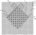
As shown in Figure 2, in permanent-magnet planar array implement example 1 preferred for this invention, 101,102,103 are respectively first, and second and the 3rd, they are orthogonal.Permanent magnet array 100 distributes on 101,102 planes.Magnet array 100 is Haier Bake array along first direction 101 and second direction 102 according to Halbach array(by first kind N utmost point square magnet 104, the second class S utmost point square magnet 105, the 3rd class combined magnet (comprising first prismatic magnet 106, the second prismatic magnet 107 and the triangular prism magnet 108)) pattern carries out periodicity and arranges.Wherein the 3rd class combined magnet is made up of the first prismatic magnet 106, the second prismatic magnet 107, triangular prism magnet 108 3 segment magnet pieces.Wherein this first kind N utmost point square magnet 104, the second class S utmost point square magnet 105 are respectively on the positive direction of the 3rd direction of principal axis 103 and the direction of magnetization on the negative direction, and they planar are alternately distributed, and spacing is p.Wherein, one group of first kind N utmost point square magnet 104 or the second class S utmost point square magnet 105 and 4 group of the 3rd class combined magnet (106,107,108) of its four edges radiation direction are configured to the basic unit of a magnet array, as shown in Figure 3.
Fig. 3 is an elementary cell of this Halbach magnet array among the embodiment 1.When this elementary cell center was first kind N utmost point square magnet 104,4 group of the 3rd class combined magnet (106,107,108) direction of magnetization of its four edges radiation direction was pointed to the direction of first kind N utmost point square magnet 104.When this elementary cell center was the second class S utmost point square magnet 105,4 group of the 3rd class combined magnet (106,107,108) direction of magnetization of its four edges radiation direction was pointed to the direction away from the second class S utmost point square magnet 105.The 3rd class combined magnet (106,107,108) is respectively the first, the second, the 3rd triangular column type magnet piece, and cross section is respectively right-angled triangle as shown in Figure 4, isosceles triangle and right-angled triangle, and they form a bar magnet jointly.This first kind, second class, the 3rd class magnet make up the Halbach group of magnets 121,122 of a complete cycle, distribute and repeat to arrange along first direction of principal axis 101 and 102 cycles of second direction, make up magnet array.
Fig. 4 be among the embodiment one this Halbach group of magnets along the sectional view of the periodicity magnet array of first direction 101 or second direction 102.Wherein, the first prismatic magnet 106 of the 3rd class magnet is along the vertical second prismatic magnet 107 that points to the 3rd class magnet of inclined-plane magnetizing direction, the pole orientation of the second prismatic magnet 107 of the 3rd class magnet and first direction 101 parallel sensing first kind N utmost point square magnets 104, the second prismatic magnet 107 of the triangular prism magnet 108 of the 3rd class magnet along inclined-plane magnetizing direction perpendicular distal from the 3rd class magnet, first kind square magnet 104a, 104b direction of magnetization parallel axes 103 upwards, the second class square magnet 105a, 105b direction of magnetization parallel axes 103 are downward.Length, the height, wide equal consistent of first kind square magnet 104a, 104b and the second class square magnet 105a, 105b, the length of first kind square magnet 104a, 104b and the 3rd class combined magnet is p, the second prismatic magnet 107 of described the 3rd class magnet is isosceles triangle, and its base length of side is tm.
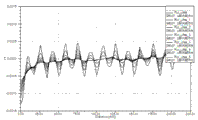
Fig. 5 be among the embodiment one this Halbach group of magnets along the close optimization curve of 103 axial magnetic of the periodicity magnet array of first direction of principal axis 101 or second direction 102.The transverse axis of Fig. 5 is that the second prismatic magnet 107 base length of sides are the ratio value sequence of tm and pole span length p, this ratio value sequence from 0 to 1.The longitudinal axis of Fig. 5 is first order harmonics (being shown as solid line among Fig. 5) and the 3rd order harmonics curve (being shown as dotted line among Fig. 5) of the close curve of space magnetic of this Halbach array magnet upper surface of Fig. 3 10mm position.Can optimize according to the close curve chart of this magnetic and to obtain the tm/p proportion: 0.35 ~ 0.7, the close high order harmonic component amplitude of the magnetic of this Halbach group of magnets is less relatively, especially at the tm/p proportion: 0.5 ~ 0.57 o'clock, the close high order harmonic component of the magnetic of this Halbach group of magnets reached and minimizes.Can optimize according to the close curve chart of this magnetic and to obtain the tm/p proportion: 0.3 ~ 0.4, the fundamental voltage amplitude maximization that the magnetic of this Halbach group of magnets is close, but corresponding high order harmonic component is also bigger.
Fig. 6 be among the embodiment one this Halbach group of magnets along the two-dimentional magnetic flux distribution curve of the periodicity magnet array of first direction of principal axis 101 or second direction 102.The terminal flux leakage that can obtain this distribution array according to this two dimension magnetic flux distribution curve is few, and weak side magnetic flux evenly distributes and reveals and lack, and strong side magnetic flux distribution cyclic variation is more intensive.
Fig. 7 is that this Halbach group of magnets is along the strong side magnetic flux contour of the periodicity magnet array of first direction of principal axis 101 or second direction 102 among the embodiment one, and the strong side magnetic flux that can obtain this distribution array according to this two dimension magnetic flux distribution curve is the standard sine distribution.
Fig. 8 be among the embodiment one this Halbach group of magnets along the weak side magnetic flux contour of the periodicity magnet array of first direction of principal axis 101 or second direction 102, the weak side magnetic flux that can obtain this distribution array according to this two dimension magnetic flux distribution curve is Sine distribution, and the magnetic flux amplitude fluctuations of leakage is less.
Fig. 9 is the close distribution map of three-dimensional magnetic of 10mm position for this Halbach group of magnets among the embodiment 1 at the strong side height of plane coordinates internal magnet along the periodicity magnet array of first direction of principal axis 101 and second direction 102.The close space two-dimensional ideal sinusoidal that is of three dimensions magnetic that can obtain this distribution array according to this two dimension magnetic flux distribution curve distributes.
Embodiment two:
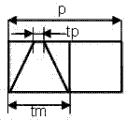
Figure 10 has provided second kind of embodiment of magnet array among Fig. 1.As shown in figure 10, embodiment two is that this Halbach group of magnets is along the sectional view of the periodicity magnet array of first direction of principal axis 101 or second direction 102.This array comprises three class magnet, wherein, the first prismatic magnet 136 of the 3rd class magnet is along the vertical second prismatic magnet 137 that points to the 3rd class magnet of inclined-plane magnetizing direction, the pole orientation of the second prismatic magnet 137 of the 3rd class magnet and first direction of principal axis, 101 parallel sensing first kind N utmost point square magnet 134, the second prismatic magnet 107 of the triangular prism magnet 138 of the 3rd class magnet along inclined-plane magnetizing direction perpendicular distal from the 3rd class magnet, first kind N utmost point square magnet 134a, 134b direction of magnetization parallel axes 103 makes progress the second class S utmost point square magnet 135a, 135b direction of magnetization parallel axes 103 is downward.As shown in figure 11, first kind N utmost point square magnet 134a, the 134b of the Halbach group of magnets that Figure 10 provides and the second class S utmost point square magnet 135a, the length of 135b, height, wide equal consistent, the length of first kind N utmost point square magnet 134a, 134b and the 3rd class combined magnet is p, the second prismatic magnet 137 of described the 3rd class magnet is isosceles trapezoid, its bottom length of side is tm, and the last base length of side is tp.
Figure 12 be among the embodiment two this Halbach group of magnets along the close optimization curve of magnetic of the third direction 103 of the periodicity magnet array of first direction 101 or second direction 102.The transverse axis of Figure 12 is that the last base length of side tp of the second prismatic magnet 137 and the bottom length of side are the ratio value sequence between the tm, this ratio value sequence from 0 to 1; The longitudinal axis of Figure 12 is the first-harmonic curve of the close curve of space magnetic of this Halbach array magnet upper surface of Figure 10 10mm position.Can optimize according to the close curve chart of this magnetic and to obtain the tp/tm proportion: 0 ~ 0.3, the space magnetic of this Halbach group of magnets is close to reach maximization.Especially, this ratio value was got 0 o'clock, was the situation of embodiment 1, and therefore, it is 0 particular example that embodiment one is tp.
Embodiment three:
Figure 13 has provided the third embodiment of magnet array among Fig. 1, and as shown in figure 13, embodiment three is that this Halbach group of magnets is along the sectional view of the periodicity magnet array of first direction 101 or second direction 102.This array comprises three class magnet, wherein, first magnet 335 of the 3rd class magnet and the 101 parallel sensings of first direction of principal axis are also pointed to the pole orientation and the extremely trapezoidal prismatic magnet 337 of first direction of principal axis, 101 parallel sensing first kind N of second magnet 336 of extremely trapezoidal prismatic magnet 337, the three class magnet of first kind N.First kind cross section be trapezoidal prismatic magnet 337a, 337b direction of magnetization parallel axes 103 upwards, the second class cross section is that trapezoidal prismatic magnet 338a, 338b direction of magnetization parallel axes 103 is downward.As shown in figure 13, the first kind magnet of this Halbach group of magnets, the second class magnet and the 3rd class magnet are trapezoid cross section magnet, and their width is all consistent.First kind square magnet 337a, 337b among this embodiment 3 and the length of the 3rd class combined magnet are p, and the second prismatic magnet 137 of described the 3rd class magnet is isosceles trapezoid, and its bottom length of side is tm, and the last base length of side is tp.Preferably, the last base length of side of the 3rd class magnet of this embodiment 3 be tp with the bottom length of side is that the ratio scope of tm is: 0 ~ 0.5; The last base length of side of the 3rd class magnet is tp: 0 ~ 0.25.
Embodiment four:
Figure 14 has provided the 4th kind of embodiment of magnet array among Fig. 1.As shown in figure 14, embodiment 4 is that this Halbach group of magnets is along the sectional view of the periodicity magnet array of first direction of principal axis 101 or second direction 102.This array comprises three class magnet: first kind magnet 234, the second class magnet 235 and the 3rd class magnet 236,237,238.Wherein, the first prismatic magnet 236 of the 3rd class magnet is along the vertical second prismatic magnet 237 that points to the 3rd class magnet of inclined-plane magnetizing direction, the pole orientation of the second prismatic magnet 237 of the 3rd class magnet and first direction of principal axis, 101 parallel sensing first kind N utmost point square magnet 234, the second prismatic magnet 237 of the triangular prism magnet 238 of the 3rd class magnet along inclined-plane magnetizing direction perpendicular distal from the 3rd class magnet, first kind N utmost point square magnet 234a, 234b direction of magnetization parallel axes 103 upwards, the second class S utmost point square magnet 235a, 235b direction of magnetization parallel axes 103 are downward.As shown in figure 15, first kind N utmost point square magnet 234a, the 234b of the Halbach group of magnets that Figure 14 provides and the second class S utmost point square magnet 235a, the length of 235b, height, wide equal consistent, wherein highly be H, the length of first kind N utmost point square magnet 234a, 234b and the 3rd class combined magnet is p, the second prismatic magnet 237 of described the 3rd class magnet is isosceles trapezoid, its bottom length of side is tm, the first prismatic magnet 236 and the triangular prism magnet 238 of described the 3rd class magnet are the quadrangular magnet in right-angled trapezium cross section, the length of side th of its combinatorial surface.Preferably, the base tm of the second prismatic magnet 237 of described the 3rd class magnet and the proportion of pole span length p are: 0.35 ~ 0.7, and the first prismatic magnet 236 of described the 3rd class magnet and the length of side th of the combinatorial surface of triangular prism magnet 238 and the proportion of magnet height H are: 0 ~ 0.5.
Need to prove, technical scheme of the present invention is not limited to magnet unit and the magnet array structure in the various embodiments described above, those skilled in the art fully can be according to the technological know-how of overall plan of the present invention and this area, characteristics such as the form of the composition of design and change magnet unit of the present invention, parameter: the prismatic magnet that for example adopts other cross sectional shapes, perhaps magnet such as terrace with edge, pyramid shape constitutes the magnet combination of Halbach array arrangement, select geomery parameter, the direction of magnetization of each magnet according to design requirement and the close characteristic of magnetic, etc.
The present invention proposes a kind of magnetic-floating plane motor locating device of more continuous Halbach magnet array newly, the main pole of the planar motor magnet array of this device adopts square magnet array, the 3rd class magnetic pole adopt triangular prism magnet with or quadrangular magnet totally three blocks of magnet make up, triangular in shape or the trapezoidal topological structure layout in cross section, magnetic close direction in plane is consistent with magnet array profile direction, and the magnetic of structure is close to be more continuous Halbach array.Simultaneously, the topological structure of this magnet array makes vertical and horizontal magnetic close all relative bigger, and it is littler that back side magnetic is revealed, and the close high order harmonic component of planar magnetic is littler.
Figure 16 has provided magnetic-floating plane motor according to the present invention is applied to the step-scan exposure as the moving magnet positioner lithographic equipment in more detail, its building block comprises: lighting module 7101, illumination support 7102, mask 7103, mask platform planar motor 7104, mask platform brace summer 7112, object lens 7105, mask platform support frame 7110, main substrate 7111, interferometer measurement module 7120, silicon chip 7106, wafer-supporting platform 7107, the magnet mover 7108 of planar motor, planar motor coil stator and pedestal 7109, carriage stand 7113, and basic framework 7115.Wherein, mask platform planar motor 7104 and work stage planar motor 7108,7109 have all adopted moving magnet magnetic-floating plane motor of the present invention as the bogey of figure and substrate, and the planar motor magnet array of two motion positions platforms and coil array are arranged as previously mentioned.
The coil stator of mask platform planar motor 7104 is installed on the mask platform brace summer 7112, and work stage planar motor 7108 suspension location, its stator coil stator is installed on the pedestal 7109.The mover of work stage magnetic-floating plane motor adopts laser interferometer 7120 to measure feedback and controls, in coil, pass to electric current, the position that obtains according to interferometer measurement, the size and Orientation of controlling the power of tuning planar motor controller, and then the size of current of control plane motor, thereby the position of accurate positioning pattern and substrate.In the exposure process, the light transmission of lighting module 7101 is crossed mask 7103 figure is projected on substrate or the silicon chip 7106 according to multiplying power by object lens 7105, depicts figure.
This is preferred embodiment of the present invention in this specification, and above embodiment is only in order to illustrate technical scheme of the present invention but not limitation of the present invention.All those skilled in the art all should be within the scope of the present invention under this invention's idea by the available technical scheme of logical analysis, reasoning, or a limited experiment.
Claims (15)
1. cross magnet unit, comprise that first magnet reaches second magnet unit around first magnet, it is characterized in that, described first magnet is N utmost point magnet or S utmost point magnet, the direction of magnetization of described first magnet is along Z-direction, described second magnet unit comprises four groups of magnet combinations that structure is identical, described four groups of magnet combination lays respectively at along X-direction with along Y direction, the direction of magnetization of described magnet combination is pointed to N utmost point magnet or away from S utmost point magnet, and described every group of magnet combination is made up of at least two prismatic magnet or pyramid magnet or terrace with edge magnet.
2. cross magnet unit as claimed in claim 1, it is characterized in that, described second magnet unit is a cuboid, and the combination of described magnet is formed a cuboid by the first prismatic magnet, the second prismatic magnet and triangular prism magnet, and is described first, the triangular prism magnet arrangement is identical.
3. cross magnet unit as claimed in claim 2, it is characterized in that, described first, triangular prism magnet is a right angle triangle along the cross section on XZ or YZ plane, the cross section of the described second prismatic magnet is an isoceles triangle shape, its bottom length of side is tm, described first magnet be adjacent second magnet unit the combination of arbitrary group of magnet length and be p, the span of tm/p is 0.35 ~ 0.7.
4. cross magnet unit as claimed in claim 3 is characterized in that, the span of described tm/p is 0.5 ~ 0.57.
5. cross magnet unit as claimed in claim 2, it is characterized in that, described first, triangular prism magnet is a right angle triangle along the cross section on XZ or YZ plane, the described second prismatic magnet is that isosceles are trapezoidal along the cross section on XZ or YZ plane, its upper base base length of side is tp, the bottom length of side is tm, and wherein the span of tp/tm is 0 ~ 0.3.
6. cross magnet unit as claimed in claim 2, it is characterized in that, described first, triangular prism magnet is that a right angle is trapezoidal along the cross section on XZ or YZ plane, base length of side is th on it, the bottom length of side is H, the described second prismatic magnet is an isoceles triangle shape along the cross section on XZ or YZ plane, its base length of side is tm, described first magnet be adjacent second magnet unit the combination of arbitrary group of magnet length and be P, the span of tp/tm is that the span of 0.35 ~ 0.7, th/H is 0 ~ 0.5.
7. cross magnet unit as claimed in claim 1, it is characterized in that, described first magnet unit and second magnet unit are trapezoidal, wherein the upper base base length of side of second magnet unit is tp, the bottom length of side is tm, the length of the combination of arbitrary group of magnet and first magnet and be p, the span of tp/tm is that the span of 0 ~ 0.5, tm/p is 0 ~ 0.25.
8. as each described cross magnet unit in the claim 3,5,6, it is characterized in that, the direction of magnetization of the described second prismatic magnet is along X-direction or Y direction, and the direction of magnetization of the described first prismatic magnet and triangular prism magnet is corresponding isosceles edge direction perpendicular to the second prismatic magnet respectively.
9. magnet array, it is characterized in that, comprise that several are as each described magnet unit of claim 1 to 7, described magnet unit carries out periodicity along first direction of principal axis and second direction of principal axis according to the Halbach array pattern and arranges, described Halbach array pattern is that a N utmost point magnet and a S utmost point magnet are connected by one group of magnet in second magnet unit, and the direction of magnetization of described magnet combination is pointed to a described N utmost point magnet and away from a S utmost point magnet.
10. magnetic-floating plane motor, comprise magnet array and coil array, it is characterized in that, described magnet array comprises that several are as each described magnet unit of claim 1 to 7, described magnet unit carries out the periodicity composition of arranging along first direction of principal axis and second direction of principal axis according to the Halbach array pattern, described Halbach array pattern is that a N utmost point magnet and a S utmost point magnet are connected by one group of magnet in second magnet unit, and the direction of magnetization of described magnet combination is pointed to a described N utmost point magnet and away from a S utmost point magnet; Described coil array be positioned on the magnet array or under, described magnet array moves with respect to described coil array.
11. magnetic-floating plane motor as claimed in claim 10, it is characterized in that, described coil array comprises the coil unit that several distribute along first direction of principal axis, second direction of principal axis, described first direction of principal axis, second direction of principal axis respectively with directions X, Y-direction in angle of 45 degrees.
12. magnetic-floating plane motor as claimed in claim 11 is characterized in that, described coil unit comprises four coil groups of rectangular arrangement, and wherein adjacent two coil groups are corresponding respectively arranges along first direction of principal axis, second direction of principal axis.
13. magnetic-floating plane motor as claimed in claim 12 is characterized in that, described coil groups comprises four groups of coils that are parallel to each other, and described four groups of coils are formed the coil stator array.
14. a lithographic equipment is characterized in that, comprising:
One lighting unit is used for providing exposing light beam;
One mask platform is used for supporting a mask;
One work stage is used for supporting a substrate and six-freedom motion being provided;
One projection objective is used for figure on the mask is projected to substrate by a certain percentage;
Described work stage comprises as each described magnetic-floating plane motor of claim 10 to 13.
15. lithographic equipment as claimed in claim 14 is characterized in that, described mask platform comprises as each described magnetic-floating plane motor of claim 10 to 13.
Priority Applications (1)
| Application Number | Priority Date | Filing Date | Title |
|---|---|---|---|
| CN201210013313.1A CN103208867B (en) | 2012-01-17 | 2012-01-17 | Magnet unit, magnet array, magnetic levitation planar motor and lithographic device using magnetic levitation planar motor |
Applications Claiming Priority (1)
| Application Number | Priority Date | Filing Date | Title |
|---|---|---|---|
| CN201210013313.1A CN103208867B (en) | 2012-01-17 | 2012-01-17 | Magnet unit, magnet array, magnetic levitation planar motor and lithographic device using magnetic levitation planar motor |
Publications (2)
| Publication Number | Publication Date |
|---|---|
| CN103208867A true CN103208867A (en) | 2013-07-17 |
| CN103208867B CN103208867B (en) | 2015-06-17 |
Family
ID=48755988
Family Applications (1)
| Application Number | Title | Priority Date | Filing Date |
|---|---|---|---|
| CN201210013313.1A Active CN103208867B (en) | 2012-01-17 | 2012-01-17 | Magnet unit, magnet array, magnetic levitation planar motor and lithographic device using magnetic levitation planar motor |
Country Status (1)
| Country | Link |
|---|---|
| CN (1) | CN103208867B (en) |
Cited By (12)
| Publication number | Priority date | Publication date | Assignee | Title |
|---|---|---|---|---|
| CN104218771A (en) * | 2014-09-28 | 2014-12-17 | 浙江理工大学 | Magnetic-suspension permanent-magnet synchronous planar motor with multiple degrees of freedom |
| WO2015101156A1 (en) * | 2013-12-31 | 2015-07-09 | 上海微电子装备有限公司 | Magnetic array and magnetic suspension planar motor |
| CN104901586A (en) * | 2014-03-03 | 2015-09-09 | 上海微电子装备有限公司 | Magnetic levitation planar motor |
| CN105159032A (en) * | 2015-08-18 | 2015-12-16 | 浙江欧视达科技有限公司 | Semiautomatic solder-resist exposure machine |
| WO2016072668A1 (en) * | 2014-11-04 | 2016-05-12 | 한국전기연구원 | Movable element having two-dimensional halbach array without nonmagnetic space |
| WO2017042273A1 (en) * | 2015-09-11 | 2017-03-16 | Beckhoff Automation Gmbh | Magnetic assembly for an electric motor |
| CN106936337A (en) * | 2015-12-30 | 2017-07-07 | 上海微电子装备有限公司 | Magnetic-floating plane electric rotating machine and lithographic equipment |
| CN107612232A (en) * | 2017-09-27 | 2018-01-19 | 西安工程大学 | The miniature planar motor apparatus and its driving method of a kind of electromagnetic digital array of actuators |
| CN108964404A (en) * | 2018-07-18 | 2018-12-07 | 中国石油大学(华东) | A kind of novel permanent-magnet planar motor and its decoupling algorithm |
| CN111404440A (en) * | 2020-04-02 | 2020-07-10 | 深圳大学 | Moving magnet type magnetic suspension planar motor and reversing method and reversing device thereof |
| WO2022016872A1 (en) * | 2020-07-21 | 2022-01-27 | 清华大学 | Output compensation method and device for sine error of motor under interference magnetic field |
| CN114352616A (en) * | 2021-12-31 | 2022-04-15 | 哈尔滨工业大学 | Halbach array assembling method for magnetic levitation moving table |
Citations (5)
| Publication number | Priority date | Publication date | Assignee | Title |
|---|---|---|---|---|
| US6285097B1 (en) * | 1999-05-11 | 2001-09-04 | Nikon Corporation | Planar electric motor and positioning device having transverse magnets |
| CN101515119A (en) * | 2009-04-03 | 2009-08-26 | 清华大学 | Silicon chip bench double-bench switching system employing air floatation plane motor |
| CN101610054A (en) * | 2009-07-21 | 2009-12-23 | 清华大学 | Adopt the planar motor of three-dimensional permanent magnet array |
| CN102097982A (en) * | 2011-02-24 | 2011-06-15 | 华中科技大学 | Permanent-magnet synchronous magnetic suspension planar motor |
| US20120119861A1 (en) * | 2010-11-16 | 2012-05-17 | Plasma Innovation Llc | Permanent Magnets Array for Planar Magnetron |
-
2012
- 2012-01-17 CN CN201210013313.1A patent/CN103208867B/en active Active
Patent Citations (5)
| Publication number | Priority date | Publication date | Assignee | Title |
|---|---|---|---|---|
| US6285097B1 (en) * | 1999-05-11 | 2001-09-04 | Nikon Corporation | Planar electric motor and positioning device having transverse magnets |
| CN101515119A (en) * | 2009-04-03 | 2009-08-26 | 清华大学 | Silicon chip bench double-bench switching system employing air floatation plane motor |
| CN101610054A (en) * | 2009-07-21 | 2009-12-23 | 清华大学 | Adopt the planar motor of three-dimensional permanent magnet array |
| US20120119861A1 (en) * | 2010-11-16 | 2012-05-17 | Plasma Innovation Llc | Permanent Magnets Array for Planar Magnetron |
| CN102097982A (en) * | 2011-02-24 | 2011-06-15 | 华中科技大学 | Permanent-magnet synchronous magnetic suspension planar motor |
Non-Patent Citations (1)
| Title |
|---|
| LI HUANG ETC: "Comparative Study of Magnetic Fields Due to Types of Planar Permanent Magnet Array", 《 INTERNATIONAL CONFERENCE ON ELECTRICAL AND CONTROL ENGINEERING》 * |
Cited By (19)
| Publication number | Priority date | Publication date | Assignee | Title |
|---|---|---|---|---|
| WO2015101156A1 (en) * | 2013-12-31 | 2015-07-09 | 上海微电子装备有限公司 | Magnetic array and magnetic suspension planar motor |
| CN104901586A (en) * | 2014-03-03 | 2015-09-09 | 上海微电子装备有限公司 | Magnetic levitation planar motor |
| CN104901586B (en) * | 2014-03-03 | 2018-01-19 | 上海微电子装备(集团)股份有限公司 | Levitation planar motor |
| CN104218771A (en) * | 2014-09-28 | 2014-12-17 | 浙江理工大学 | Magnetic-suspension permanent-magnet synchronous planar motor with multiple degrees of freedom |
| WO2016072668A1 (en) * | 2014-11-04 | 2016-05-12 | 한국전기연구원 | Movable element having two-dimensional halbach array without nonmagnetic space |
| CN105159032A (en) * | 2015-08-18 | 2015-12-16 | 浙江欧视达科技有限公司 | Semiautomatic solder-resist exposure machine |
| CN107925338A (en) * | 2015-09-11 | 2018-04-17 | 倍福自动化有限公司 | The magnetic combination of motor |
| US10291085B2 (en) | 2015-09-11 | 2019-05-14 | Beckhoff Automation Gmbh | Magnetic assembly for an electric motor |
| WO2017042273A1 (en) * | 2015-09-11 | 2017-03-16 | Beckhoff Automation Gmbh | Magnetic assembly for an electric motor |
| CN106936337B (en) * | 2015-12-30 | 2019-02-01 | 上海微电子装备(集团)股份有限公司 | Magnetic-floating plane rotating electric machine and lithographic equipment |
| CN106936337A (en) * | 2015-12-30 | 2017-07-07 | 上海微电子装备有限公司 | Magnetic-floating plane electric rotating machine and lithographic equipment |
| CN107612232A (en) * | 2017-09-27 | 2018-01-19 | 西安工程大学 | The miniature planar motor apparatus and its driving method of a kind of electromagnetic digital array of actuators |
| CN107612232B (en) * | 2017-09-27 | 2019-05-17 | 西安工程大学 | A kind of the miniature planar motor apparatus and its driving method of electromagnetic digital array of actuators |
| CN108964404A (en) * | 2018-07-18 | 2018-12-07 | 中国石油大学(华东) | A kind of novel permanent-magnet planar motor and its decoupling algorithm |
| CN111404440A (en) * | 2020-04-02 | 2020-07-10 | 深圳大学 | Moving magnet type magnetic suspension planar motor and reversing method and reversing device thereof |
| CN111404440B (en) * | 2020-04-02 | 2023-11-24 | 深圳大学 | Moving magnet type magnetic suspension planar motor and reversing method and reversing device thereof |
| WO2022016872A1 (en) * | 2020-07-21 | 2022-01-27 | 清华大学 | Output compensation method and device for sine error of motor under interference magnetic field |
| CN114352616A (en) * | 2021-12-31 | 2022-04-15 | 哈尔滨工业大学 | Halbach array assembling method for magnetic levitation moving table |
| CN114352616B (en) * | 2021-12-31 | 2022-07-19 | 哈尔滨工业大学 | Halbach array assembling method for magnetic levitation moving table |
Also Published As
| Publication number | Publication date |
|---|---|
| CN103208867B (en) | 2015-06-17 |
Similar Documents
| Publication | Publication Date | Title |
|---|---|---|
| CN103208867B (en) | Magnet unit, magnet array, magnetic levitation planar motor and lithographic device using magnetic levitation planar motor | |
| US9755493B2 (en) | Linear motor and stage apparatus | |
| Lu | 6D direct-drive technology for planar motion stages | |
| CN101807010B (en) | Nano-precision six-freedom-degree magnetic suspension jiggle station and application | |
| CN101609265B (en) | Silicon slice platform multi-platform exchange system adopting magnetic levitation planar motor | |
| CN101694560B (en) | Silicon wafer stage double-stage exchange system by adopting air-floatation planar motor | |
| CN103454864B (en) | The magnetic that a kind of thick essence moves one floats mask table system | |
| KR100726711B1 (en) | Wide area movement stage with magnetic levitation technology | |
| CN103066894A (en) | Six degrees of freedom magnetic levitation workpiece table | |
| CN101515119A (en) | Silicon chip bench double-bench switching system employing air floatation plane motor | |
| CN101527484A (en) | Gas-magnet mixing suspended planar motor with easily expanded horizontal stroke | |
| CN105811730B (en) | A kind of six degree of freedom linear motor | |
| CN103186058B (en) | Mask platform system with six-degree-of-freedom coarse drive platform | |
| CN104901586B (en) | Levitation planar motor | |
| CN103105743B (en) | Mask table system with plane diffraction grating measurement and having six freedom degrees macro platform | |
| CN103105742B (en) | Mask table system of six-degree-of-freedom coarse table with photoelectric position detector measurement function | |
| CN103116250B (en) | Masking platform system with laser interferometer measurement and six-freedom-degree coarse movement platform | |
| WO2023226272A1 (en) | Magnetic suspension planar motor workbench with double-layer winding coarse-fine drive | |
| CN109870881A (en) | The macro box-like long stroke precision movement platform of micro-group | |
| CN101610022A (en) | A kind of planar motor that adopts groove-type coil | |
| CN111490642B (en) | Displacement device based on Hall effect sensor and planar motor | |
| JP5140103B2 (en) | Linear motor pair, moving stage, and electron microscope | |
| CN106933052B (en) | A kind of litho machine sports platform system and litho machine | |
| CN112436711B (en) | Displacement device | |
| CN201378784Y (en) | Gas-magnetic mixture suspension plane motor with easy extension horizontal stroke |
Legal Events
| Date | Code | Title | Description |
|---|---|---|---|
| C06 | Publication | ||
| PB01 | Publication | ||
| C10 | Entry into substantive examination | ||
| SE01 | Entry into force of request for substantive examination | ||
| C14 | Grant of patent or utility model | ||
| GR01 | Patent grant | ||
| CP01 | Change in the name or title of a patent holder | ||
| CP01 | Change in the name or title of a patent holder |
Address after: 201203 Shanghai Zhangjiang High Tech Park of Pudong New Area Zhang Road No. 1525 Patentee after: Shanghai microelectronics equipment (Group) Limited by Share Ltd Address before: 201203 Shanghai Zhangjiang High Tech Park of Pudong New Area Zhang Road No. 1525 Patentee before: Shanghai Micro Electronics Equipment Co., Ltd. |