CN103174618A - Radial plunger hydraulic pump of double-acting type outer rotor - Google Patents
Radial plunger hydraulic pump of double-acting type outer rotor Download PDFInfo
- Publication number
- CN103174618A CN103174618A CN2013101092330A CN201310109233A CN103174618A CN 103174618 A CN103174618 A CN 103174618A CN 2013101092330 A CN2013101092330 A CN 2013101092330A CN 201310109233 A CN201310109233 A CN 201310109233A CN 103174618 A CN103174618 A CN 103174618A
- Authority
- CN
- China
- Prior art keywords
- oil
- plunger
- spool
- cam
- stator
- Prior art date
- Legal status (The legal status is an assumption and is not a legal conclusion. Google has not performed a legal analysis and makes no representation as to the accuracy of the status listed.)
- Granted
Links
Images


Landscapes
- Reciprocating Pumps (AREA)
Abstract
一种双作用式外转子的径向柱塞液压泵,采用外转子内定子结构,转子内部分别安装有一对吸油径向凸轮和一个压油径向凸轮,通过凸轮传动,实现柱塞沿着径向的直线往复运动,获得压力油液,该径向凸轮通过低摩擦的滚动方式将动力传递到柱塞上;每个柱塞缸的配油采用滑阀与吸油口、排油口交替连通的方式,滑阀阀芯的直线移动依靠转子内部两轴向端面板上对称布置的轴向凸轮驱动,该轴向凸轮通过低摩擦的滚动方式将动力传递到滑阀阀芯上,从而切换柱塞腔与进油孔或者出油孔的连通,配油轴与缸体均不旋转,密封可靠、泄露量小。本发明的外转子内定子径向柱塞液压泵,具有结构紧凑、容积效率高、磨耗小、受力对称的优点。
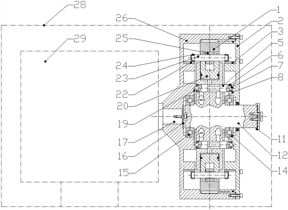
A double-acting external rotor radial plunger hydraulic pump adopts an external rotor internal stator structure. A pair of oil-absorbing radial cams and an oil-pressing radial cam are respectively installed inside the rotor. Direct linear reciprocating motion to obtain pressurized oil, the radial cam transmits power to the plunger through low-friction rolling; the oil distribution of each plunger cylinder adopts a sliding valve that communicates alternately with the oil suction port and the oil discharge port In this way, the linear movement of the spool of the spool is driven by the axial cams arranged symmetrically on the two axial end panels inside the rotor. The cavity is connected with the oil inlet hole or the oil outlet hole, the oil distribution shaft and the cylinder body do not rotate, the seal is reliable, and the leakage is small. The outer rotor inner stator radial plunger hydraulic pump of the present invention has the advantages of compact structure, high volumetric efficiency, small wear and symmetrical force.
Description
技术领域 technical field
本发明属于径向柱塞液压泵技术领域,具体涉及一种双作用式外转子的径向柱塞液压泵。 The invention belongs to the technical field of radial plunger hydraulic pumps, in particular to a radial plunger hydraulic pump with a double-acting outer rotor. the
背景技术 Background technique
液压泵是液压技术领域的核心部件,用于为系统提供具有稳定流量和压力的高压油液。液压泵性能的好坏对液压系统的性能起着至关重要的作用。径向柱塞液压泵以其容积效率高、寿命长、运转平稳的优点,广泛运用于冶金、矿山、锻压等机械设备中。 The hydraulic pump is the core component in the field of hydraulic technology, which is used to provide high-pressure oil with stable flow and pressure for the system. The performance of the hydraulic pump plays a vital role in the performance of the hydraulic system. Radial piston hydraulic pumps are widely used in metallurgy, mining, forging and other mechanical equipment due to their advantages of high volumetric efficiency, long life and stable operation. the
传统的径向柱塞液压泵采用的都是内转子结构,柱塞液压泵工作时,用来产生液压的柱塞和缸体均转动,依靠离心力和泵体内壁的反作用力,使柱塞沿径向往复运动;其配油方式为配油轴配油,配油轴与转子之间存在一定的间隙。传统径向柱塞液压泵由于是柱塞缸体随传动轴一起转动,因此转动惯量较大,油液随缸体高速转动容易产生气泡,不利于提高泵的容积效率,又因配流轴与转子之间存在间隙,油液的泄露也会进一步降低泵的容积效率;传统径向柱塞液压泵工作时配油轴受到径向不平衡的液压力作用,易于磨损。 The traditional radial plunger hydraulic pump adopts the internal rotor structure. When the plunger hydraulic pump is working, the plunger and the cylinder used to generate hydraulic pressure rotate, relying on the centrifugal force and the reaction force of the inner wall of the pump to make the plunger move along the Radial reciprocating movement; the oil distribution method is the oil distribution shaft, and there is a certain gap between the oil distribution shaft and the rotor. Because the traditional radial plunger hydraulic pump is that the plunger cylinder rotates together with the drive shaft, the moment of inertia is large, and the oil is prone to air bubbles when the cylinder rotates at high speed, which is not conducive to improving the volumetric efficiency of the pump. There is a gap between them, and the leakage of oil will further reduce the volumetric efficiency of the pump; when the traditional radial piston hydraulic pump is working, the oil distribution shaft is subjected to radial unbalanced hydraulic pressure, which is easy to wear. the
发明内容 Contents of the invention
为了克服上述现有技术的缺点,本发明的目的在于提出一种双作用式外转子的径向柱塞液压泵,具有结构紧凑、容积效率高、磨耗低、 可双向工作的优点。 In order to overcome the above-mentioned shortcomings of the prior art, the object of the present invention is to propose a radial plunger hydraulic pump with double-acting outer rotor, which has the advantages of compact structure, high volumetric efficiency, low wear, and can work in both directions. the
为了达到上述目的,本发明采取的技术方案为: In order to achieve the above object, the technical scheme that the present invention takes is:
一种双作用式外转子的径向柱塞液压泵,包括转子壳体26,转子壳体26安装在电机29的传动轴17上并用传动轴压盖16压紧,转子端盖2安装在转子壳体26上,转子壳体26的内侧分别设有第一滑阀阀芯驱动曲面19和第一圆柱面21,转子端盖2的内侧分别设有第二滑阀阀芯驱动曲面8和第二圆柱面4,转子壳体26的顶部中心设有台肩27,第一滚动轴承15安装在第一滑阀阀芯驱动曲面19内孔内,第二滚动轴承14安装在第二滑阀阀芯驱动曲面8内孔内,第一吸油凸轮22安装在第一圆柱面21上,第二吸油凸轮3安装在第二圆柱面4上,压油凸轮1安装在台肩27上,第一滚动轴承15、第二滚动轴承14支承着定子12,定子12的外圆柱面上均布有两个以上的柱塞孔,每个柱塞孔内都安装有柱塞20,每个柱塞20上都安装有柱塞销轴23,柱塞销轴23中间安装有压入滚动套25,两端安装有顶出滚动套24,顶出滚动套24压在第一吸油凸轮22和第二吸油凸轮3上,压入滚动套25抵在压油凸轮1上,定子12的端面上还均布有两个以上的通孔,这些通孔分别通过柱塞腔通油孔10与每个柱塞腔37相连通,且每个通孔内都装有滑阀阀芯5,滑阀阀芯5两端安装有滑阀滚珠压盖6,滑阀滚珠压盖6内安装有滑阀滚珠7,滑阀滚珠7能够自由转动,滑阀阀芯5两端的滑阀滚珠7分别顶在第一滑阀阀芯驱动曲面19、第二滑阀阀芯驱动曲面8上,定子轴端盖11安装在定子12端部,进油管、出油管分别连接在定子12的进、出油孔上,定子 12与外壳体28固定连接;
A radial plunger hydraulic pump with a double-acting external rotor, including a
泵的转动部分位于定子12外部,柱塞20的运动由压油凸轮1和第一吸油凸轮22、第二吸油凸轮3驱动,第一吸油凸轮22、第二吸油凸轮3的外圆柱面为椭圆柱面,压油凸轮1的内圆柱面为椭圆柱面,柱塞20的受力通过柱塞销轴23传递;当转子壳体26转动时,带动第一吸油凸轮22、第二吸油凸轮3和压油凸轮1转动,将圆周划分为两个吸油区和两个压油区,在吸油区,第一吸油凸轮22、第二吸油凸轮3的曲率半径由小变大,顶出滚动套24被顶起,再通过柱塞销轴23传递给柱塞20,使柱塞腔37容积增大实现吸油;在压油区,压油凸轮1曲率半径由大变小,压入滚动套25被压下,在通过柱塞销轴23传递给柱塞20,使柱塞腔37容积减小实现压油;
The rotating part of the pump is located outside the
泵的配油通过滑阀阀芯5的动作来实现,具体为:定子12内部设有两个以上的孔道,分布在配油面A和配油面B上,配油面A和配油面B之间的距离小于定子宽度且大于滑阀阀芯5的细杆段的长度,配油面A和配油面B上分别设有吸油分配槽31和压油汇聚槽33,配油面A和配油面B上的半径方向还都设有辐射状油孔35,辐射状油孔35外端分别与各相应位置的阀芯通孔连通,内端分别与各自所在平面上的吸油分配槽31或者压油汇聚槽33连通,在定子12的轴向还开有吸油孔30和高压油输出孔34,吸油孔30将吸油分配槽31与进油管9连通,高压油输出孔34将压油汇聚槽33与出油管13连通。
The oil distribution of the pump is realized by the action of the
所述的第一滑阀阀芯驱动曲面19、第二滑阀阀芯驱动曲面8与以中轴线为轴心的任意圆柱面的交线的展开线都为余弦曲线,即转子 壳体26转动一周,滑阀滚珠7与第一滑阀阀芯驱动曲面19、第二滑阀阀芯驱动曲面8的接触线是一条卷起的余弦曲线,余弦曲线的幅值就是滑阀阀芯5从中位运动到左位或者右位的行程,转子壳体26和转子端盖2上的第一滑阀阀芯驱动曲面19、第二滑阀阀芯驱动曲面8是一对等距曲面。
The expansion lines of the intersection lines of the first slide valve spool driving
本发明具有以下优点: The present invention has the following advantages:
1)结构紧凑、容积效率高。该泵采用外转子内定子结构,结构设计紧凑,定子上的柱塞腔不转动,避免油液在高速转动时产生气泡;柱塞缸体和配流轴为一个整体零件,避免了油液泄露造成的容积效率下降。 1) Compact structure and high volumetric efficiency. The pump adopts the structure of outer rotor and inner stator, and the structure design is compact. The plunger chamber on the stator does not rotate to avoid air bubbles when the oil rotates at high speed; the plunger cylinder and the distribution shaft are an integral part, which avoids oil leakage. volumetric efficiency drops. the
2)双作用、静压平衡。该泵为对称结构,对径向的液压力可以实现自平衡,减少了对传动轴的削弱,泵转子转动一周可以实现两次吸油和压油。 2) Double action, static pressure balance. The pump has a symmetrical structure, which can achieve self-balancing for the radial hydraulic pressure, reducing the weakening of the transmission shaft, and the pump rotor can realize two times of oil suction and oil pressure after one rotation. the
3)磨耗低。泵内的主要摩擦副均为滚动摩擦,磨耗低、寿命长。 3) Low wear and tear. The main friction pair in the pump is rolling friction, which has low wear and long service life. the
4)可双向工作,能够用于构建泵直驱系统。该泵进、出油通路对称,吸油、排油过程完全隔绝,电机正反转都能实现良好密封,故可以通过改变电机转向,调转吸油、压油方向,能够用于构建泵直驱系统。 4) It can work in both directions and can be used to build a pump direct drive system. The oil inlet and outlet passages of the pump are symmetrical, the oil suction and oil discharge processes are completely isolated, and the motor can achieve good sealing in both forward and reverse directions. Therefore, the direction of oil suction and oil pressure can be reversed by changing the direction of the motor, and can be used to build a pump direct drive system. the
附图说明 Description of drawings
图1为本发明滑阀阀芯位于左位的轴向剖视图。 Fig. 1 is an axial sectional view of the spool of the present invention in the left position. the
图2为本发明滑阀阀芯位于右位的轴向剖视图。 Fig. 2 is an axial sectional view of the spool of the present invention in the right position. the
图3为图1配油面A-A的剖视图。 Fig. 3 is a sectional view of the oil distribution surface A-A of Fig. 1 . the
图4为图1配油面B-B的剖视图。 Fig. 4 is a sectional view of oil distribution surface B-B in Fig. 1 . the
图5为转动部分中间径向剖面图。 Fig. 5 is a middle radial sectional view of the rotating part. the
图6滑阀阀芯驱动曲面图及柱塞运动规律图线。 Fig. 6 The driving surface diagram of the spool valve core and the diagram line of the plunger movement law. the
具体实施方式 Detailed ways
下面结合附图对本发明做详细描述。 The present invention will be described in detail below in conjunction with the accompanying drawings. the
参照图1和图2,一种双作用式外转子的径向柱塞液压泵,包括转子壳体26,转子壳体26安装在电机29的传动轴17上并用传动轴压盖16压紧,转子端盖2安装在转子壳体26上,转子壳体26的内侧分别设有第一滑阀阀芯驱动曲面19和第一圆柱面21,转子端盖2的内侧分别设有第二滑阀阀芯驱动曲面8和第二圆柱面4,转子壳体26的顶部中心设有台肩27,第一滚动轴承15安装在第一滑阀阀芯驱动曲面19内孔内,第二滚动轴承14安装在第二滑阀阀芯驱动曲面8内孔内,第一吸油凸轮22安装在第一圆柱面21上,第二吸油凸轮3安装在第二圆柱面4上,压油凸轮1安装在台肩27上,第一滚动轴承15、第二滚动轴承14支承着定子12,定子12的外圆柱面上均布有两个以上的柱塞孔,每个柱塞孔内都安装有柱塞20,每个柱塞20上都安装有柱塞销轴23,柱塞销轴23中间安装有压入滚动套25,两端安装有顶出滚动套24,顶出滚动套24压在第一吸油凸轮22和第二吸油凸轮3上,压入滚动套25抵在压油凸轮1上,定子12的端面上还均布有两个以上的通孔,这些通孔分别通过柱塞腔通油孔10与每个柱塞腔37相连通,且每个通孔内都装有滑阀阀芯5,滑阀阀 芯5两端安装有滑阀滚珠压盖6,滑阀滚珠压盖6内安装有滑阀滚珠7,滑阀滚珠7能够自由转动,滑阀阀芯5两端的滑阀滚珠7分别顶在第一滑阀阀芯驱动曲面19、第二滑阀阀芯驱动曲面8上,定子轴端盖11安装在定子12端部,进油管、出油管分别连接在定子12的进、出油孔上,定子12与外壳体28固定连接。
Referring to Fig. 1 and Fig. 2, a radial plunger hydraulic pump with a double-acting outer rotor includes a rotor housing 26, the rotor housing 26 is installed on the transmission shaft 17 of the motor 29 and is compressed with the transmission shaft gland 16, The rotor cover 2 is mounted on the rotor housing 26, the inner side of the rotor housing 26 is respectively provided with the first slide valve spool driving curved surface 19 and the first cylindrical surface 21, and the inner side of the rotor cover 2 is respectively provided with the second slide valve The spool driving curved surface 8 and the second cylindrical surface 4, the top center of the rotor housing 26 is provided with a shoulder 27, the first rolling bearing 15 is installed in the inner hole of the first slide valve spool driving curved surface 19, and the second rolling bearing 14 is installed in In the inner hole of the second spool driving curved surface 8, the first oil suction cam 22 is installed on the first cylindrical surface 21, the second oil suction cam 3 is installed on the second cylindrical surface 4, and the oil pressure cam 1 is installed on the shoulder 27 Above, the first rolling bearing 15 and the second rolling bearing 14 support the stator 12, and more than two plunger holes are evenly distributed on the outer cylindrical surface of the stator 12, and a plunger 20 is installed in each plunger hole, and each plunger A plunger pin shaft 23 is installed on the plug 20, a press-in rolling sleeve 25 is installed in the middle of the plunger pin shaft 23, and an ejection rolling sleeve 24 is installed at both ends, and the ejection rolling sleeve 24 is pressed against the first oil suction cam 22 and the second oil suction cam 22. On the second oil suction cam 3, the rolling
泵的转动部分位于定子12外部,柱塞20的运动由压油凸轮1和第一吸油凸轮22、第二吸油凸轮3驱动,第一吸油凸轮22、第二吸油凸轮3的外圆柱面为椭圆柱面,压油凸轮1的内圆柱面为椭圆柱面,柱塞20的受力通过柱塞销轴23传递;当转子壳体26以图1所示方向转动时,带动第一吸油凸轮22、第二吸油凸轮3和压油凸轮1转动,将圆周划分为两个吸油区和两个压油区,如图5所示,在吸油区,第一吸油凸轮22、第二吸油凸轮3的曲率半径由小变大,顶出滚动套24被顶起,再通过柱塞销轴23传递给柱塞20,使柱塞腔37容积增大实现吸油;在压油区,压油凸轮1曲率半径由大变小,压入滚动套25被压下,在通过柱塞销轴23传递给柱塞20,使柱塞腔37容积减小实现压油。
The rotating part of the pump is located outside the
泵的配油通过滑阀阀芯5的动作来实现,具体为:定子12内部设有两个以上的孔道,分布在配油面A和配油面B上,配油面A和配油面B之间的距离小于定子宽度且大于滑阀阀芯5的细杆段的长度,以保证配油孔道具有足够的壁厚,同时,配油面A和配油面B上的孔道之间能够实现良好的隔离,如图3、图4所示,配油面A和配油面B上分别设有吸油分配槽31和压油汇聚槽33,配油面A和配油面B 上的半径方向还都设有辐射状油孔35,辐射状油孔35外端分别与各相应位置的阀芯通孔连通,内端分别与各自所在平面上的吸油分配槽31或者压油汇聚槽33连通,在定子12的轴向还开有吸油孔30和高压油输出孔34,吸油孔30将吸油分配槽31与进油管9连通,高压油输出孔34将压油汇聚槽33与出油管13连通。
The oil distribution of the pump is realized by the action of the
所述的第一滑阀阀芯驱动曲面19、第二滑阀阀芯驱动曲面8与以中轴线为轴心的任意圆柱面的交线的展开线都为余弦曲线,即转子壳体26转动一周,滑阀滚珠7与第一滑阀阀芯驱动曲面19、第二滑阀阀芯驱动曲面8的接触线是一条卷起的余弦曲线,余弦曲线的幅值就是滑阀阀芯5从中位运动到左位或者右位的行程,转子壳体26和转子端盖2上的第一滑阀阀芯驱动曲面19、第二滑阀阀芯驱动曲面8是一对等距曲面。
The expansion lines of the intersection lines of the first slide valve spool driving
本发明的工作原理为: The working principle of the present invention is:
当滑阀阀芯5处于左位时,如图1所示,则柱塞腔37通过柱塞腔通油孔10、滑阀阀芯5、配油面A上的辐射状油孔35、吸油分配槽31和吸油孔30与进油管9连通,配合柱塞腔37的容积增大,实现吸油动作;当滑阀阀芯5处于右位时,如图2所示,则柱塞腔37通过柱塞腔通油孔10、滑阀阀芯5、配油面B上的辐射状油孔35、压油汇聚槽33和高压油输出孔34与出油管13连通,配合柱塞腔37的容积减小,实现压油动作;滑阀阀芯5的运动由转子壳体26和转子端盖2上的第一滑阀阀芯驱动曲面19、第二滑阀阀芯驱动曲面8来驱动,滑阀阀芯5安装在定子12内,不作周向转动,因此当转子 转动时,第一滑阀阀芯驱动曲面19、第二滑阀阀芯驱动曲面8就带动滑阀阀芯5沿轴向按余弦规律往复运动,实现左位和右位的切换,如图6所示,从而控制柱塞腔37与进油管9或者出油管13的连通和断开。
When the
Claims (2)
Priority Applications (1)
| Application Number | Priority Date | Filing Date | Title |
|---|---|---|---|
| CN201310109233.0A CN103174618B (en) | 2013-03-29 | 2013-03-29 | Radial plunger hydraulic pump of double-acting type outer rotor |
Applications Claiming Priority (1)
| Application Number | Priority Date | Filing Date | Title |
|---|---|---|---|
| CN201310109233.0A CN103174618B (en) | 2013-03-29 | 2013-03-29 | Radial plunger hydraulic pump of double-acting type outer rotor |
Publications (2)
| Publication Number | Publication Date |
|---|---|
| CN103174618A true CN103174618A (en) | 2013-06-26 |
| CN103174618B CN103174618B (en) | 2015-05-13 |
Family
ID=48634714
Family Applications (1)
| Application Number | Title | Priority Date | Filing Date |
|---|---|---|---|
| CN201310109233.0A Expired - Fee Related CN103174618B (en) | 2013-03-29 | 2013-03-29 | Radial plunger hydraulic pump of double-acting type outer rotor |
Country Status (1)
| Country | Link |
|---|---|
| CN (1) | CN103174618B (en) |
Cited By (13)
| Publication number | Priority date | Publication date | Assignee | Title |
|---|---|---|---|---|
| CN103953779A (en) * | 2014-04-11 | 2014-07-30 | 西安交通大学 | Adjustable high-speed straight-stroke electric valve adopting edge cam |
| CN104389754A (en) * | 2014-09-17 | 2015-03-04 | 西安交通大学 | Hydraulic compensated radial plunger pump adopting manner of valve plate flow distribution |
| CN105508166A (en) * | 2016-01-26 | 2016-04-20 | 机械科学研究总院 | Movable shell type air spring radial plunger pump |
| CN105888617A (en) * | 2014-12-26 | 2016-08-24 | 卞康群 | Hydraulic linked double-acting rodless oil production device |
| CN106004837A (en) * | 2016-06-21 | 2016-10-12 | 西安交通大学 | Hydraulic retarder provided with two end surface thrust plates and double rows of radial plungers |
| CN108980011A (en) * | 2018-08-15 | 2018-12-11 | 山东大学 | A kind of positive displacement pump volume variation structure and working method |
| CN109209815A (en) * | 2018-09-12 | 2019-01-15 | 安徽工业大学 | A kind of radial plunger compressor |
| CN110701037A (en) * | 2018-07-10 | 2020-01-17 | 江苏可奈力机械制造有限公司 | A new type of radial plunger structure |
| CN112761935A (en) * | 2021-01-12 | 2021-05-07 | 上海梅山钢铁股份有限公司 | Self-lubricating pump off-line test device and test method |
| CN114198277A (en) * | 2021-12-14 | 2022-03-18 | 浙江工业大学 | Gear Driven Reciprocating Piston Pump |
| CN116378892A (en) * | 2023-05-26 | 2023-07-04 | 华侨大学 | Double-valve flow distribution four-quadrant radial plunger hydraulic device and working method |
| CN116988950A (en) * | 2023-08-07 | 2023-11-03 | 上海海岳液压机电工程有限公司 | A bidirectional radial piston pump with axial flow distribution |
| CN119686983A (en) * | 2024-12-18 | 2025-03-25 | 江苏师范大学 | Supercharger with variable boost ratio and control method |
Citations (5)
| Publication number | Priority date | Publication date | Assignee | Title |
|---|---|---|---|---|
| CN85101715A (en) * | 1985-04-01 | 1987-04-01 | 南京汽车研究所 | Radial plunger type oil pump or oil motor that shell rotates |
| CN1050248A (en) * | 1990-01-24 | 1991-03-27 | 甘肃工业大学 | Overbalanced pressure compensation method and double-row plunger radial piston pump |
| EP0745771A1 (en) * | 1995-05-13 | 1996-12-04 | LuK Automobiltechnik GmbH & Co. KG | Radial piston pump |
| US5630708A (en) * | 1993-12-28 | 1997-05-20 | Zexel Corporation | Radial piston pump for low-viscosity fuel |
| CN102155367A (en) * | 2011-03-11 | 2011-08-17 | 西安交通大学 | Fully-balanced type double-row radial plunger pump |
-
2013
- 2013-03-29 CN CN201310109233.0A patent/CN103174618B/en not_active Expired - Fee Related
Patent Citations (5)
| Publication number | Priority date | Publication date | Assignee | Title |
|---|---|---|---|---|
| CN85101715A (en) * | 1985-04-01 | 1987-04-01 | 南京汽车研究所 | Radial plunger type oil pump or oil motor that shell rotates |
| CN1050248A (en) * | 1990-01-24 | 1991-03-27 | 甘肃工业大学 | Overbalanced pressure compensation method and double-row plunger radial piston pump |
| US5630708A (en) * | 1993-12-28 | 1997-05-20 | Zexel Corporation | Radial piston pump for low-viscosity fuel |
| EP0745771A1 (en) * | 1995-05-13 | 1996-12-04 | LuK Automobiltechnik GmbH & Co. KG | Radial piston pump |
| CN102155367A (en) * | 2011-03-11 | 2011-08-17 | 西安交通大学 | Fully-balanced type double-row radial plunger pump |
Cited By (19)
| Publication number | Priority date | Publication date | Assignee | Title |
|---|---|---|---|---|
| CN103953779B (en) * | 2014-04-11 | 2016-02-24 | 西安交通大学 | A kind of adjustable high speed straight stroke electric valve adopting end cam |
| CN103953779A (en) * | 2014-04-11 | 2014-07-30 | 西安交通大学 | Adjustable high-speed straight-stroke electric valve adopting edge cam |
| CN104389754A (en) * | 2014-09-17 | 2015-03-04 | 西安交通大学 | Hydraulic compensated radial plunger pump adopting manner of valve plate flow distribution |
| CN104389754B (en) * | 2014-09-17 | 2015-12-02 | 西安交通大学 | A kind of compensation hydraulic formula radial plunger pump of end face oil distributing |
| CN105888617A (en) * | 2014-12-26 | 2016-08-24 | 卞康群 | Hydraulic linked double-acting rodless oil production device |
| CN105508166A (en) * | 2016-01-26 | 2016-04-20 | 机械科学研究总院 | Movable shell type air spring radial plunger pump |
| CN106004837A (en) * | 2016-06-21 | 2016-10-12 | 西安交通大学 | Hydraulic retarder provided with two end surface thrust plates and double rows of radial plungers |
| CN106004837B (en) * | 2016-06-21 | 2018-10-19 | 西安交通大学 | There are two the biserial radial plunger hydraulic retarders of end face port plate for a kind of band |
| CN110701037A (en) * | 2018-07-10 | 2020-01-17 | 江苏可奈力机械制造有限公司 | A new type of radial plunger structure |
| CN108980011A (en) * | 2018-08-15 | 2018-12-11 | 山东大学 | A kind of positive displacement pump volume variation structure and working method |
| CN108980011B (en) * | 2018-08-15 | 2024-03-08 | 山东大学 | Volume change structure for volumetric pump and working method |
| CN109209815B (en) * | 2018-09-12 | 2019-08-23 | 安徽工业大学 | A kind of radial plunger compressor |
| CN109209815A (en) * | 2018-09-12 | 2019-01-15 | 安徽工业大学 | A kind of radial plunger compressor |
| CN112761935A (en) * | 2021-01-12 | 2021-05-07 | 上海梅山钢铁股份有限公司 | Self-lubricating pump off-line test device and test method |
| CN114198277A (en) * | 2021-12-14 | 2022-03-18 | 浙江工业大学 | Gear Driven Reciprocating Piston Pump |
| CN116378892A (en) * | 2023-05-26 | 2023-07-04 | 华侨大学 | Double-valve flow distribution four-quadrant radial plunger hydraulic device and working method |
| CN116378892B (en) * | 2023-05-26 | 2023-08-18 | 华侨大学 | Double-valve flow distribution four-quadrant radial plunger hydraulic device and working method |
| CN116988950A (en) * | 2023-08-07 | 2023-11-03 | 上海海岳液压机电工程有限公司 | A bidirectional radial piston pump with axial flow distribution |
| CN119686983A (en) * | 2024-12-18 | 2025-03-25 | 江苏师范大学 | Supercharger with variable boost ratio and control method |
Also Published As
| Publication number | Publication date |
|---|---|
| CN103174618B (en) | 2015-05-13 |
Similar Documents
| Publication | Publication Date | Title |
|---|---|---|
| CN103174618B (en) | Radial plunger hydraulic pump of double-acting type outer rotor | |
| CN103696921B (en) | A kind of valve flow distribution radial plunger oil hydraulic pump adopting hydraulic coupling backhaul | |
| CN103233873B (en) | External-rotor radial plunger hydraulic pump integrated with motors | |
| CN106837725B (en) | two-dimensional axial plunger pump | |
| CN108278186B (en) | A two-dimensional plunger hydraulic pump with oil-water separation space cam drive | |
| CN103967731B (en) | A kind of end cam drive-type axial piston pump adopting flow ring to join oil | |
| CN111396279B (en) | Force balanced two-dimensional piston pump | |
| CN105715473A (en) | Multi-cylinder high-pressure radial plunger pump | |
| CN101876302B (en) | Multi-cylinder reciprocating pump | |
| CN108301999B (en) | A two-dimensional piston pump driven by a space cam | |
| CN103742378B (en) | A kind of radial plunger hydraulic pump adopting guiding valve flow | |
| CN107747531A (en) | A kind of two-dimentional piston oil transfer pump | |
| CN111502952B (en) | Heavy-duty force-balanced two-dimensional piston single pump | |
| CN108194298B (en) | A kind of two-dimentional plunger hydraulic pamp of water-oil separating formula rolling wheel guide rails transmission | |
| CN103883493B (en) | The axial piston pump that a kind of cylinder body is static | |
| CN111997865B (en) | A miniature water hydraulic motor pump driven by a roller frame | |
| CN103256217B (en) | A kind of axial plunger pump return-stroke mechanism | |
| CN206562977U (en) | Two-dimensional axial plunger pump | |
| CN105937565A (en) | Two-way-controlled liquid viscosity speed regulation clutch | |
| CN204591659U (en) | A kind of plunger head rolling structure without piston shoes being applicable to radial plunger hydraulic pump | |
| CN104389754B (en) | A kind of compensation hydraulic formula radial plunger pump of end face oil distributing | |
| CN106762502B (en) | A kind of universal plunger pump of grease | |
| CN209838611U (en) | Force balance two-dimensional plunger pump | |
| CN114483508B (en) | Miniature manual two-dimensional plunger pump | |
| CN207315586U (en) | A kind of two dimension piston oil transfer pump |
Legal Events
| Date | Code | Title | Description |
|---|---|---|---|
| C06 | Publication | ||
| PB01 | Publication | ||
| C10 | Entry into substantive examination | ||
| SE01 | Entry into force of request for substantive examination | ||
| C14 | Grant of patent or utility model | ||
| GR01 | Patent grant | ||
| CF01 | Termination of patent right due to non-payment of annual fee |
Granted publication date: 20150513 Termination date: 20180329 |
|
| CF01 | Termination of patent right due to non-payment of annual fee |