CN103163990A - Equipment-cabinet-type server system - Google Patents
Equipment-cabinet-type server system Download PDFInfo
- Publication number
- CN103163990A CN103163990A CN201110423312XA CN201110423312A CN103163990A CN 103163990 A CN103163990 A CN 103163990A CN 201110423312X A CN201110423312X A CN 201110423312XA CN 201110423312 A CN201110423312 A CN 201110423312A CN 103163990 A CN103163990 A CN 103163990A
- Authority
- CN
- China
- Prior art keywords
- wall
- server system
- rack
- mounting frame
- cabinet
- Prior art date
- Legal status (The legal status is an assumption and is not a legal conclusion. Google has not performed a legal analysis and makes no representation as to the accuracy of the status listed.)
- Granted
Links
Images



Classifications
-
- G—PHYSICS
- G06—COMPUTING OR CALCULATING; COUNTING
- G06F—ELECTRIC DIGITAL DATA PROCESSING
- G06F1/00—Details not covered by groups G06F3/00 - G06F13/00 and G06F21/00
- G06F1/16—Constructional details or arrangements
- G06F1/20—Cooling means
-
- H—ELECTRICITY
- H05—ELECTRIC TECHNIQUES NOT OTHERWISE PROVIDED FOR
- H05K—PRINTED CIRCUITS; CASINGS OR CONSTRUCTIONAL DETAILS OF ELECTRIC APPARATUS; MANUFACTURE OF ASSEMBLAGES OF ELECTRICAL COMPONENTS
- H05K7/00—Constructional details common to different types of electric apparatus
- H05K7/20—Modifications to facilitate cooling, ventilating, or heating
- H05K7/20009—Modifications to facilitate cooling, ventilating, or heating using a gaseous coolant in electronic enclosures
- H05K7/20136—Forced ventilation, e.g. by fans
- H05K7/20172—Fan mounting or fan specifications
-
- H—ELECTRICITY
- H05—ELECTRIC TECHNIQUES NOT OTHERWISE PROVIDED FOR
- H05K—PRINTED CIRCUITS; CASINGS OR CONSTRUCTIONAL DETAILS OF ELECTRIC APPARATUS; MANUFACTURE OF ASSEMBLAGES OF ELECTRICAL COMPONENTS
- H05K7/00—Constructional details common to different types of electric apparatus
- H05K7/20—Modifications to facilitate cooling, ventilating, or heating
- H05K7/20709—Modifications to facilitate cooling, ventilating, or heating for server racks or cabinets; for data centers, e.g. 19-inch computer racks
- H05K7/20718—Forced ventilation of a gaseous coolant
- H05K7/20727—Forced ventilation of a gaseous coolant within server blades for removing heat from heat source
Landscapes
- Engineering & Computer Science (AREA)
- Microelectronics & Electronic Packaging (AREA)
- Physics & Mathematics (AREA)
- Thermal Sciences (AREA)
- General Engineering & Computer Science (AREA)
- Theoretical Computer Science (AREA)
- Human Computer Interaction (AREA)
- General Physics & Mathematics (AREA)
- Computer Hardware Design (AREA)
- Cooling Or The Like Of Electrical Apparatus (AREA)
Abstract
一种机柜式服务器系统,包括一机柜、若干安装于该机柜中的服务器及若干成排设置风扇模组,每一风扇模组用于为其中一服务器或相邻的若干服务器散热,每一风扇模组包括一固定于该机柜的安装架、若干固定于安装架的外侧的风扇、一挡风板及一用于控制这些风扇运转的控制器,该安装架的内侧形成一风道,用于将这些风扇所产生的风流导向对应的服务器,该安装架设有一与相邻的安装架的风道相连通的开口,该挡风板滑动组设于该安装架可于一闭合位置与一开启位置之间滑动以遮挡或露出该开口。本发明机柜式服务器系统可有效节约电能并提高散热效果。
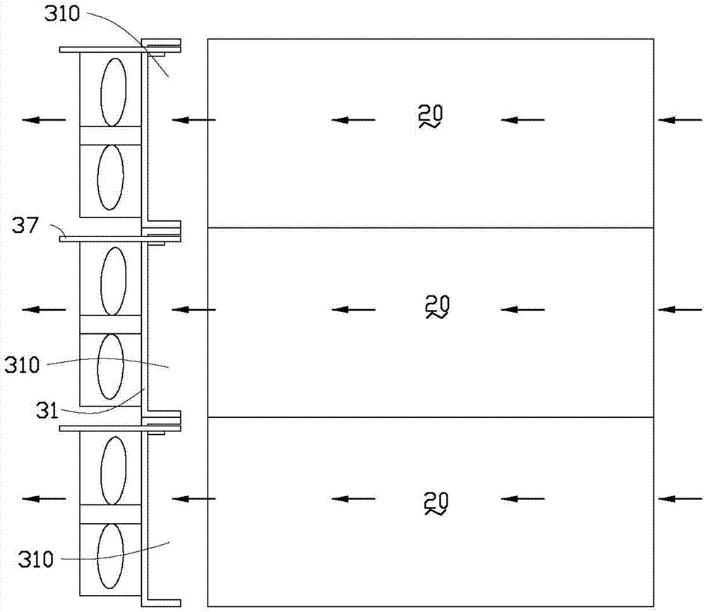
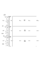
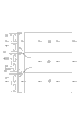
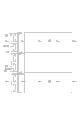
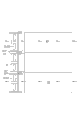
A rack-type server system, comprising a rack, several servers installed in the rack, and several fan modules arranged in rows, each fan module is used to dissipate heat for one of the servers or several adjacent servers, each fan The module includes a mounting frame fixed on the cabinet, a number of fans fixed on the outside of the mounting frame, a windshield and a controller for controlling the operation of these fans. An air duct is formed on the inside of the mounting frame for The airflow generated by these fans is guided to the corresponding server. The installation frame is provided with an opening communicating with the air duct of the adjacent installation frame. Slide between to cover or reveal the opening. The cabinet type server system of the invention can effectively save electric energy and improve heat dissipation effect.
Description
| |
10 |
| |
20、20a |
| The |
30 |
| Erecting |
31 |
| The |
310 |
| |
311 |
| |
3112 |
| |
3114 |
| |
312 |
| Flanging | 3121 |
| The support portion | 3123 |
| |
313 |
| |
3132、3142 |
| Diapire | 314 |
| |
33 |
| |
35 |
| |
37 |
| |
371 |
| Grab | 3713 |
| |
372 |
Claims (8)
Priority Applications (3)
| Application Number | Priority Date | Filing Date | Title |
|---|---|---|---|
| CN201110423312.XA CN103163990B (en) | 2011-12-16 | 2011-12-16 | Cabinet-type server system |
| TW100147570A TW201328560A (en) | 2011-12-16 | 2011-12-20 | Rackable server system |
| US13/340,687 US8547694B2 (en) | 2011-12-16 | 2011-12-30 | Rack-mount server system |
Applications Claiming Priority (1)
| Application Number | Priority Date | Filing Date | Title |
|---|---|---|---|
| CN201110423312.XA CN103163990B (en) | 2011-12-16 | 2011-12-16 | Cabinet-type server system |
Publications (2)
| Publication Number | Publication Date |
|---|---|
| CN103163990A true CN103163990A (en) | 2013-06-19 |
| CN103163990B CN103163990B (en) | 2016-07-06 |
Family
ID=48587144
Family Applications (1)
| Application Number | Title | Priority Date | Filing Date |
|---|---|---|---|
| CN201110423312.XA Active CN103163990B (en) | 2011-12-16 | 2011-12-16 | Cabinet-type server system |
Country Status (3)
| Country | Link |
|---|---|
| US (1) | US8547694B2 (en) |
| CN (1) | CN103163990B (en) |
| TW (1) | TW201328560A (en) |
Cited By (6)
| Publication number | Priority date | Publication date | Assignee | Title |
|---|---|---|---|---|
| CN103596410A (en) * | 2013-11-20 | 2014-02-19 | 华为技术有限公司 | Communication board and communication device |
| CN104679174A (en) * | 2013-11-26 | 2015-06-03 | 纬创资通股份有限公司 | Electronic device with function of replacing element |
| CN104679182A (en) * | 2013-11-28 | 2015-06-03 | 英业达科技有限公司 | server |
| CN107871511A (en) * | 2016-09-23 | 2018-04-03 | 伊姆西Ip控股有限责任公司 | Manage the method and storage device of storage device |
| CN112987885A (en) * | 2021-03-02 | 2021-06-18 | 英业达科技有限公司 | Server cabinet |
| CN113490377A (en) * | 2021-07-26 | 2021-10-08 | 南昌华勤电子科技有限公司 | Card seat and server |
Families Citing this family (22)
| Publication number | Priority date | Publication date | Assignee | Title |
|---|---|---|---|---|
| CN102929358A (en) * | 2011-08-09 | 2013-02-13 | 鸿富锦精密工业(深圳)有限公司 | Server cabinet |
| CN102929375A (en) * | 2011-08-09 | 2013-02-13 | 鸿富锦精密工业(深圳)有限公司 | Server cabinet |
| CN102929359A (en) * | 2011-08-09 | 2013-02-13 | 鸿富锦精密工业(深圳)有限公司 | Server cabinet |
| CN102999116B (en) * | 2011-09-08 | 2015-06-17 | 英业达股份有限公司 | server rack |
| CA2907390C (en) * | 2013-03-15 | 2019-01-08 | Zonit Structured Solutions, Llc | Modular data center cooling |
| US10037061B1 (en) * | 2013-04-30 | 2018-07-31 | Amazon Technologies, Inc. | Multiple-stage cooling system for rack |
| CN104427814A (en) * | 2013-08-27 | 2015-03-18 | 鸿富锦精密电子(天津)有限公司 | Wire arranging device and electronic device provided with same |
| US10085363B2 (en) * | 2014-05-22 | 2018-09-25 | General Electric Company | Integrated compact impingement on extended heat surface |
| AU2015276109B2 (en) | 2014-06-17 | 2020-11-19 | Adc Czech Republic, S.R.O. | Cable distribution system |
| US9850908B2 (en) | 2015-01-27 | 2017-12-26 | International Business Machines Corporation | Variable inlet vanes |
| US9681579B2 (en) * | 2015-06-12 | 2017-06-13 | International Business Machines Corporation | Cooling system for electronic devices employing adjacent fan cages with interflow passages |
| US10231361B2 (en) * | 2015-07-30 | 2019-03-12 | Quanta Computer Inc. | Fan system management |
| US10368466B1 (en) * | 2015-10-06 | 2019-07-30 | Amazon Technologies, Inc. | Rack mountable cooling canister |
| US10321608B1 (en) * | 2015-12-14 | 2019-06-11 | Amazon Technologies, Inc. | Coordinated cooling using rack mountable cooling canisters |
| US10637220B2 (en) | 2016-01-28 | 2020-04-28 | CommScope Connectivity Belgium BVBA | Modular hybrid closure |
| CN106659073A (en) * | 2016-12-05 | 2017-05-10 | 郑州云海信息技术有限公司 | Refrigeration device of single-cabinet data center |
| KR102615769B1 (en) * | 2018-05-18 | 2023-12-20 | 삼성전자주식회사 | Memory device |
| CN113064769A (en) * | 2020-12-24 | 2021-07-02 | 泰州可以信息科技有限公司 | Large server troubleshooting system |
| CN114302611B (en) * | 2021-11-30 | 2024-01-16 | 苏州浪潮智能科技有限公司 | Cooling devices and electronic equipment |
| CN114222483B (en) * | 2021-12-20 | 2023-02-07 | 珠海格力电器股份有限公司 | Control method of electric cabinet internal fan, and device, equipment, system and robot thereof |
| US12550287B2 (en) * | 2023-05-24 | 2026-02-10 | Nanning Fulian Fugui Precision Industrial Co., Ltd. | Fan module and electronic device |
| CN117835677B (en) * | 2024-03-04 | 2024-05-10 | 山西中云智谷数据科技有限责任公司 | Heat radiation system of server equipment |
Citations (5)
| Publication number | Priority date | Publication date | Assignee | Title |
|---|---|---|---|---|
| CN101470488A (en) * | 2007-12-27 | 2009-07-01 | 鸿富锦精密工业(深圳)有限公司 | Server cabinet |
| US7800902B2 (en) * | 2007-06-04 | 2010-09-21 | Hewlett-Packard Development Company, L.P. | Air backflow prevention in an enclosure |
| CN201820165U (en) * | 2010-10-18 | 2011-05-04 | 英业达股份有限公司 | rack server |
| CN102081445A (en) * | 2009-11-26 | 2011-06-01 | 鸿富锦精密工业(深圳)有限公司 | Heat dissipation system |
| CN102087541A (en) * | 2009-12-04 | 2011-06-08 | 鸿富锦精密工业(深圳)有限公司 | Radiating device for server and fan module thereof |
Family Cites Families (14)
| Publication number | Priority date | Publication date | Assignee | Title |
|---|---|---|---|---|
| US4648007A (en) * | 1985-10-28 | 1987-03-03 | Gte Communications Systems Corporation | Cooling module for electronic equipment |
| US6042348A (en) * | 1998-05-11 | 2000-03-28 | Lucent Technologies Inc. | Protective shutter assembly for a forced air cooling system |
| DE10136457B4 (en) * | 2001-07-26 | 2005-02-03 | Rittal Gmbh & Co. Kg | Control cabinet with a cabinet door attached to the front and a rear wall designed as a cabinet door |
| TW535488B (en) * | 2002-05-29 | 2003-06-01 | Delta Electronics Inc | Flow direction control mechanism |
| US7508663B2 (en) * | 2003-12-29 | 2009-03-24 | Rackable Systems, Inc. | Computer rack cooling system with variable airflow impedance |
| US20050168942A1 (en) * | 2004-02-04 | 2005-08-04 | Steinbrecher Robin A. | Airflow gates for electronic devices |
| CN200990050Y (en) * | 2006-12-22 | 2007-12-12 | 鸿富锦精密工业(深圳)有限公司 | Air inducer |
| CN101568249A (en) * | 2008-04-22 | 2009-10-28 | 鸿富锦精密工业(深圳)有限公司 | Electronic system and wind direction limit device thereof |
| CN102073360B (en) * | 2009-11-24 | 2015-04-22 | 淮南圣丹网络工程技术有限公司 | Server rack and server thereof |
| US7952870B1 (en) * | 2010-02-02 | 2011-05-31 | Hong Fu Jin Precision Industry (Shenzhen) Co., Ltd. | Computer enclosure |
| JP2012114379A (en) * | 2010-11-26 | 2012-06-14 | Fujitsu Ltd | Air cooling mechanism |
| JP5663766B2 (en) * | 2011-03-30 | 2015-02-04 | 富士通株式会社 | Server device, control device, server rack, cooling control program, and cooling control method |
| CN102968164A (en) * | 2011-09-01 | 2013-03-13 | 鸿富锦精密工业(深圳)有限公司 | Cooling system with backflow prevention function |
| CN103002705B (en) * | 2011-09-08 | 2015-07-15 | 英业达股份有限公司 | Movable shutter device and server rack |
-
2011
- 2011-12-16 CN CN201110423312.XA patent/CN103163990B/en active Active
- 2011-12-20 TW TW100147570A patent/TW201328560A/en unknown
- 2011-12-30 US US13/340,687 patent/US8547694B2/en not_active Expired - Fee Related
Patent Citations (5)
| Publication number | Priority date | Publication date | Assignee | Title |
|---|---|---|---|---|
| US7800902B2 (en) * | 2007-06-04 | 2010-09-21 | Hewlett-Packard Development Company, L.P. | Air backflow prevention in an enclosure |
| CN101470488A (en) * | 2007-12-27 | 2009-07-01 | 鸿富锦精密工业(深圳)有限公司 | Server cabinet |
| CN102081445A (en) * | 2009-11-26 | 2011-06-01 | 鸿富锦精密工业(深圳)有限公司 | Heat dissipation system |
| CN102087541A (en) * | 2009-12-04 | 2011-06-08 | 鸿富锦精密工业(深圳)有限公司 | Radiating device for server and fan module thereof |
| CN201820165U (en) * | 2010-10-18 | 2011-05-04 | 英业达股份有限公司 | rack server |
Cited By (11)
| Publication number | Priority date | Publication date | Assignee | Title |
|---|---|---|---|---|
| CN103596410A (en) * | 2013-11-20 | 2014-02-19 | 华为技术有限公司 | Communication board and communication device |
| CN103596410B (en) * | 2013-11-20 | 2016-03-30 | 华为技术有限公司 | A kind of communication single-board and communication equipment |
| CN104679174A (en) * | 2013-11-26 | 2015-06-03 | 纬创资通股份有限公司 | Electronic device with function of replacing element |
| CN104679174B (en) * | 2013-11-26 | 2018-01-09 | 纬创资通股份有限公司 | Electronic device with function of replacing element |
| CN104679182A (en) * | 2013-11-28 | 2015-06-03 | 英业达科技有限公司 | server |
| CN104679182B (en) * | 2013-11-28 | 2018-06-01 | 英业达科技有限公司 | server |
| CN107871511A (en) * | 2016-09-23 | 2018-04-03 | 伊姆西Ip控股有限责任公司 | Manage the method and storage device of storage device |
| US10522191B2 (en) | 2016-09-23 | 2019-12-31 | EMC IP Holding Company LLC | Controlling fan speed based on hard disk assembly position |
| CN112987885A (en) * | 2021-03-02 | 2021-06-18 | 英业达科技有限公司 | Server cabinet |
| CN112987885B (en) * | 2021-03-02 | 2023-03-14 | 英业达科技有限公司 | Server cabinet |
| CN113490377A (en) * | 2021-07-26 | 2021-10-08 | 南昌华勤电子科技有限公司 | Card seat and server |
Also Published As
| Publication number | Publication date |
|---|---|
| US20130155608A1 (en) | 2013-06-20 |
| US8547694B2 (en) | 2013-10-01 |
| CN103163990B (en) | 2016-07-06 |
| TW201328560A (en) | 2013-07-01 |
Similar Documents
| Publication | Publication Date | Title |
|---|---|---|
| CN103163990B (en) | Cabinet-type server system | |
| EP3089569B1 (en) | Subrack and terminal | |
| CN202374619U (en) | Novel heat-exchange communication cabinet | |
| CN103490595A (en) | Converter cabinet | |
| US11044831B2 (en) | Electrical enclosure arrangement comprising an electrical enclosure line and a cooling device connected into the line | |
| CN103249279A (en) | Electric box assembly and multi-connected air conditioning unit using same | |
| CN207340352U (en) | A kind of air-conditioning electric control box | |
| CN205407046U (en) | Photovoltaic prepackage type cooling system of transformer substation | |
| TW201408179A (en) | Air guiding member and electronic device having the same | |
| US11116111B2 (en) | Method and arrangement for air-conditioning a cold aisle | |
| CN103164003A (en) | Electronic device heat dissipating system | |
| CN102467201A (en) | Cooling circulation system of server | |
| CN203633045U (en) | Novel forced air cooling heat radiation cabinet | |
| CN203554257U (en) | Current transformer cabinet | |
| CN106411110A (en) | Heat radiation controllable frequency converter | |
| CN211233118U (en) | Heat radiation structure for compressor cavity and electric control box of outdoor unit of air conditioner | |
| CN201774472U (en) | Inverter power unit | |
| CN102402256A (en) | server chassis | |
| CN105718006A (en) | Orthogonal heat dissipation case | |
| CN205429113U (en) | Battery box cooling system | |
| CN209962840U (en) | Novel cooling structure of dry-type transformer | |
| CN202836287U (en) | Heat pipe exchanger component | |
| CN217435463U (en) | Mounting structure and have its vehicle | |
| CN216775351U (en) | Heat radiation structure and have its electrical equipment | |
| CN215929866U (en) | Dehumidification device and air conditioner with same |
Legal Events
| Date | Code | Title | Description |
|---|---|---|---|
| C06 | Publication | ||
| PB01 | Publication | ||
| C10 | Entry into substantive examination | ||
| SE01 | Entry into force of request for substantive examination | ||
| C41 | Transfer of patent application or patent right or utility model | ||
| TA01 | Transfer of patent application right |
Effective date of registration: 20160126 Address after: 201424 Shanghai city Fengxian District Tuo Village barracks Lin Zhen No. 598 building ninth room 111 Applicant after: Shanghai Lirui Network Technology Co.,Ltd. Address before: 518109 Guangdong province Shenzhen city Longhua District Dragon Road No. 83 wing group building 11 floor Applicant before: SCIENBIZIP CONSULTING (SHEN ZHEN) Co.,Ltd. Effective date of registration: 20160126 Address after: 518109 Guangdong province Shenzhen city Longhua District Dragon Road No. 83 wing group building 11 floor Applicant after: SCIENBIZIP CONSULTING (SHEN ZHEN) Co.,Ltd. Address before: 518109 Guangdong city of Shenzhen province Baoan District Longhua Town Industrial Zone tabulaeformis tenth East Ring Road No. 2 two Applicant before: HONG FU JIN PRECISION INDUSTRY (SHENZHEN) Co.,Ltd. Applicant before: HON HAI PRECISION INDUSTRY Co.,Ltd. |
|
| C41 | Transfer of patent application or patent right or utility model | ||
| TA01 | Transfer of patent application right |
Effective date of registration: 20160516 Address after: Tianhe District Tong East Road Guangzhou city Guangdong province 510665 B-101 No. 5, room B-118 Applicant after: Xiao Baiyu Address before: 201424 Shanghai city Fengxian District Tuo Village barracks Lin Zhen No. 598 building ninth room 111 Applicant before: Shanghai Lirui Network Technology Co.,Ltd. |
|
| C41 | Transfer of patent application or patent right or utility model | ||
| CB03 | Change of inventor or designer information |
Inventor after: Wei Ran Inventor after: Liu Yinlei Inventor after: Liu Lu Inventor after: Liu Zongjie Inventor after: Zhu Haipeng Inventor after: Zhao Lei Inventor after: Zhou Ke Inventor after: Kou Jun Inventor after: Kong Ping Inventor after: Guan Ti Inventor after: Ma Qiang Inventor after: Qin Kun Inventor before: Tang Xianxiu |
|
| COR | Change of bibliographic data | ||
| TA01 | Transfer of patent application right |
Effective date of registration: 20160606 Address after: 100000 Xicheng District West Chang'an Avenue, No. 86, Beijing Applicant after: State Grid Corporation of China Applicant after: Jining Power Supply Company Address before: Tianhe District Tong East Road Guangzhou city Guangdong province 510665 B-101 No. 5, room B-118 Applicant before: Xiao Baiyu |
|
| C14 | Grant of patent or utility model | ||
| GR01 | Patent grant |