CN103101785A - Elastic supporting winding machine - Google Patents
Elastic supporting winding machine Download PDFInfo
- Publication number
- CN103101785A CN103101785A CN 201110358914 CN201110358914A CN103101785A CN 103101785 A CN103101785 A CN 103101785A CN 201110358914 CN201110358914 CN 201110358914 CN 201110358914 A CN201110358914 A CN 201110358914A CN 103101785 A CN103101785 A CN 103101785A
- Authority
- CN
- China
- Prior art keywords
- roll shaft
- wheel
- supporting
- support
- pole
- Prior art date
- Legal status (The legal status is an assumption and is not a legal conclusion. Google has not performed a legal analysis and makes no representation as to the accuracy of the status listed.)
- Pending
Links
- 238000004804 winding Methods 0.000 title abstract description 9
- 238000007664 blowing Methods 0.000 claims description 7
- 238000007599 discharging Methods 0.000 abstract 2
- 230000000694 effects Effects 0.000 description 2
- 230000009286 beneficial effect Effects 0.000 description 1
- 230000007812 deficiency Effects 0.000 description 1
- 238000005516 engineering process Methods 0.000 description 1
Images
Landscapes
- Winding Of Webs (AREA)
Abstract
The invention relates to the technical field of winding machines, in particular to an elastic supporting winding machine. The elastic supporting winding machine comprises a support, a discharging wheel, a guiding wheel, a receiving wheel and a roll shaft, wherein the discharging wheel, the guiding wheel and the roll shaft are successively arranged on the support, the receiving wheel is placed on the roll shaft, the roll shaft is arranged on supporting rods, and a spring is connected between two supporting rods. The roll shaft is arranged on the supporting rods which can rotate a certain angle to regulate supporting radiuses, tension is kept under action of the spring, after the diameter of a winding core shaft becomes large, the weight becomes large, the supporting rods are stretched, a supporting angle becomes large, and therefore supporting force is provided continuously and stably.
Description
Technical field
The present invention relates to the winding apparatus technical field, especially a kind of resilient mounting up-coiler.
Background technology
at present, taking in of flexible platelet, arrange, deposit and all adopt up-coiler to be rolled into tubular, existing up-coiler mainly contains two kinds, a kind of is to adopt the coiling mandrel directly to drive wind2, another kind of is that winding apparatus is got in friction, it is by one or two friction roller friction drive winding core axles rotations that superficial velocity is constant that winding apparatus is got in existing friction, to be made roll by roll of material, although designs simplification, it is convenient to control, but, the position of two friction rollers is fixed, the support scope is constant, after the diameter of coiling mandrel becomes greatly, can't do corresponding adjustment, cause the strong point to diminish, stability reduces.
Summary of the invention
Get the volume up-coiler to support scope constant in order to overcome existing friction roller, very flexible, the deficiency that stability is low the invention provides a kind of resilient mounting up-coiler.
The technical solution adopted for the present invention to solve the technical problems is: a kind of resilient mounting up-coiler, comprise support, blowing wheel, material-guiding wheel, rewinding wheel and roll shaft, blowing wheel, material-guiding wheel and roll shaft are arranged in order rack-mount, the rewinding wheel is placed on roll shaft, roll shaft is arranged on pole, is connected with spring between two poles.
According to another embodiment of the invention, comprise that further pole is connected on a base, base is fixed on support.
According to another embodiment of the invention, comprise that further base two ends are provided with the groove of " V " shape.
According to another embodiment of the invention, comprise that further the upper end of pole is connected with roll shaft, the lower end is inserted in groove, rotarys connection with base by bearing pin.
The invention has the beneficial effects as follows, roll shaft is arranged on pole, pole can be done the rotation of certain angle, and regulate and support radius, and under the effect of spring, keep tension force, after the diameter of take-up pulley became greatly, weight also became greatly, and pole is strutted, support angle becomes greatly thereupon, thereby continual and steady bearing force is provided.
Description of drawings
The present invention is further described below in conjunction with drawings and Examples.
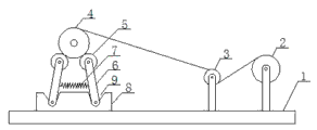
Fig. 1 is structural representation of the present invention.
1. supports in figure, 2. blowing wheel, 3. material-guiding wheel, 4. rewinding wheel, 5. roll shaft, 6. pole, 7. spring, 8. base, 9. groove.
The specific embodiment
Structural representation of the present invention as Fig. 1, a kind of resilient mounting up-coiler, comprise support 1, blowing wheel 2, material-guiding wheel 3, rewinding wheel 4 and roll shaft 5, blowing wheel 2, material-guiding wheel 3 and roll shaft 5 are arranged in order and are arranged on support 1, rewinding wheel 4 is placed on roll shaft 5, roll shaft 5 is arranged on pole 6, is connected with spring 7 between two poles 6.Pole 6 is connected on a base 8, and base 8 is fixed on support 1.Base 8 two ends are provided with the groove 9 of " V " shape.The upper end of pole 6 is connected with roll shaft 5, and the lower end is inserted in groove 9, rotarys connection with base 8 by bearing pin.
Roll shaft 5 is arranged on pole 6, and pole 6 can be done the rotation of certain angle, and regulate and support radius, and under the effect of spring 7, keep tension force, after the diameter of take-up pulley 4 became greatly, it is large that weight also becomes, pole 6 is strutted, and support angle becomes greatly thereupon, thereby continual and steady bearing force is provided.
Claims (4)
1. resilient mounting up-coiler, comprise support (1), blowing wheel (2), material-guiding wheel (3), rewinding wheel (4) and roll shaft (5), blowing wheel (2), material-guiding wheel (3) and roll shaft (5) are arranged in order and are arranged on support (1), rewinding wheel (4) is placed on roll shaft (5), it is characterized in that, roll shaft (5) is arranged on pole (6), is connected with spring (7) between two poles (6).
2. resilient mounting up-coiler according to claim 1, is characterized in that, pole (6) is connected on a base (8), and base (8) is fixed on support (1).
3. resilient mounting up-coiler according to claim 2, is characterized in that, base (8) two ends are provided with the groove (9) of " V " shape.
4. resilient mounting up-coiler according to claim 1, is characterized in that, the upper end of pole (6) is connected with roll shaft (5), and the lower end is inserted in groove (9), rotarys connection with base (8) by bearing pin.
Priority Applications (1)
| Application Number | Priority Date | Filing Date | Title |
|---|---|---|---|
| CN 201110358914 CN103101785A (en) | 2011-11-14 | 2011-11-14 | Elastic supporting winding machine |
Applications Claiming Priority (1)
| Application Number | Priority Date | Filing Date | Title |
|---|---|---|---|
| CN 201110358914 CN103101785A (en) | 2011-11-14 | 2011-11-14 | Elastic supporting winding machine |
Publications (1)
| Publication Number | Publication Date |
|---|---|
| CN103101785A true CN103101785A (en) | 2013-05-15 |
Family
ID=48310040
Family Applications (1)
| Application Number | Title | Priority Date | Filing Date |
|---|---|---|---|
| CN 201110358914 Pending CN103101785A (en) | 2011-11-14 | 2011-11-14 | Elastic supporting winding machine |
Country Status (1)
| Country | Link |
|---|---|
| CN (1) | CN103101785A (en) |
Cited By (4)
| Publication number | Priority date | Publication date | Assignee | Title |
|---|---|---|---|---|
| CN105081660A (en) * | 2015-08-27 | 2015-11-25 | 重庆万斯金属特种成形有限公司 | Automobile silencer peripheral surface welding machine |
| CN106694561A (en) * | 2016-12-19 | 2017-05-24 | 苏州唐氏机械制造有限公司 | Controllable compression roller mechanism |
| CN107347511A (en) * | 2017-08-10 | 2017-11-17 | 贵州六合门业有限公司 | A kind of greenhouse roller device for potyvirus production |
| CN108545509A (en) * | 2018-05-17 | 2018-09-18 | 来安县义坤农业发展有限公司 | A kind of quick reel-off gear of tatami rush volume |
-
2011
- 2011-11-14 CN CN 201110358914 patent/CN103101785A/en active Pending
Cited By (4)
| Publication number | Priority date | Publication date | Assignee | Title |
|---|---|---|---|---|
| CN105081660A (en) * | 2015-08-27 | 2015-11-25 | 重庆万斯金属特种成形有限公司 | Automobile silencer peripheral surface welding machine |
| CN106694561A (en) * | 2016-12-19 | 2017-05-24 | 苏州唐氏机械制造有限公司 | Controllable compression roller mechanism |
| CN107347511A (en) * | 2017-08-10 | 2017-11-17 | 贵州六合门业有限公司 | A kind of greenhouse roller device for potyvirus production |
| CN108545509A (en) * | 2018-05-17 | 2018-09-18 | 来安县义坤农业发展有限公司 | A kind of quick reel-off gear of tatami rush volume |
Similar Documents
| Publication | Publication Date | Title |
|---|---|---|
| CN205709033U (en) | A kind of Novel plastic-film wrap-up | |
| CN202369154U (en) | Elastic supporting winder | |
| CN202214597U (en) | Special bobbin winder for sewing machine | |
| CN203382322U (en) | Radius-adjustable double-side wire hanger | |
| CN103101786A (en) | Automatic adjustment winder | |
| CN102688910A (en) | Rolling device | |
| CN105413100A (en) | Fitness equipment and pull rope device | |
| CN208561250U (en) | A kind of cable winding device | |
| CN217074894U (en) | PVC tubular product winding membrane self-adaptation winding mechanism | |
| CN103101784A (en) | Multistage adjustment coiler | |
| CN202369153U (en) | Multilevel adjustment winding machine | |
| CN110937460A (en) | Linear material winding device | |
| CN102303793B (en) | Winding tensioner | |
| CN206505828U (en) | A kind of coil-winding equipment | |
| CN101700841B (en) | Active carbon fiber filter winding device | |
| CN210029454U (en) | Tension unreeling device for reel embossing machine | |
| CN113192705B (en) | Polyester tape winding equipment for cable processing | |
| CN213386952U (en) | Tensioning and winding device of polyimide film splitting machine | |
| CN202687592U (en) | Winding tension automatic control device | |
| CN206051154U (en) | Spinning Winder | |
| CN218261199U (en) | Cutting device | |
| CN203294848U (en) | Steady winding machine | |
| CN218538620U (en) | Novel fire-resistant mica tape rolling device | |
| CN205508613U (en) | Transformer coil's winding device | |
| CN202379501U (en) | Cloth roll sorting mechanism for glass fiber cloth shearing machine |
Legal Events
| Date | Code | Title | Description |
|---|---|---|---|
| C06 | Publication | ||
| PB01 | Publication | ||
| C02 | Deemed withdrawal of patent application after publication (patent law 2001) | ||
| WD01 | Invention patent application deemed withdrawn after publication |
Application publication date: 20130515 |