CN103081991B - Continuous type infrared corncob drying machine - Google Patents
Continuous type infrared corncob drying machine Download PDFInfo
- Publication number
- CN103081991B CN103081991B CN2013100568477A CN201310056847A CN103081991B CN 103081991 B CN103081991 B CN 103081991B CN 2013100568477 A CN2013100568477 A CN 2013100568477A CN 201310056847 A CN201310056847 A CN 201310056847A CN 103081991 B CN103081991 B CN 103081991B
- Authority
- CN
- China
- Prior art keywords
- sprocket
- chain
- conveying device
- box
- box body
- Prior art date
- Legal status (The legal status is an assumption and is not a legal conclusion. Google has not performed a legal analysis and makes no representation as to the accuracy of the status listed.)
- Expired - Fee Related
Links
Images


Classifications
-
- Y—GENERAL TAGGING OF NEW TECHNOLOGICAL DEVELOPMENTS; GENERAL TAGGING OF CROSS-SECTIONAL TECHNOLOGIES SPANNING OVER SEVERAL SECTIONS OF THE IPC; TECHNICAL SUBJECTS COVERED BY FORMER USPC CROSS-REFERENCE ART COLLECTIONS [XRACs] AND DIGESTS
- Y02—TECHNOLOGIES OR APPLICATIONS FOR MITIGATION OR ADAPTATION AGAINST CLIMATE CHANGE
- Y02P—CLIMATE CHANGE MITIGATION TECHNOLOGIES IN THE PRODUCTION OR PROCESSING OF GOODS
- Y02P60/00—Technologies relating to agriculture, livestock or agroalimentary industries
- Y02P60/80—Food processing, e.g. use of renewable energies or variable speed drives in handling, conveying or stacking
- Y02P60/85—Food storage or conservation, e.g. cooling or drying
Landscapes
- Drying Of Solid Materials (AREA)
Abstract
本发明提供一种连续式红外玉米穗干燥机,其特征在于:箱体内设有多条由传动装置驱动运转的输送装置,Ⅰ型和Ⅱ型两种长度不同的拨料杆相间地固定在同一输送装置的两条链条之间,每条输送装置对应于链条的上、下两段水平段分别设置有托料板,托料板末端下方设有导料槽,托料板上方设有辐射装置,辐射装置的辐射架吊装于箱体上,单方向向下辐射红外线的红外辐射元件两端安装在辐射架上,箱体顶部设有进料口,底部设有出料口。本发明传热效率高、能耗低、干燥均匀性好。
The invention provides a continuous infrared corn cob dryer, which is characterized in that: a plurality of conveying devices driven by a transmission device are arranged in the box, and two types of material levers with different lengths, type I and type II, are alternately fixed on the Between the two chains of the same conveying device, each conveying device is provided with a supporting plate corresponding to the upper and lower horizontal sections of the chain, a material guide groove is provided under the end of the supporting plate, and a radial The radiation frame of the radiation device is hoisted on the box body, and the two ends of the infrared radiation element that radiate infrared rays downward in one direction are installed on the radiation frame. The top of the box body is provided with a material inlet, and the bottom is provided with a material outlet. The invention has high heat transfer efficiency, low energy consumption and good drying uniformity.
Description
技术领域 technical field
本发明提供一种连续式红外玉米穗干燥机,主要用于对刚从玉米秸秆上采摘后、含水率较高的湿玉米穗进行脱水干燥。 The invention provides a continuous infrared corn cob dryer, which is mainly used for dehydrating and drying wet corn cobs with high moisture content just after picking from corn stalks.
背景技术 Background technique
中国是农业大国,特别是山东、河南及东北等地区是玉米等主要粮食产区。随着养殖业的发展、饲料的需求量增加,玉米的种植面积逐步扩大,产量逐年提高。玉米收获水分一般为25%—35%,如果没有良好的玉米干燥设备,将会因水分过大、发霉而导致大量损失。因此,农民对玉米干燥机的需求愈加迫切,开发研制降水幅度高、干燥均匀性好、品质优良的玉米干燥机,对推动玉米产业的发展有着重要的意义。 China is a large agricultural country, especially in Shandong, Henan and Northeast China, which are the major food producing areas such as corn. With the development of the breeding industry and the increase in the demand for feed, the planting area of corn has gradually expanded, and the output has increased year by year. The harvest moisture of corn is generally 25%-35%. If there is no good corn drying equipment, it will cause a lot of loss due to excessive moisture and mold. Therefore, farmers' demand for corn dryers is becoming more and more urgent. It is of great significance to develop corn dryers with high precipitation, good drying uniformity and high quality to promote the development of corn industry.
目前,市场上已有一些仓式和滚筒式玉米烘干机,这些设备是利用机械设备将玉米籽粒水分降低到安全包装和储藏的范围之内,以达到长期保存之目的,这对减少玉米的产后损失,确保玉米的丰产丰收具有重要意义。 At present, there are some warehouse-type and drum-type corn dryers on the market. These equipment use mechanical equipment to reduce the moisture content of corn kernels to the range of safe packaging and storage, so as to achieve the purpose of long-term preservation. Post-harvest loss is of great significance to ensure the high yield and good harvest of maize.
但是,现有的各种玉米干燥设备都是用于对玉米籽粒进行脱水干燥的。而玉米穗刚刚从田间采摘后含水率较高,如果采用先脱粒、后干燥的工艺方案,将因玉米穗的含水率较大而导致脱粒后籽粒的破碎率较高,无法满足实际生产需要。因此,我们研制了一种连续式玉米穗干燥机。该机能够连续地将湿玉米穗进行干燥,且生产率比较高,因此申请了国家发明专利,申请号为:201310046462.2。利用干燥后期含湿量较大、温度比较低的热风对湿玉米穗进行预热时,改为热风与玉米穗互不接触这种方式后,又申请了国家发明专利,申请号为:201310049368.2;利用水气加热器加热后的热水对预热后、但预热温度尚未达到要求的湿玉米穗再次进行预热后,又申请了国家发明专利,申请号为:201310050556.7。上述专利所涉及的玉米穗干燥设备已能够对湿玉米穗进行正常干燥了,但经干燥后从出料口流出的玉米穗温度太高,既不便于包装,又浪费能源;改为待玉米穗的含水率达到要求后,使其在最下面的输送装置下段槽形物料通道内与常温空气进行热交换后,又申请了国家发明专利,申请号为:201310052038.9。但是,上述专利涉及的玉米穗干燥机均采用热风对流干燥,热风温度一般都比较高,且在常压下进行干燥,因此有时会导致玉米粒爆腰;若降低热风温度,则传热速度减慢,干燥时间较长。另外,热风干燥能耗相对较高。 However, various existing corn drying equipment are all used for dehydrating and drying corn grains. However, corn ears have a high moisture content just after they are picked from the field. If the process of threshing first and then drying is adopted, the high moisture content of corn ears will lead to a high rate of broken grains after threshing, which cannot meet actual production needs. Therefore, we have developed a continuous corn ear dryer. This machine can continuously dry wet ears of corn, and has relatively high productivity, so it has applied for a national invention patent with the application number: 201310046462.2. When using the hot air with high moisture content and relatively low temperature in the late drying stage to preheat the wet corn ears, after changing the way that the hot air and corn ears do not contact each other, we applied for a national invention patent, and the application number is: 201310049368.2; After using the hot water heated by the water-air heater to preheat the wet corn ears that have been preheated but the preheating temperature has not yet reached the required level, the company has applied for a national invention patent with the application number: 201310050556.7. The ear of corn drying equipment involved in the above patent has been able to dry the ear of corn normally, but the temperature of the ear of corn flowing out from the discharge port after drying is too high, which is not convenient for packaging and wastes energy; After the moisture content reaches the requirement, make it heat exchange with normal temperature air in the lower channel of the conveying device, and then apply for a national invention patent, the application number is: 201310052038.9. However, the cob dryers involved in the above-mentioned patents all adopt hot air convection drying, and the temperature of the hot air is generally relatively high, and the drying is carried out under normal pressure, so sometimes the corn kernels will burst; if the temperature of the hot air is lowered, the heat transfer rate will decrease. Slow, longer drying time. In addition, the energy consumption of hot air drying is relatively high.
综观玉米干燥行业现状,急需一种干燥速度快、传热效率高、能耗低、干燥均匀,且干粮品质好的玉米穗干燥设备。 Looking at the current situation of the corn drying industry, there is an urgent need for a corn ear drying equipment with fast drying speed, high heat transfer efficiency, low energy consumption, uniform drying, and good dry food quality.
发明内容 Contents of the invention
本发明的目的是提供一种能克服现有玉米干燥设备所存在的问题,传热效率高、能耗低、干燥均匀性好,且干粮品质好的连续式红外玉米穗干燥设备。 The purpose of the present invention is to provide a continuous infrared corn cob drying equipment that can overcome the problems existing in the existing corn drying equipment, has high heat transfer efficiency, low energy consumption, good drying uniformity, and good dry food quality.
其技术方案为:包括箱体、传动装置、输送装置和辐射装置,长方形箱体顶部一端设有进料口,同一端在箱体底部设有出料口,箱体内沿长度方向设有多条输送装置,输送装置包括轴、链轮、链条和拨料杆,同一输送装置两条轴的轴线垂直于箱体的长度方向、且水平布置在箱体沿长度方向的两端,轴两端均支承于箱体立壁上,安装在箱体顶部远离进料口一端的传动装置,通过各输送装置位于传动装置下方的轴穿过箱体立壁后的伸出端逐级驱动输送装置运转,每条轴两端靠近箱体内壁处各安装有两个链轮,每条输送装置的两条轴靠近箱体同一侧内壁处的两个链轮上分别挂有一条链条,其特征在于:Ⅰ型和Ⅱ型两种长方形环状拨料杆的结构形状、宽度、厚度及环的壁厚完全相同,而长度不同、即拨料杆与长度方向相垂直的两条短边外表面之间的距离不同,Ⅰ型拨料杆的长度等于同一输送装置的两条链条之间最近的内链节外表面之间的距离,Ⅱ型拨料杆的长度等于同一输送装置的两条链条之间最近的外链节外表面之间的距离,Ⅰ型拨料杆的两条短边外表面中部通过螺钉固定在同一输送装置的两条链条内侧的内链节外表面沿着长度方向的中线处,且Ⅰ型拨料杆的短边与链条的内链节垂直,Ⅱ型拨料杆的两条短边外表面中部通过螺钉固定在同一输送装置的两条链条内侧的外链节外表面沿着长度方向的中线处,且Ⅱ型拨料杆的短边与链条的外链节垂直,相邻两拨料杆内侧表面之间的距离、即“链条的节距-拨料杆的厚度”大于玉米穗的直径,每条输送装置的4个链轮之间对应于链条的上、下两段水平段分别设置有托料板,且上、下两片托料板的上平面分别位于与4个链轮的分度圆同时相切的上、下两个平面内,托料板宽度小于同一输送装置两条链条的销轴内端面之间的距离,在进料口下方的各链轮处,沿着链条水平段的移动方向,位于链轮上方的托料板起始于链轮的分度圆远离该链轮所在端箱体立壁的象限点与链轮轴线之间的上方,位于链轮下方的托料板终止于链轮的分度圆远离该链轮所在端箱体立壁的象限点、且远离该链轮轴线一侧的下方,对应于托料板末端的下方、两个链轮之间设置有导料槽,位于箱体最下面链轮处的导料槽即为出料口,进料口对应于最上层输送装置上方托料板的起始端,在传动装置下方的各链轮处,沿着链条水平段的移动方向,位于链轮上方的托料板终止于链轮的分度圆远离该链轮所在端箱体立壁的象限点、且远离该链轮轴线一侧的上方,对应于托料板末端的下方、两个链轮之间设置有导料槽,位于链轮下方的托料板起始于链轮的分度圆远离该链轮所在端箱体立壁的象限点下方,位于各托料板上方的辐射装置包括辐射架和只能单方向辐射红外线的红外辐射元件,辐射架吊装于箱体上、且高度可调,单方向朝着托料板向下辐射红外线的各红外辐射元件两端安装在辐射架上。 Its technical scheme is as follows: including the box body, transmission device, conveying device and radiation device, one end of the top of the rectangular box body is provided with a material inlet, and the same end is provided with a discharge port at the bottom of the box body, and the box body is provided with multiple strips along the length direction. Conveying device, the conveying device includes a shaft, a sprocket, a chain and a material lever. The axes of the two shafts of the same conveying device are perpendicular to the length direction of the box body and are arranged horizontally at both ends of the box body along the length direction. Both ends of the shaft are Supported on the vertical wall of the box body, the transmission device installed on the top of the box body away from the feed inlet drives the conveying device to run step by step through the shaft of each conveying device located below the transmission device through the protruding end of the vertical wall of the box body. There are two sprockets installed at both ends of the shaft close to the inner wall of the box, and a chain is hung on the two sprockets at the two shafts of each conveying device close to the inner wall of the same side of the box. It is characterized in that: Type I and The structural shape, width, thickness and ring wall thickness of the two types of rectangular ring-shaped push rods of type II are exactly the same, but the length is different, that is, the distance between the two short sides of the push rod and the length direction is different. , the length of type I driving rod is equal to the distance between the outer surfaces of the nearest inner link between two chains of the same conveying device, and the length of type II driving rod is equal to the distance between the nearest outer surfaces of two chains of the same conveying device The distance between the outer surfaces of the chain links, the middle part of the outer surfaces of the two short sides of the type I driving rod is fixed by screws on the outer surface of the inner chain link on the inner side of the two chains of the same conveying device along the midline of the length direction, and I The short side of the type material lever is perpendicular to the inner chain link of the chain, and the middle part of the outer surface of the two short sides of the type II material lever is fixed to the outer surface of the outer link inside the two chains of the same conveying device by screws along the length direction. and the short side of the type II driving rod is perpendicular to the outer link of the chain, the distance between the inner surfaces of two adjacent driving rods, that is, the "chain pitch - the thickness of the driving rod" is greater than the ear of corn The diameter of the 4 sprockets of each conveying device is respectively provided with supporting plates corresponding to the upper and lower horizontal sections of the chain, and the upper planes of the upper and lower supporting plates are respectively located in the same position as the 4 chains In the upper and lower planes where the indexing circle of the wheel is tangent at the same time, the width of the supporting plate is smaller than the distance between the inner end faces of the pin shafts of the two chains of the same conveying device. According to the moving direction of the horizontal section of the chain, the supporting plate located above the sprocket starts from the upper part between the quadrant point of the vertical wall of the end box where the sprocket is located and the axis of the sprocket, and is located below the sprocket. The support plate of the sprocket terminates at the quadrant point of the sprocket’s indexing circle away from the vertical wall of the end box where the sprocket is located and away from the side of the sprocket axis, corresponding to the bottom of the end of the support plate and between the two sprockets. There is a material guide groove between them, the material guide groove at the bottom sprocket of the box is the discharge port, the feed port corresponds to the starting end of the support plate above the uppermost conveying device, and the sprockets below the transmission device , along the moving direction of the horizontal section of the chain, the supporting plate above the sprocket ends at the quadrant of the sprocket index circle away from the vertical wall of the end box where the sprocket is located, and above the side away from the axis of the sprocket , corresponding to the bottom of the end of the supporting plate, there is a material guide groove between the two sprockets, and the supporting plate under the sprocket The indexing circle starting from the sprocket is far away from the quadrant of the vertical wall of the end box where the sprocket is located. The radiation device above each supporting plate includes a radiation frame and an infrared radiation element that can only radiate infrared rays in one direction. The radiation frame is hoisted The two ends of each infrared radiating element, which are on the box body and can be adjusted in height and radiate infrared rays downward toward the supporting plate in one direction, are installed on the radiation frame.
所述的连续式红外玉米穗干燥机,箱体上设有保温层。 In the continuous infrared corn cob dryer, the box body is provided with an insulating layer.
本发明在现有各专利技术的基础上,长方形箱体顶部一端设有进料口,同一端在箱体底部设有出料口。箱体内沿长度方向设有多条输送装置,同一输送装置的两条轴水平布置在箱体沿长度方向的两端,两条轴两端均支承在箱体的立壁上,且轴的轴线垂直于箱体的长度方向;安装在箱体顶部远离进料口一端的传动装置,通过各输送装置位于传动装置下方的轴穿过箱体立壁后的伸出端逐级驱动输送装置运转;每条轴两端靠近箱体内壁处各安装有两个链轮,每条输送装置的两条轴靠近箱体同一侧内壁处的两个链轮上分别挂有一条链条。Ⅰ型和Ⅱ型两种长方形环状拨料杆除长度不同、即拨料杆与长度方向相垂直的两条短边外表面之间的距离不同之外,拨料杆的结构形状、宽度、厚度及环的壁厚完全相同;Ⅰ型拨料杆的长度等于同一输送装置的两条链条之间最近的内链节外表面之间的距离,Ⅱ型拨料杆的长度等于同一输送装置的两条链条之间最近的外链节外表面之间的距离。Ⅰ型拨料杆的两条短边外表面中部通过螺钉固定在同一输送装置的两条链条内侧的内链节外表面沿着长度方向的中线处,且Ⅰ型拨料杆的短边与链条的内链节垂直;Ⅱ型拨料杆的两条短边外表面中部通过螺钉固定在同一输送装置的两条链条内侧的外链节外表面沿着长度方向的中线处,且Ⅱ型拨料杆的短边与链条的外链节垂直;相邻两拨料杆内侧表面之间的距离、即“链条的节距-拨料杆的厚度”大于玉米穗的直径。每条输送装置的4个链轮之间对应于链条的上、下两段水平段分别设置有托料板,且上、下两片托料板的上平面分别位于与4个链轮的分度圆同时相切的上、下两个平面内;托料板宽度小于同一输送装置两条链条的销轴内端面之间的距离。在进料口下方的各链轮处,沿着链条水平段的移动方向,位于链轮上方的托料板起始于链轮的分度圆远离该链轮所在端箱体立壁的象限点与链轮轴线之间的上方;位于链轮下方的托料板终止于链轮的分度圆远离该链轮所在端箱体立壁的象限点、且远离该链轮轴线一侧的下方;对应于托料板末端的下方、两个链轮之间设置有导料槽,位于箱体最下面链轮处的导料槽即为出料口;位于最上层输送装置上方的托料板起始端的上方、即箱体顶部的即为进料口。在传动装置下方的各链轮处,沿着链条水平段的移动方向,位于链轮上方的托料板终止于链轮的分度圆远离该链轮所在端箱体立壁的象限点、且远离该链轮轴线一侧的上方,对应于托料板末端的下方、两个链轮之间设置有导料槽;位于链轮下方的托料板起始于链轮的分度圆远离该链轮所在端箱体立壁的象限点下方。位于各托料板上方的辐射装置高度可调的辐射架吊装于箱体上,单方向朝着托料板向下辐射红外线的各红外辐射元件两端安装在辐射架上。 The present invention is based on the existing patented technologies. One end of the top of the rectangular box body is provided with a material inlet, and the same end is provided with a material outlet at the bottom of the box body. There are multiple conveying devices along the length direction in the box. The two shafts of the same conveying device are arranged horizontally at both ends of the box along the length direction. Both ends of the two shafts are supported on the vertical wall of the box, and the axis of the shaft is vertical. In the length direction of the box body; the transmission device installed on the top of the box body away from the feed inlet, drives the conveying device to run step by step through the extension end of the shaft of each conveying device located below the transmission device after passing through the vertical wall of the box body; each Two sprockets are respectively installed near the inner wall of the box at the two ends of the shaft, and a chain is respectively hung on the two sprockets near the inner wall of the same side of the box on the two shafts of each conveying device. In addition to the different lengths of the two types of rectangular ring-shaped push rods of type I and type II, that is, the distance between the outer surfaces of the two short sides perpendicular to the length direction of the push rod is different, the structural shape, width, The thickness and the wall thickness of the ring are exactly the same; the length of the type I driving rod is equal to the distance between the outer surfaces of the nearest inner chain link between the two chains of the same conveying device, and the length of the type II driving rod is equal to that of the same conveying device The distance between the outer surfaces of the nearest outer links between two chains. The middle part of the outer surface of the two short sides of the type I driving rod is fixed by screws on the outer surface of the inner chain link inside the two chains of the same conveying device along the midline along the length direction, and the short side of the type I driving rod is in line with the chain The inner link of the inner chain link is vertical; the middle part of the outer surface of the two short sides of the type II driving rod is fixed to the center line of the outer surface of the outer chain link inside the two chains of the same conveying device along the length direction by screws, and the type II driving rod The short side of the rod is perpendicular to the outer chain link of the chain; the distance between the inner surfaces of two adjacent driving rods, that is, "the pitch of the chain - the thickness of the driving rod" is greater than the diameter of the ear of corn. Between the 4 sprockets of each conveying device, there are supporting plates corresponding to the upper and lower horizontal sections of the chain, and the upper planes of the upper and lower supporting plates are respectively located at the points of the 4 sprockets. The upper and lower planes where the degree circle is tangent at the same time; the width of the support plate is smaller than the distance between the inner end faces of the pin shafts of the two chains of the same conveying device. At each sprocket below the feed inlet, along the moving direction of the horizontal section of the chain, the supporting plate above the sprocket starts from the quadrant point of the vertical wall of the box at the end where the sprocket is located and the indexing circle of the sprocket. Above between the axes of the sprockets; the support plate located below the sprockets terminates at the quadrant of the sprocket’s index circle away from the vertical wall of the end box where the sprocket is located, and below the side away from the axis of the sprocket; corresponding to Below the end of the support plate, there is a material guide groove between the two sprockets. The material guide groove at the bottom sprocket of the box is the discharge port; The top, that is, the top of the box is the feed port. At each sprocket below the transmission device, along the moving direction of the horizontal section of the chain, the supporting plate above the sprocket terminates at the quadrant of the sprocket’s index circle away from the vertical wall of the end box where the sprocket is located, and away from Above the side of the sprocket axis, corresponding to the bottom of the end of the supporting plate, there is a material guide groove between the two sprockets; the supporting plate under the sprocket starts from the index circle of the sprocket and is away from the The wheel is located below the quadrant of the vertical wall of the end box. The height-adjustable radiation frame of the radiation device located above each supporting plate is hoisted on the box body, and the two ends of each infrared radiation element that radiates infrared rays downward toward the supporting plate in one direction are installed on the radiation frame.
其工作原理为:传动装置通电后,将驱动传动装置下方的各轴运转,进而通过链条带动拨料杆运行。当玉米穗从进料口加入到箱体内后,将先后进入各输送装置相邻的两拨料杆之间,并承托在托料板上,在拨料杆的拨动下随着拨料杆向前运行。与此同时,玉米穗将吸收红外辐射元件的辐射热而使自身温度升高,迫使玉米粒内部水份向外溢出。由于玉米穗与托料板之间摩擦力的作用,玉米穗在拨料杆的拨动下向前运行过程中将边滚边滑,因此有利于整个玉米穗各处的玉米粒均匀地吸收辐射热,提高了干燥的均匀性。 Its working principle is: after the transmission device is energized, it will drive the shafts below the transmission device to run, and then drive the shift rod to run through the chain. When the ear of corn is added into the box from the feed port, it will enter between the two adjacent driving rods of each conveying device successively, and be supported on the supporting plate. The rod runs forward. At the same time, the ear of corn will absorb the radiant heat of the infrared radiation element to increase its own temperature, forcing the moisture inside the corn kernel to overflow. Due to the friction between the ear of corn and the supporting plate, the ear of corn will roll and slide while moving forward under the action of the lever, which is conducive to the uniform absorption of radiant heat by the corn kernels throughout the ear of corn , Improve the uniformity of drying.
当玉米穗运行至托料板末端的导料槽处时,因托料板终止于导料槽前,玉米穗突然失去支承而沿导料槽落到下面的托料板上,并在换向后的拨料杆的拨动下反方向运行。落料时玉米穗被强行翻动,打乱了玉米穗之间原有的排列顺序,从而提高了干燥的均匀性。在整个干燥过程中,玉米穗将经历“n=输送装置数量×2-1”次落料,即相当于将其强行翻动n次,因此完全能够使玉米穗得到均匀地干燥。 When the ear of corn runs to the material guide groove at the end of the support plate, because the support plate terminates in front of the material guide groove, the ear of corn suddenly loses its support and falls to the lower support plate along the material guide groove, and turns to The rear toggle rod moves in the opposite direction. The ears of corn are forcibly turned during blanking, disrupting the original order of the ears of corn, thus improving the uniformity of drying. During the whole drying process, the ears of corn will experience "n=number of conveying devices × 2-1" times of blanking, which is equivalent to forcibly turning them n times, so the ears of corn can be completely dried evenly.
红外辐射不需要媒介,且红外线具有较强的穿透能力,因此红外加热并不加热空气,而是直接对物料内部加热,使玉米粒内部热量向外传递的温度梯度与水分外移的湿度梯度方向相同,有利于干燥过程的传热传质,大大减小了温度梯度对水分外移的阻碍作用。因此红外加热传热效率高、干燥时间短,因不需加热空气而使能耗较低。另外,由于导料槽附近没有红外辐射元件,因此玉米穗在接近导料槽落料过程中,将短暂地停止加热实施缓苏。因此,本干燥机采用的是“加热—缓苏—加热—缓苏”的优化干燥程序,有效地提高了干燥效果。 Infrared radiation does not require a medium, and infrared rays have a strong penetrating ability, so infrared heating does not heat the air, but directly heats the inside of the material, so that the temperature gradient of the internal heat transfer of the corn kernels and the humidity gradient of the moisture transfer outward The direction is the same, which is beneficial to heat and mass transfer in the drying process, and greatly reduces the hindrance effect of temperature gradient on water migration. Therefore, the heat transfer efficiency of infrared heating is high, the drying time is short, and the energy consumption is low because there is no need to heat the air. In addition, since there is no infrared radiation element near the chute, the ear of corn will temporarily stop heating to implement slow recovery when it is approaching the chute for feeding. Therefore, this dryer adopts the optimized drying procedure of "heating-slowing-slowing-heating-slowing", which effectively improves the drying effect.
本发明与现有技术相比,对采摘后的湿玉米穗采用先干燥、后脱粒的工艺方案,彻底解决了由直接对湿玉米穗进行脱粒而导致的籽粒破碎率较高的问题;玉米穗在运行过程中边滚边滑,因此有利于整个玉米穗各处的玉米粒均匀地吸收辐射热,提高了干燥的均匀性;在整个干燥过程中,玉米穗经历了“n=输送装置数量×2-1”次落料,即相当于将其强行翻动n次,因此进一步提高了干燥的均匀性;红外辐射由于是对物料内部直接加热,使玉米粒内部热量传递的温度梯度与水分外移的湿度梯度方向相同,大大减小了温度梯度对水分外移的阻碍作用,因此红外加热传热效率高、干燥速度快,因不需加热空气而使能耗较低。 Compared with the prior art, the present invention adopts the technical scheme of drying first and then threshing the wet corn ears after picking, which completely solves the problem of high grain broken rate caused by directly threshing wet corn ears; corn ears During the running process, it is rolling and slipping, so it is beneficial for the corn kernels in the whole corn ear to absorb radiant heat evenly, which improves the uniformity of drying; during the whole drying process, the corn ear has experienced "n = number of conveying devices × 2 -1" blanking, which is equivalent to forcibly turning it n times, thus further improving the uniformity of drying; because infrared radiation directly heats the inside of the material, the temperature gradient of heat transfer inside the corn kernels and the movement of moisture outward The direction of the humidity gradient is the same, which greatly reduces the hindering effect of the temperature gradient on the migration of water, so the infrared heating has high heat transfer efficiency and fast drying speed, and the energy consumption is low because there is no need to heat the air.
附图说明 Description of drawings
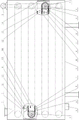
图1是本发明实施例的结构原理图。 Fig. 1 is a structural schematic diagram of an embodiment of the present invention.
图2是图1所示实施例的第Ⅰ局部放大剖视图。 Fig. 2 is a first partial enlarged sectional view of the embodiment shown in Fig. 1 .
图3是图1所示实施例的第Ⅱ局部放大剖视图。 Fig. 3 is a second partial enlarged sectional view of the embodiment shown in Fig. 1 .
图4是图1所示实施例的A向局部视图。 Fig. 4 is a partial view along the direction A of the embodiment shown in Fig. 1 .
图5是图1所示实施例的拨料杆结构简图。 Fig. 5 is a schematic diagram of the structure of the shift rod in the embodiment shown in Fig. 1 .
具体实施方式 Detailed ways
1、箱体 2、传动装置 3、进料口 4、出料口 5、轴 6、链轮 7、链条8、拨料杆 9、螺钉 10、托料板 11、导料槽 12、辐射架 13、红外辐射元件14、保温层。
1.
在图1~5所示的实施例中:长方形箱体1顶部左端设有进料口3,同一端在箱体1底部设有出料口4。箱体1内沿长度方向设有4条输送装置,同一输送装置的两条轴5水平布置在箱体1沿长度方向的两端,两条轴5两端均支承在箱体1的立壁上,且轴5的轴线垂直于箱体1的长度方向;安装在箱体1顶部远离进料口3的右端的传动装置2,通过各输送装置位于传动装置2下方的轴5穿过箱体1立壁后的伸出端逐级驱动输送装置运转;每条轴5两端靠近箱体1内壁处各安装有两个链轮6,每条输送装置的两条轴5靠近箱体1同一侧内壁处的两个链轮6上分别挂有一条链条7。Ⅰ型和Ⅱ型两种长方形环状拨料杆8除长度不同、即拨料杆8与长度方向相垂直的两条短边外表面之间的距离不同之外,拨料杆8的结构形状、宽度、厚度及环的壁厚完全相同;Ⅰ型拨料杆8的长度等于同一输送装置的两条链条7之间最近的内链节外表面之间的距离,Ⅱ型拨料杆8的长度等于同一输送装置的两条链条7之间最近的外链节外表面之间的距离。Ⅰ型拨料杆8的两条短边外表面中部通过4个螺钉9固定在同一输送装置的两条链条7内侧的内链节外表面沿着长度方向的中线处,且Ⅰ型拨料杆8的短边与链条7的内链节垂直;Ⅱ型拨料杆8的两条短边外表面中部通过4个螺钉9固定在同一输送装置的两条链条7内侧的外链节外表面沿着长度方向的中线处,且Ⅱ型拨料杆8的短边与链条7的外链节垂直;相邻两拨料杆8内侧表面之间的距离、即“链条7的节距-拨料杆8的厚度”大于玉米穗的直径。每条输送装置的4个链轮6之间对应于链条7的上、下两段水平段分别设置有托料板10,且上、下两片托料板10的上平面分别位于与4个链轮6的分度圆同时相切的上、下两个平面内;托料板10宽度小于同一输送装置两条链条7的销轴内端面之间的距离。在箱体1左端进料口3下方的各链轮6处,沿着链条7水平段的移动方向,位于链轮6上方的托料板10起始于链轮6的分度圆右象限点与链轮6轴线之间的上方;位于链轮6下方的托料板10终止于链轮6的分度圆右象限点的右侧下方;对应于托料板10末端的下方、两个链轮6之间设置有导料槽11,位于箱体1最下面链轮6处的导料槽11即为出料口4;位于最上层输送装置上方的托料板10起始端的上方、即箱体1顶部的即为进料口2。在箱体1右端传动装置2下方的各链轮6处,沿着链条7水平段的移动方向,位于链轮6上方的托料板10终止于链轮6的分度圆左象限点的左侧上方,对应于托料板10末端的下方、两个链轮6之间设置有导料槽11;位于链轮6下方的托料板10起始于链轮6的分度圆左象限点下方。位于各托料板10上方的辐射装置高度可调的辐射架12吊装于箱体1上,单方向朝着托料板10向下辐射红外线的各红外辐射元件13两端安装在辐射架12上。
In the embodiment shown in FIGS. 1-5 : the top left end of the
Claims (2)
Priority Applications (1)
| Application Number | Priority Date | Filing Date | Title |
|---|---|---|---|
| CN2013100568477A CN103081991B (en) | 2013-02-23 | 2013-02-23 | Continuous type infrared corncob drying machine |
Applications Claiming Priority (1)
| Application Number | Priority Date | Filing Date | Title |
|---|---|---|---|
| CN2013100568477A CN103081991B (en) | 2013-02-23 | 2013-02-23 | Continuous type infrared corncob drying machine |
Publications (2)
| Publication Number | Publication Date |
|---|---|
| CN103081991A CN103081991A (en) | 2013-05-08 |
| CN103081991B true CN103081991B (en) | 2013-10-16 |
Family
ID=48195529
Family Applications (1)
| Application Number | Title | Priority Date | Filing Date |
|---|---|---|---|
| CN2013100568477A Expired - Fee Related CN103081991B (en) | 2013-02-23 | 2013-02-23 | Continuous type infrared corncob drying machine |
Country Status (1)
| Country | Link |
|---|---|
| CN (1) | CN103081991B (en) |
Families Citing this family (7)
| Publication number | Priority date | Publication date | Assignee | Title |
|---|---|---|---|---|
| CN103766482A (en) * | 2014-02-24 | 2014-05-07 | 山东理工大学 | Infrared corncob drying machine with stirring wheels |
| CN103843884B (en) * | 2014-03-24 | 2015-03-18 | 山东理工大学 | Infrared corn cob drying machine with shifting mechanisms |
| CN103913052B (en) * | 2014-04-21 | 2015-08-12 | 山东理工大学 | The two-sided conveyer dryer of scraper-type |
| CN103947749B (en) * | 2014-05-19 | 2015-09-09 | 山东理工大学 | Fractional Drying Process of Infrared Corn Ears |
| CN103960355B (en) * | 2014-05-28 | 2016-02-10 | 山东理工大学 | The infrared corncob drier of straight-bar type |
| CN104855507B (en) * | 2015-04-27 | 2017-12-15 | 山东理工大学 | Elastic blanking infrared corncob drying machine |
| CN112189783A (en) * | 2020-09-30 | 2021-01-08 | 柳州市汇方科技有限公司 | A rice noodle aging device |
Citations (5)
| Publication number | Priority date | Publication date | Assignee | Title |
|---|---|---|---|---|
| CN2691270Y (en) * | 2004-04-29 | 2005-04-13 | 山东理工大学 | Far infra-red apparatus for vegetable dewatering |
| CN2860116Y (en) * | 2006-02-15 | 2007-01-24 | 山东理工大学 | Far infrared vegetable dehydrator with anti-shedding device |
| CN2875087Y (en) * | 2006-02-15 | 2007-03-07 | 山东理工大学 | Far infrared equipment for dehydration of vegetables having driving plate structure |
| CN2877321Y (en) * | 2006-02-15 | 2007-03-14 | 山东理工大学 | Current Combination and wind guiding type far Infrared vegetable dehydrating device |
| CN101744352A (en) * | 2010-01-18 | 2010-06-23 | 山东理工大学 | Vegetable dehydrator with elastic dialing mechanism |
-
2013
- 2013-02-23 CN CN2013100568477A patent/CN103081991B/en not_active Expired - Fee Related
Patent Citations (5)
| Publication number | Priority date | Publication date | Assignee | Title |
|---|---|---|---|---|
| CN2691270Y (en) * | 2004-04-29 | 2005-04-13 | 山东理工大学 | Far infra-red apparatus for vegetable dewatering |
| CN2860116Y (en) * | 2006-02-15 | 2007-01-24 | 山东理工大学 | Far infrared vegetable dehydrator with anti-shedding device |
| CN2875087Y (en) * | 2006-02-15 | 2007-03-07 | 山东理工大学 | Far infrared equipment for dehydration of vegetables having driving plate structure |
| CN2877321Y (en) * | 2006-02-15 | 2007-03-14 | 山东理工大学 | Current Combination and wind guiding type far Infrared vegetable dehydrating device |
| CN101744352A (en) * | 2010-01-18 | 2010-06-23 | 山东理工大学 | Vegetable dehydrator with elastic dialing mechanism |
Also Published As
| Publication number | Publication date |
|---|---|
| CN103081991A (en) | 2013-05-08 |
Similar Documents
| Publication | Publication Date | Title |
|---|---|---|
| CN103081991A (en) | Continuous type infrared corncob drying machine | |
| CN201463482U (en) | Mesh-belt type drying equipment | |
| CN101744352A (en) | Vegetable dehydrator with elastic dialing mechanism | |
| CN104686649B (en) | Overturn blanking infrared corncob drying machine | |
| CN102599625B (en) | Method and device for direct drying and redrying of tobacco strips | |
| CN103070458B (en) | Rotating rod type infrared corncob drier | |
| CN102721271A (en) | Ginger rapid drying device | |
| CN1808030A (en) | Apparatus for processing grain using microwave energy | |
| CN104472679A (en) | Spiral slideway infrared corncob drying machine | |
| CN104188070B (en) | The vegetables microwave dryer that material surface temperature accurately controls and method | |
| CN113632833B (en) | Grain circulating dryer based on graphene far-infrared heating and drying method thereof | |
| CN204969193U (en) | Continuous type microwave drying brown rice equipment that sprouts | |
| CN103070233B (en) | Continuous corncob dryer | |
| CN103960355B (en) | The infrared corncob drier of straight-bar type | |
| CN103081993A (en) | Infrared corncob drying machine of limiting sleeve | |
| CN108020064A (en) | A kind of drying unit | |
| CN103766482A (en) | Infrared corncob drying machine with stirring wheels | |
| CN103913052B (en) | The two-sided conveyer dryer of scraper-type | |
| CN103947749B (en) | Fractional Drying Process of Infrared Corn Ears | |
| CN103070236B (en) | Cooling discharge type corncob drying machine | |
| CN104855507B (en) | Elastic blanking infrared corncob drying machine | |
| CN205351998U (en) | Brush silk raw materials section drying device | |
| CN208936728U (en) | A kind of movable grain drying machine | |
| CN207897862U (en) | One cultivates peanut drying equipment | |
| CN103843884A (en) | Infrared corn cob drying machine with shifting mechanisms |
Legal Events
| Date | Code | Title | Description |
|---|---|---|---|
| C06 | Publication | ||
| PB01 | Publication | ||
| C10 | Entry into substantive examination | ||
| SE01 | Entry into force of request for substantive examination | ||
| C14 | Grant of patent or utility model | ||
| GR01 | Patent grant | ||
| C17 | Cessation of patent right | ||
| CF01 | Termination of patent right due to non-payment of annual fee |
Granted publication date: 20131016 Termination date: 20140223 |