CN103066780A - Stator roll-over protection tool of large permanent magnetic direct-driven wind turbine generator - Google Patents

Stator roll-over protection tool of large permanent magnetic direct-driven wind turbine generator Download PDF

Info

Publication number
CN103066780A
CN103066780A CN2013100286080A CN201310028608A CN103066780A CN 103066780 A CN103066780 A CN 103066780A CN 2013100286080 A CN2013100286080 A CN 2013100286080A CN 201310028608 A CN201310028608 A CN 201310028608A CN 103066780 A CN103066780 A CN 103066780A
Authority
CN
China
Prior art keywords
stator
bearing cylinder
tool set
load
protecting tool
Prior art date
Legal status (The legal status is an assumption and is not a legal conclusion. Google has not performed a legal analysis and makes no representation as to the accuracy of the status listed.)
Granted
Application number
CN2013100286080A
Other languages
Chinese (zh)
Other versions
CN103066780B (en
Inventor
李相兵
王杰
余乐
雷林璋
郭云强
汤兰海
Current Assignee (The listed assignees may be inaccurate. Google has not performed a legal analysis and makes no representation or warranty as to the accuracy of the list.)
Hami Zhongche New Energy Motor Co Ltd
Jiangsu Zhongche Motor Co Ltd
Original Assignee
Jiangsu CSR Electric Co Ltd
Priority date (The priority date is an assumption and is not a legal conclusion. Google has not performed a legal analysis and makes no representation as to the accuracy of the date listed.)
Filing date
Publication date
Application filed by Jiangsu CSR Electric Co Ltd filed Critical Jiangsu CSR Electric Co Ltd
Priority to CN201310028608.0A priority Critical patent/CN103066780B/en
Publication of CN103066780A publication Critical patent/CN103066780A/en
Application granted granted Critical
Publication of CN103066780B publication Critical patent/CN103066780B/en
Active legal-status Critical Current
Anticipated expiration legal-status Critical

Links

Images

Landscapes

  • Iron Core Of Rotating Electric Machines (AREA)
  • Manufacture Of Motors, Generators (AREA)

Abstract

The invention provides a stator roll-over protection tool of a large permanent magnetic direct-driven wind turbine generator. The stator roll-over protection tool comprises a bearing cylinder, a stop ring, a support rib, and a mounting bottom plate, wherein the stop ring is arranged on both ends of the bearing cylinder; the bearing cylinder is arranged on the upper end of the support rib; and the mounting bottom plate is arranged on the lower end of the support rib. The tool provided by the invention has the advantages of simple structure, low cost and convenience in use, and can effectively prevent the coil from being crushed by a sling during rolling of the stator, thereby ensuring the stator quality and reducing loss of stator manufacturers.

Description

A kind of large directly driven permanent magnet wind generating stator stands up protecting tool set-up
[technical field]
The present invention relates to a kind of stator and stand up protecting tool set-up, relate in particular to a kind of large directly driven permanent magnet wind generating stator and stand up protecting tool set-up.
[background technology]
The large directly driven permanent magnet wind generating stator needs dipping lacquer in production technology, stator is to be in vertical state (and head end up) when entering the dipping lacquer operation, needs to use overhead traveling crane that stator is become horizontal state by vertical state turnover; When stator enters finished product ending operation, need up and down all embeddings of both sides, thus to use overhead traveling crane with stator by and head end is turned into up and head end down.In the stator switching process, as without any safeguard measure, suspender can contact with stator coil, and weighs coil wounded, causes coil to be scrapped; If coil is weighed wounded and then causes whole stator to be scrapped behind dipping lacquer.
[summary of the invention]
The object of the present invention is to provide a kind of large directly driven permanent magnet wind generating stator to stand up protecting tool set-up.
For reaching aforementioned purpose; a kind of large directly driven permanent magnet wind generating stator stands up protecting tool set-up; it is characterized in that: described frock comprises load-bearing cylinder, back-up ring, brace rod and mounting base; described back-up ring is arranged at load-bearing cylinder two ends; described brace rod upper end is provided with the load-bearing cylinder, and described brace rod lower end is provided with mounting base.
According to one embodiment of present invention, described load-bearing cylinder width is more than or equal to the hoist cable width, and the load-bearing cylinder blocks hoist cable fully.
According to one embodiment of present invention, described back-up ring edge any point apart from the distance of load-bearing cylinder center line greater than load-bearing cylinder radius.
According to one embodiment of present invention, described back-up ring is cylindrical.
According to one embodiment of present invention, described frock width is greater than coil width, and described frock is blocked coil fully, and contactless with coil, and coil does not contact hoist cable.
According to one embodiment of present invention, the structure of described brace rod is that left end down is bent into " 7 " font.
According to one embodiment of present invention, be provided with installing hole on the described mounting base, be used for protecting tool set-up and stator are fixed.
Beneficial effect of the present invention: compared with prior art; stator of the present invention stands up protecting tool set-up and comprises: load-bearing cylinder, back-up ring, brace rod and mounting base; described back-up ring is arranged at load-bearing cylinder two ends; described brace rod upper end is provided with the load-bearing cylinder, and described brace rod lower end is provided with mounting base.This device has simple in structure, and is easy to use, with low cost, safe and reliable, efficiently solves the risk that suspender belt in the process of standing up weighs coil wounded, can guarantee the quality of stator.
[description of drawings]
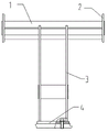
Fig. 1 is the front view that a kind of large directly driven permanent magnet wind generating stator of the present invention stands up protecting tool set-up.
Fig. 2 is the vertical view that a kind of large directly driven permanent magnet wind generating stator of the present invention stands up protecting tool set-up.
Fig. 3 is the left view that a kind of large directly driven permanent magnet wind generating stator of the present invention stands up protecting tool set-up.
Fig. 4 is the schematic diagram after a kind of large directly driven permanent magnet wind generating stator of the present invention stands up the installation of protecting tool set-up.
[embodiment]
Alleged " embodiment " or " embodiment " refer to be contained in special characteristic, structure or the characteristic at least one implementation of the present invention herein.Different local in this manual " in one embodiment " that occur not are all to refer to same embodiment, neither be independent or the embodiment mutually exclusive with other embodiment optionally.
See also Fig. 1 to shown in Figure 3, it shows that a kind of large directly driven permanent magnet wind generating stator of one embodiment of the present of invention stands up front view, vertical view and the left view of protecting tool set-up.Such as Fig. 1 or shown in Figure 3, protecting tool set-up of the present invention comprises load-bearing cylinder 1, back-up ring 2, brace rod 3, mounting base 4, and protecting tool set-up of the present invention also comprises installing hole 8 as shown in Figure 2.
In one embodiment of the invention; a kind of large directly driven permanent magnet wind generating stator stands up protecting tool set-up and comprises: load-bearing cylinder 1, back-up ring 2, brace rod 3 and mounting base 4; described back-up ring 2 is arranged at load-bearing cylinder 1 two ends; described brace rod 3 upper ends are provided with load-bearing cylinder 1, and described brace rod 3 lower ends are provided with mounting base 4.
As shown in Figure 4, load-bearing cylinder 1 width is more than or equal to the hoist cable width, and load-bearing cylinder 1 blocks hoist cable fully.Back-up ring 2 edge any points are apart from the distance of the load-bearing cylinder 1 center line radius greater than load-bearing cylinder 1.The shape of back-up ring 2 can arrange arbitrarily, is preferably cylindrical.
Described protecting tool set-up 7 width that stand up are greater than the width of coil 6 as shown in Figure 4, and described frock 7 is blocked coil 6 fully, and contactless with coil 6, and coil 6 does not contact hoist cable.Arranging like this can prevent that coil is damaged in the handling process.The shape of brace rod 3 can arrange arbitrarily, and the structure of brace rod 3 can be set to left end and down be bent into " 7 " font.
As shown in Figure 2, be provided with installing hole 8 on the mounting base 4, be used for protecting tool set-up and stator are fixed.
In various embodiments of the present invention, the quantity of described installing hole 8 can arrange arbitrarily, and fixed form also can be multiple, is preferably bolt and fixes.The shape of back-up ring 2 and brace rod 3 and size are blocked coil 6 apart from the distance of load-bearing cylinder 1 center line greater than the radius of load-bearing cylinder 1, the described protecting tool set-up 7 that stands up fully reaching back-up ring 2 edge any points; and contactless with coil 6; coil 6 does not contact under the condition of hoist cable, can arrange arbitrarily.This protecting tool set-up can be other profiles, as long as can reach same effect, all belongs to this scope.
This stator stands up protecting tool set-up, has characteristics simple in structure, easy to use, with low cost, can effectively solve the risk that suspender belt in the process of standing up weighs coil wounded, can guarantee the quality of stator, reduces stator production supplier's loss.
Above-mentioned explanation has fully disclosed the specific embodiment of the present invention.It is to be noted, above embodiment is only in order to illustrate technical scheme of the present invention, and it is unrestricted, although with reference to preferred embodiment the present invention is had been described in detail, those of ordinary skill in the art is to be understood that, can make amendment or be equal to replacement technical scheme of the present invention, and not break away from the spirit and scope of technical solution of the present invention, it all should be encompassed in the middle of the claim scope of the present invention.

Claims (7)

1. a large directly driven permanent magnet wind generating stator stands up protecting tool set-up; it is characterized in that: described frock (7) comprises load-bearing cylinder (1), back-up ring (2), brace rod (3) and mounting base (4); described back-up ring (2) is arranged at load-bearing cylinder (1) two ends; described brace rod (3) upper end is provided with load-bearing cylinder (1), and described brace rod (3) lower end is provided with mounting base (4).
2. protecting tool set-up as claimed in claim 1, it is characterized in that: described load-bearing cylinder (1) width is more than or equal to the hoist cable width.
3. protecting tool set-up as claimed in claim 1 is characterized in that: described back-up ring (2) edge any point apart from the distance of load-bearing cylinder (1) center line greater than load-bearing cylinder (1) radius.
4. protecting tool set-up as claimed in claim 3 is characterized in that: described back-up ring (2) is for cylindrical.
5. protecting tool set-up as claimed in claim 1, it is characterized in that: described frock (7) width is greater than coil (6) width.
6. protecting tool set-up as claimed in claim 5, it is characterized in that: the structure of described brace rod (3) is that left end down is bent into " 7 " font.
7. protecting tool set-up as claimed in claim 1, it is characterized in that: be provided with installing hole (8) on the described mounting base (4), described installing hole (8) can be fixed protecting tool set-up and stator.
CN201310028608.0A 2013-01-25 2013-01-25 A kind of large directly driven permanent magnet wind generating stator stands up protecting tool set-up Active CN103066780B (en)

Priority Applications (1)

Application Number Priority Date Filing Date Title
CN201310028608.0A CN103066780B (en) 2013-01-25 2013-01-25 A kind of large directly driven permanent magnet wind generating stator stands up protecting tool set-up

Applications Claiming Priority (1)

Application Number Priority Date Filing Date Title
CN201310028608.0A CN103066780B (en) 2013-01-25 2013-01-25 A kind of large directly driven permanent magnet wind generating stator stands up protecting tool set-up

Publications (2)

Publication Number Publication Date
CN103066780A true CN103066780A (en) 2013-04-24
CN103066780B CN103066780B (en) 2015-09-23

Family

ID=48109276

Family Applications (1)

Application Number Title Priority Date Filing Date
CN201310028608.0A Active CN103066780B (en) 2013-01-25 2013-01-25 A kind of large directly driven permanent magnet wind generating stator stands up protecting tool set-up

Country Status (1)

Country Link
CN (1) CN103066780B (en)

Citations (5)

* Cited by examiner, † Cited by third party
Publication number Priority date Publication date Assignee Title
CN201504155U (en) * 2009-09-24 2010-06-09 泰豪科技股份有限公司 Stator turn over tool
CN201742247U (en) * 2010-07-09 2011-02-09 泰豪科技股份有限公司 Generator unit stator assembling and hoisting flip tool
CN201830104U (en) * 2010-10-19 2011-05-11 天津市天发重型水电设备制造有限公司 Lifting frame for hanging magnetic pole of large hydrogenerator rotor
CN202160075U (en) * 2011-06-20 2012-03-07 朱明初 Rotor assembling suspension hook
CN203166713U (en) * 2013-01-25 2013-08-28 江苏南车电机有限公司 Stator turning-over protective tool for large-scale permanent-magnetic direct-driven wind power generator

Patent Citations (5)

* Cited by examiner, † Cited by third party
Publication number Priority date Publication date Assignee Title
CN201504155U (en) * 2009-09-24 2010-06-09 泰豪科技股份有限公司 Stator turn over tool
CN201742247U (en) * 2010-07-09 2011-02-09 泰豪科技股份有限公司 Generator unit stator assembling and hoisting flip tool
CN201830104U (en) * 2010-10-19 2011-05-11 天津市天发重型水电设备制造有限公司 Lifting frame for hanging magnetic pole of large hydrogenerator rotor
CN202160075U (en) * 2011-06-20 2012-03-07 朱明初 Rotor assembling suspension hook
CN203166713U (en) * 2013-01-25 2013-08-28 江苏南车电机有限公司 Stator turning-over protective tool for large-scale permanent-magnetic direct-driven wind power generator

Also Published As

Publication number Publication date
CN103066780B (en) 2015-09-23

Similar Documents

Publication Publication Date Title
CN203237913U (en) Lifting appliance for L-shaped flange tower barrel
CN203781754U (en) Movable weight hoister
CN203166713U (en) Stator turning-over protective tool for large-scale permanent-magnetic direct-driven wind power generator
CN103066780B (en) A kind of large directly driven permanent magnet wind generating stator stands up protecting tool set-up
CN203922365U (en) A kind of maintenance joint frame of building hoist
CN104003224A (en) Steel strip coiler
CN203699679U (en) Lifting appliance for lifting wire coil
CN203082534U (en) A kind of anti-dumping SF6 gas cylinder tooling
CN204369417U (en) Used in nuclear power station heavy-caliber gate valve valve plate lifting device
CN203205722U (en) Electrical cabinet convenient to lift
CN203545516U (en) Simple hoisting frame of electric transducer
CN203306970U (en) Jacking tool used for jacking heavy part in narrow space
CN206128781U (en) Stereo garage is with carrying sweep
CN202231315U (en) Electrical complete switch cabinet hoisting support
CN203922177U (en) A kind of Steel Tape Recoiler
CN204847783U (en) Roof beam is hung to hoist
CN204067965U (en) A kind of transportation trolley
CN203536818U (en) Auxiliary ladder for assembly of switch cabinet
CN203166656U (en) Support base for transporting stator of large permanent magnetic direct-driven wind turbine generator
CN205666366U (en) Portable power source socket
CN103066779B (en) Method for rolling over stator crown block of large permanent magnetic direct-driven wind turbine generator
CN203542055U (en) Ladder structure of double-column vertical lathe
CN203545456U (en) Movable elevator
CN203396394U (en) Splitting type detection system for pole tower inclination
CN202691292U (en) Cross structure

Legal Events

Date Code Title Description
C06 Publication
PB01 Publication
C10 Entry into substantive examination
SE01 Entry into force of request for substantive examination
C14 Grant of patent or utility model
GR01 Patent grant
C56 Change in the name or address of the patentee
CP03 Change of name, title or address

Address after: 224100 Yancheng City Economic Development Zone, Jiangsu No. 111 Jin Hai Road

Patentee after: CSR JIANGSU MOTOR CO., LTD.

Address before: 224100 No. 111, Jinhai Road, Dafeng Economic Development Zone, Jiangsu, Yancheng City

Patentee before: Jiangsu CSR Electric Co., Ltd.

CP02 Change in the address of a patent holder

Address after: 224100 Yancheng City Dafeng Economic Development Zone, Jiangsu, No. 111 Jin Hai Road

Patentee after: CSR JIANGSU MOTOR CO., LTD.

Address before: 224100 Yancheng City Economic Development Zone, Jiangsu No. 111 Jin Hai Road

Patentee before: CSR JIANGSU MOTOR CO., LTD.

TR01 Transfer of patent right

Effective date of registration: 20171011

Address after: 224100 No. 111 Jinhai Road, Dafeng Economic Development Zone, Jiangsu, Yancheng

Co-patentee after: Hami Zhongche new energy motor Co. Ltd.

Patentee after: Jiangsu Zhongche Motor Co., Ltd.

Address before: 224100 Yancheng City Dafeng Economic Development Zone, Jiangsu, No. 111 Jin Hai Road

Patentee before: Jiangsu Zhongche Motor Co., Ltd.