Bow-type tractor
Technical field
The present invention relates to a kind of farm machinery, especially a kind of bow-type tractor.
Background technology
Walker tractor is a kind of compact tractor, the multi-purpose travelling machinery that is drawn and transported by being mainly used in of forming of driving engine, chassis, the system such as electric.It is to lean on the power of combustion engine through driving system that walker tractor can travel, the drive wheel that obtains driving torque is little to ground by tire tread and surface of tyre again, horizontal applied force backward, simple in structure, power is less, be applicable to small size and plough, holding up arm-rest frame control steering unit, traction or driving matched farm tool by chaufeur and carrying out operation.
The disk tractor of articulated steering mechanism that has openly used in the market, in the mountain area or intersected country generally adopt the transport plane of walker tractor repacking or driven the transportation mode in compartment by four-wheeled tractor, some R﹠D institutions, company in addition comprise the individual all utility model some articulated tractors, open source literature has also been reported some, as:
But Chinese patent application 200820113729.X disclose a kind of seal drive the building again can articulated steering also front-back full-driving tractor, it mainly is comprised of change speed gear box, universal engage a gear bar, rear drive transmission shaft, driving building, under-carriage, back axle, it is reasonable that this overlaps newly-designed gearbox designs, and high and low gear when front and back drive simultaneously, each gear that reverses gear are synchronous.It is characterized in that: keeping having transformed handling device on its farmland operation performance basis of agro-industrial 12 types, at first be that change speed gear box has increased rear output power shaft, be convenient to articulate farm implements, can drive to back axle again, the full driving is convenient to transport at wide paths for tractors in the countryside before and after making it to become; Next is to transform former putting into gear as the universal bar of putting into gear, and both can seal the driving building, again can articulated steering, and make operation more comfortable, more meet the human oriented design requirement.
2. Chinese patent application numbers 200910013612.3 discloses a kind of 4-wheel driven articulated tractor trucks, comprise frame and back axle assembly, in frame driving engine, power-transfer clutch, hydraulic steering gear and front axle assy are installed, front axle assy comprises the propons case, be connected with main-gear box on the propons case, be connected with transfer gear box on the main-gear box, transfer gear box is provided with the transfer gear box power take-off shaft; Back axle assembly comprises wagon box and rear axle shaft, the back axle Transaxle is installed on the rear axle shaft, be in transmission connection by universal drive shaft between back axle Transaxle and the transfer gear box power take-off shaft, this utility model makes wagon box obtain power-handling capability, solve tire skidding under the poor and load of hill climbing ability, greatly improved the load-carrying ability of transport trolley, reduced energy resource consumption, prevented that tire from wearing and tearing too early, prolonged service life.
3. Chinese patent application numbers 200920088617.8 discloses a kind of Novel control mechanism of disk tractor of articulated steering mechanism, comprise vertical diesel engine assembly, transmission assembly, steering wheel assembly, it is characterized in that: described pull bar with universal-joint vertically is arranged between master lever and the main transformer lever, the one end master lever interior with being arranged on operator's compartment is connected, and its other end is connected with the main transformer lever on transmission assembly top.
But, after investigation, find, more than disclosed patent also have some defectives, their common shortcoming is: inconvenient operation, hill climbing ability is low, car load is long, fuselage is heavier, and turn radius is large, safety performance is relatively poor, and energy consumption is larger, major cause is that propons and change speed gear box are integrated together, and driving engine is on propons, so structure is very complicated, and range of use and intensity are just smaller comparatively speaking, poor-performing, and, brake and shock-absorbing can not be installed on propons, handling very complicated and unreliable, cost is very high, especially mountain region or high-land, ground relief, the trac. front-wheel will produce because beating and rock, lack of equilibrium, even can cause turning excessively to cause roll-over accident.So these above defectives become the technical bottleneck of Tractor Industry.
In order to solve the problems of the technologies described above, Chinese patent application numbers 201110054809.9 discloses a kind of articulated tractor, comprise driving engine, transmission gearbox, axis of traction, change speed gear box, auxiliary gear box, the chassis, control the position, railway carriage, transmission shaft and tear the waist point open, pass through belt-driving between driving engine and the transmission gearbox, auxiliary gear box is connected with change speed gear box, be characterized in: before the bowing of trac. a little is located at and controls the position, after change speed gear box is installed in and bows a little, axis of traction is solid construction or hollow structure, the chassis is equipped with and can bows, the towing bracket device of steering balance, have propons and/or the back axle of damping and brake and can grow the universal transmission mechanism that transmits apart from power, described propons separates with change speed gear box, have simple in structurely, with low cost, operation is reliable, safety durable, wide adaptability turns to flexibly, and operating efficiency is high, the advantages such as purposes is wide, and load-carrying is many.But still there is following defective in this utility model:
1. the bearing of this device front axle support links to each other with drive wheel, and whole support and drive wheel rotate simultaneously when turning to, and turn to effort, it is very heavy to beat direction, and the little and tire of steering angle weares and teares easily, and is particularly inadequate at mechanical precision, under the operating mode of soil uneven, this shortcoming is particularly serious;
2. universal transmission mechanism adopts long shaft transmission, and long shaft transmission shaft universal-joint or multi-directional ball very easily cause the transmission shaft damage or fracture not at the center of bowing during turning;
3. universal transmission mechanism comprises transmission gear, transition gear and gear, causes mechanism's volume larger, is difficult for installing and maintenance; Gear is more, and it is larger to rub, and especially when speed-raising or deceleration, power changes the most obvious.
Summary of the invention
The objective of the invention is the deficiency that proposes in the above-mentioned technology, provide a kind of cost low, turn to lithe, good stability, steering angle is large, tire is not easy to wear, the axis of traction bearing capacity is strong, the bow-type tractor of easily installing and keeping in repair.
For achieving the above object, the present invention is achieved by the following technical solutions:
A kind of bow-type tractor, comprise driving engine, transmission gearbox, output shaft, axis of traction, change speed gear box, auxiliary gear box, chassis, control position, railway carriage, transmission shaft and bow a little, pass through belt-driving between driving engine and the transmission gearbox, auxiliary gear box is connected with change speed gear box, bow a little be located at control the position before, after change speed gear box was installed in and bows a little, the chassis was equipped with and can bows, the draw gear of steering balance and the universal transmission mechanism that can power transmits; Described draw gear comprises propons, front bridge grider support, transmission shaft, axis of traction, back axle and back axle main girder, and propons is connected with the chassis, and the propons two ends are provided with steering swivel, and steering swivel is connected with drive wheel by steering stub axle.
Above-mentioned universal transmission mechanism comprises power-transfer clutch, gear, universal-joint, change speed gear box and auxiliary gear box, the power of driving engine passes to power-transfer clutch by belt, power-transfer clutch passes to the universal-joint break-in through gear, be passed to auxiliary gear box by change speed gear box again after outputing to change speed gear box by output shaft, at last, auxiliary gear box is controlled single forerunner or rear-guard with power distribution or is driven before and after the while.
Above-mentioned back axle main girder the same side is equipped with steering wheel and adapter shaft, one end and the steering wheel of adapter shaft are flexibly connected by connecting lever, the other end is flexibly connected with the spindle arm that is fixed on one jiao on front bridge grider support by drag link B, steering swivel is provided with the steering swivel connecting lever, and described steering swivel connecting lever is flexibly connected by drag link A and adapter shaft.
Above-mentioned back axle main girder is provided with steering wheel, steering wheel and drag link B one end are flexibly connected by connecting lever, the drag link B other end is flexibly connected with the spindle arm that is fixed on one jiao on front bridge grider support, steering swivel is provided with the steering swivel connecting lever, and described steering swivel connecting lever is flexibly connected by drag link A and back axle main girder.
Above-mentioned flexible connection is that bulb type or bearing-type connect.
Above-mentioned axis of traction is hollow structure, and transmission shaft passes from the axis of traction inside center, and axis of traction two is provided with the bearing for the fixed conveyor axle; Described transmission shaft is connected with propons by universal-joint or multi-directional ball.
Shock absorption device and brake gear are installed on above-mentioned propons and/or the back axle; Shock absorption device comprises front axle damper device and rear axle shock-absorbing device, and described shock absorption device is spring plate.
The invention has the beneficial effects as follows:
1. the propons two ends are provided with steering swivel, and steering swivel has certain steering angle, under the combined action of drag link A and drag link B, can make the bow-type tractor direction grasp lithe, good stability, easy operating, and steering angle is large, tire is not easy to wear.
2. transmission device has reduced transmission gear and transition gear, not only makes mechanism's smaller volume, and has reduced friction force, has saved cost and the energy.
3. transmission shaft of the present invention passes from the axis of traction center, so that Universal drive has reduced the damage of transmission shaft or the probability that fractures so greatly in joint waist dot center; And axis of traction is hollow structure, and two is provided with the bearing for the fixed conveyor axle, has strengthened the bearing capacity of axis of traction, and trac. is avoided and collision on the ground when rough road traveling effectively, can safer travelling.
4. the invention solves propons and back axle and all shock absorption device and braking mechanism can be installed, the large gordian technique difficult problem that can carry out is simultaneously driven in front and back, has greatly strengthened traveling comfort and the safety of driving.
Description of drawings
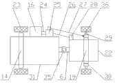
Fig. 1 is bow-type tractor basic structure simplified schematic diagram of the present invention.
Fig. 2 is the structural representation of draw gear embodiment 1 of the present invention.
Fig. 3 is the structural representation of universal transmission mechanism of the present invention.
Fig. 4 is the structural representation of draw gear embodiment 2 of the present invention.
Fig. 5 is transmission shaft of the present invention and axis of traction unitized construction scheme drawing.
Description of reference numerals:
Driving engine 1, belt pulley 2, belt 3, transmission gearbox 4, output shaft 5, axis of traction 6, change speed gear box 7, auxiliary gear box 8, position 10 is controlled, railway carriage 11, rear axle shock-absorbing device 12 in chassis 9, rear-wheel brake equipment 13, back axle 14, transmission shaft 15, steering wheel 16, bow a little 17, draw gear 18, propons 19, front axle damper device 20, front wheel brake device 21, front bridge grider support 22, drive wheel 23, connecting lever 24, adapter shaft 25, drag link B 26, drag link A 27, spindle arm 28, steering stub axle 29, steering swivel 30, back axle main girder 31, power-transfer clutch 32, gear 33, universal-joint 34, bearing 35, steering swivel connecting lever 36.
The specific embodiment
Below in conjunction with drawings and Examples bow-type tractor of the present invention is further described, but embodiments of the present invention are not limited to the scope that embodiment represents.
Embodiment 1
Shown in Fig. 1 ~ 2, a kind of bow-type tractor, comprise driving engine 1, transmission gearbox 4, output shaft 5, axis of traction 6, change speed gear box 7, auxiliary gear box 8, chassis 9, control position 10, railway carriage 11, transmission shaft 15 and bow a little 17, pass through belt 3 transmissions between driving engine 1 and the transmission gearbox 4, auxiliary gear box 8 is connected with change speed gear box 7, bow a little 17 be located at control position 10 before, change speed gear box 7 is installed in bows a little after 17, and chassis 9 is equipped with and can bows, the draw gear 18 of steering balance and the universal transmission mechanism that can power transmits; Described draw gear 18 comprises propons 19, front bridge grider support 22, transmission shaft 15, axis of traction 6, back axle 14 and back axle main girder 31, propons 19 is connected with chassis 9, propons 19 two ends are provided with steering swivel 30, and steering swivel 30 is connected with drive wheel 23 by steering stub axle 29; Back axle main girder 31 the same sides are equipped with steering wheel 16 and adapter shaft 25, one end of adapter shaft 25 and steering wheel 16 are flexibly connected by connecting lever 24, the other end is flexibly connected with the spindle arm 28 that is fixed on 22 1 jiaos on front bridge grider support by drag link B 26, steering swivel 30 is provided with steering swivel connecting lever 36, and described steering swivel connecting lever 36 is flexibly connected with adapter shaft 25 by drag link A 27.
As shown in Figure 3, described transmission device comprises power-transfer clutch 32, gear 33, universal-joint 34, change speed gear box 7 and auxiliary gear box 8, the power of driving engine 1 passes to power-transfer clutch 32 by belt 3, power-transfer clutch 32 passes to universal-joint 34 break-ins through gear 33, be passed to auxiliary gear box 8 by change speed gear box 7 again after outputing to change speed gear box 7 by output shaft 5, at last, auxiliary gear box 8 is controlled single forerunner or rear-guard with power distribution or is driven before and after the while.
It turns to principle of work:
When A. working, steering wheel 16 starts, promote the drag link B 26 of adapter shaft 25 1 ends by connecting lever 24, drag link B 26 takes advantage of a situation and promotes spindle arm 28 and travel forward, front bridge grider support 22 right-hand turnings to, simultaneously drag link A 27 pulling steering swivel connecting levers 36 backward motions, drive wheel 23 is right-hand turning under the effect that steering swivel 30 moves backward, has realized the purpose that front bridge grider support 22 and drive wheel 23 turn to simultaneously.
When B. working, steering wheel 16 starts, drag link B 26 by connecting lever 24 pulling adapter shafts 25 1 ends, drag link B 26 take advantage of a situation the pulling spindle arm 28 move backward, front bridge grider support 22 left-handed turnings to, drag link A 27 promotion steering swivel connecting levers 36 travel forward simultaneously, and drive wheel 23 is left-handed turning under steering swivel 30 proal effects, has realized the purpose that front bridge grider support 22 and drive wheel 23 turn to simultaneously.
Embodiment 2:
As shown in figs. 1 and 4, it is the scheme drawing of the uneasy load spindle of draw gear of the present invention, a kind of bow-type tractor, comprise driving engine 1, transmission gearbox 4, output shaft 5, axis of traction 6, change speed gear box 7, auxiliary gear box 8, chassis 9, control position 10, railway carriage 11, transmission shaft 15 and bow a little 17, pass through belt 3 transmissions between driving engine 1 and the transmission gearbox 4, auxiliary gear box 8 is connected with change speed gear box 7, bow a little 17 be located at control position 10 before, change speed gear box 7 is installed in bows a little after 17, and chassis 9 is equipped with and can bows, the draw gear 18 of steering balance and the transmission device that can power transmits; Described draw gear 18 comprises propons 19, front bridge grider support 22, transmission shaft 15, axis of traction 6, back axle 14 and back axle main girder 31, propons 19 is connected with chassis 9, propons 19 two ends are provided with the steering swivel 30 of goat's horn shape, and steering swivel 30 is connected with drive wheel 23 by steering stub axle 29; Back axle main girder 31 is provided with steering wheel 16, steering wheel 16 is flexibly connected by connecting lever 24 with drag link B 26 1 ends, drag link B 26 other ends are flexibly connected with the spindle arm 28 that is fixed on 22 1 jiaos on front bridge grider support, steering swivel 30 is provided with steering swivel connecting lever 36, and described steering swivel connecting lever 36 is flexibly connected with back axle main girder 31 by drag link A 27.。
As shown in Figure 3, described transmission device comprises power-transfer clutch 32, gear 33, universal-joint 34, change speed gear box 7 and auxiliary gear box 8, the power of driving engine 1 passes to power-transfer clutch 32 by belt 3, power-transfer clutch 32 passes to universal-joint 34 break-ins through gear 33, be passed to auxiliary gear box 8 by change speed gear box 7 again after outputing to change speed gear box 7 by output shaft 5, at last, auxiliary gear box 8 is controlled single forerunner or rear-guard with power distribution or is driven before and after the while.
It turns to principle of work:
When A. working, steering wheel 16 starts, promote drag link B 26 by connecting lever 24, drag link B 26 takes advantage of a situation and promotes spindle arm 28 and travel forward, front bridge grider support 22 right-hand turnings to, simultaneously drag link A 27 pulling steering swivel connecting levers 36 backward motions, drive wheel 23 is right-hand turning under the effect that steering swivel 30 moves backward, has realized the purpose that front bridge grider support 22 and drive wheel 23 turn to simultaneously.
When B. working, steering wheel 16 starts, by connecting lever 24 pulling drag link B 26, drag link B 26 take advantage of a situation the pulling spindle arm 28 move backward, front bridge grider support 22 left-handed turnings to, drag link A 27 promotion steering swivel connecting levers 36 travel forward simultaneously, and drive wheel 23 is left-handed turning under steering swivel 30 proal effects, has realized the purpose that front bridge grider support 22 and drive wheel 23 turn to simultaneously.