CN102970860A - Non-powered irrigation and fertilization device and non-powered potted cultivation system using the device - Google Patents
Non-powered irrigation and fertilization device and non-powered potted cultivation system using the device Download PDFInfo
- Publication number
- CN102970860A CN102970860A CN2010800673459A CN201080067345A CN102970860A CN 102970860 A CN102970860 A CN 102970860A CN 2010800673459 A CN2010800673459 A CN 2010800673459A CN 201080067345 A CN201080067345 A CN 201080067345A CN 102970860 A CN102970860 A CN 102970860A
- Authority
- CN
- China
- Prior art keywords
- water
- potted plant
- bucket
- water level
- powered
- Prior art date
- Legal status (The legal status is an assumption and is not a legal conclusion. Google has not performed a legal analysis and makes no representation as to the accuracy of the status listed.)
- Pending
Links
Images




Classifications
-
- A—HUMAN NECESSITIES
- A01—AGRICULTURE; FORESTRY; ANIMAL HUSBANDRY; HUNTING; TRAPPING; FISHING
- A01G—HORTICULTURE; CULTIVATION OF VEGETABLES, FLOWERS, RICE, FRUIT, VINES, HOPS OR SEAWEED; FORESTRY; WATERING
- A01G27/00—Self-acting watering devices, e.g. for flower-pots
- A01G27/006—Reservoirs, separate from plant-pots, dispensing directly into rooting medium
-
- A—HUMAN NECESSITIES
- A01—AGRICULTURE; FORESTRY; ANIMAL HUSBANDRY; HUNTING; TRAPPING; FISHING
- A01G—HORTICULTURE; CULTIVATION OF VEGETABLES, FLOWERS, RICE, FRUIT, VINES, HOPS OR SEAWEED; FORESTRY; WATERING
- A01G27/00—Self-acting watering devices, e.g. for flower-pots
- A01G27/003—Control of self-acting watering devices
-
- A—HUMAN NECESSITIES
- A01—AGRICULTURE; FORESTRY; ANIMAL HUSBANDRY; HUNTING; TRAPPING; FISHING
- A01G—HORTICULTURE; CULTIVATION OF VEGETABLES, FLOWERS, RICE, FRUIT, VINES, HOPS OR SEAWEED; FORESTRY; WATERING
- A01G27/00—Self-acting watering devices, e.g. for flower-pots
- A01G27/005—Reservoirs connected to flower-pots through conduits
Landscapes
- Engineering & Computer Science (AREA)
- Water Supply & Treatment (AREA)
- Life Sciences & Earth Sciences (AREA)
- Environmental Sciences (AREA)
- Cultivation Receptacles Or Flower-Pots, Or Pots For Seedlings (AREA)
- Hydroponics (AREA)
Abstract
本发明涉及一种无动力灌水及施肥装置以及利用此装置的无动力盆栽栽培系统,无需消耗电能或机械能通过一次供应可向盆栽持续灌水及施肥,本发明包括:盆栽安装部,其具备能够积聚水或营养液的积水槽,并形成为盆栽的底面能够沉浸到水面;水桶放置台,用于放置水桶;连通流路,用于连接所述水桶放置台和盆栽安装部;阀门部,安装于所述水桶,通过移动构件的移动可进行打开及关闭;水位调节部,通过所述积水槽的水位变化使所述移动构件移动,以便能够使所述积水槽保持预定水位。

The present invention relates to a non-powered watering and fertilizing device and a non-powered potted plant cultivation system using the device, which can continuously irrigate and fertilize potted plants through a one-time supply without consuming electrical energy or mechanical energy. The present invention includes: a potted plant installation portion, which has a water storage tank that can accumulate water or nutrient solution and is formed so that the bottom surface of the potted plant can be immersed in the water surface; a water bucket placement platform for placing a water bucket; a connecting flow path for connecting the water bucket placement platform and the potted plant installation portion; a valve portion, which is installed on the water bucket and can be opened and closed by moving a movable member; and a water level adjustment portion, which moves the movable member according to the change of the water level in the water storage tank so that the water storage tank can maintain a predetermined water level.
Description
技术领域technical field
本发明涉及一种盆栽栽培法,更详细而言,涉及无需消耗电能或机械能通过一次供应可向盆栽持续灌水及施肥的无动力灌水及施肥装置及利用此装置的无动力盆栽栽培系统。The present invention relates to a potted plant cultivation method, in more detail, it relates to a non-powered irrigation and fertilization device that can continuously irrigate and fertilize potted plants through one-time supply without consuming electric energy or mechanical energy, and a non-powered potted plant cultivation system using the device.
背景技术Background technique
在因经济停滞而导致解雇及缩小招聘等面临失业的状况下,要求创造出新的就业岗位。虽然开发政策对于扩大就业岗位方面是必要的,但是相反的能够加快污染及全球温暖化。作为一例,太阳能、风能、潮能等虽作为代替矿石燃料的新能受瞩目,但是需要大规模开发,而为了开发需要相当昂贵的费用。所述问题能够通过洁净开展体制(CleanDevelopment Mechanism;CDM)事业解决一定程度。In the face of unemployment due to economic stagnation, such as layoffs and reduced recruitment, it is required to create new jobs. While development policies are necessary to create jobs, doing the opposite can accelerate pollution and global warming. As an example, although solar energy, wind energy, tidal energy, and the like are attracting attention as new energies that can replace fossil fuels, large-scale development is required, and development costs are considerably high. The above problems can be solved to some extent by the Clean Development Mechanism (CDM) business.
对于生活在柏油和混凝土建筑物的城市人急需扩充休息和对话的绿色空间。盆栽栽培(Pot Cultivation)通过适当的灌水及施肥(fertilization),即便在生育条件不充足的柏油、混凝土、开垦地等的环境中,也能引导绿色环境而获得各种附加效果(例如:创造就业岗位,确保绿色空间确保碳排放,节约夏季城市的空调电力、防止功率过载,通过绿色空间内的休息及工业活动提高市民的生活水平等)。For urbanites who live in asphalt and concrete buildings, there is an urgent need to expand green spaces for rest and conversation. Pot cultivation (Pot cultivation) through proper irrigation and fertilization (fertilization), even in the environment of asphalt, concrete, reclaimed land, etc. where the growth conditions are not sufficient, it can lead to a green environment and obtain various additional effects (such as creating employment jobs, ensure green space to ensure carbon emissions, save air-conditioning power in summer cities, prevent power overload, improve citizens' living standards through rest and industrial activities in green spaces, etc.).
作为盆栽栽培的植物,树冠(Canopy)及叶面积窄的观赏用造景植物即便每几日或每数周日浇灌一次少量的水,对生育没有影响。但是,对于树冠及叶面积宽的果树,例如,葡萄、猕猴桃等,作为每株可提供10m2以上的树荫面积的作物,需要一天多次浇灌大量的水(3升以上/日)。As potted plants, ornamental landscaping plants with narrow crowns (Canopy) and leaf area will have no effect on growth even if they are irrigated with a small amount of water every few days or every few weeks. But, for the fruit tree that canopy and leaf area are wide, for example, grape, kiwi fruit etc., as every plant can provide the crop of shade area more than 10m , need to water a large amount of water (more than 3 liters/day) many times a day.
在大规模栽培时,通过带有定时器的水泵等容易供水,但在家庭、公司、市场大楼等小规模栽培时,机械式灌水装置反而麻烦,且费用昂贵。而且,根据生育状况需要大量施肥栽培时(例如:摘果期、肥大期等),需要及时并充分的施肥管理。In large-scale cultivation, it is easy to supply water with a water pump with a timer, but in small-scale cultivation such as homes, companies, and market buildings, mechanical watering devices are cumbersome and expensive. Moreover, when a large amount of fertilization is required for cultivation depending on the growth status (for example: fruit picking period, fattening period, etc.), timely and sufficient fertilization management is required.
发明内容Contents of the invention
本发明鉴于如上所述问题点,其目的在于,提供一种盆栽栽培树冠及叶面积宽的果树时,通过简单结构即便不使用动力,也能用廉价费用实现绿化的无动力灌水及施肥装置和利用此装置的无动力盆栽栽培系统。In view of the aforementioned problems, an object of the present invention is to provide a non-powered watering and fertilizing device and a device for greening at low cost with a simple structure when growing fruit trees with a wide crown and leaf area in pots without using power. A non-powered potted cultivation system utilizing the device.
为解决所述课题,根据本发明的无动力灌水及施肥装置,其包括:盆栽安装部,其具备能够积聚水或营养液的积水槽,并形成为盆栽的底面能够沉浸到水面;水桶放置台,用于放置水桶;连通流路,用于连接所述水桶放置台和盆栽安装部;阀门部,安装于所述水桶,通过移动构件的移动可进行打开及关闭;水位调节部,随着所述积水槽的水位变化使所述移动构件移动,以便能够使所述积水槽保持预定水位。In order to solve the above problems, according to the non-powered irrigation and fertilization device of the present invention, it includes: a potted plant installation part, which is equipped with a water storage tank capable of accumulating water or nutrient solution, and is formed so that the bottom surface of the potted plant can be immersed in the water surface; , used to place the water bucket; the communication flow path, used to connect the water bucket placing table and the potted plant installation part; the valve part, installed in the water bucket, can be opened and closed by the movement of the moving member; the water level adjustment part, along with the A change in the water level of the water storage tank moves the moving member so that the water storage tank can maintain a predetermined water level.
本发明提供无动力盆栽栽培系统,其特征在于,具备阀门部,并包括,可替换的水桶、种植有作物的盆及将所述积聚在所述水桶的水或营养液持续供应到所述盆栽的灌水及施肥装置,所述灌水及施肥装置,包括:盆栽安装部,其具备能够积聚水或营养液的积水槽,并形成为盆栽的底面能够沉浸到水面;水桶放置台,用于放置水桶;连通流路,用于连接所述水桶放置台和盆栽安装部;水位调节部,用于调节所述阀门部的打开及关闭,以便能够使所述积水槽保持预定水位,在所述盆栽的底面朝水平方向配置有第1岩棉层,在所述盆栽的侧壁朝垂直方向配置有第2岩棉层。The present invention provides a non-powered potted plant cultivation system, which is characterized in that it is provided with a valve unit, and includes a replaceable water bucket, a pot in which crops are planted, and continuously supplying the water or nutrient solution accumulated in the water bucket to the potted plants. The water irrigation and fertilization device, the water irrigation and fertilization device includes: a potted plant installation part, which has a water storage tank capable of accumulating water or nutrient solution, and is formed so that the bottom surface of the potted plant can be immersed in the water surface; a bucket placement table is used to place the bucket ; The communication flow path is used to connect the bucket placement table and the potted plant installation part; the water level adjustment part is used to adjust the opening and closing of the valve part, so that the water storage tank can maintain a predetermined water level, and the potted plant The first rock wool layer is arranged horizontally on the bottom surface, and the second rock wool layer is arranged vertically on the side wall of the potted plant.
本发明提供无动力盆栽栽培系统,其特征在于,包括:盆栽安装部,其具备能够积聚水或营养液的积水槽,并形成为盆栽的底面能够沉浸到水面;连接流路,用于连接所述多个盆栽安装部的各积水槽;灌水及施肥装置,通过所述连接流路朝所述盆栽安装部的各积水槽供应水或营养液,所述灌水及施肥装置,包括:水桶放置台,用于放置水桶;水位调节部,用于打开及关闭所述水桶的阀门部,以便向所述连接水道供水或营养液而能够使所述积水槽保持预定水位,所述多个盆栽安装部用标准的托盘形成。The invention provides a powerless potted plant cultivation system, which is characterized in that it includes: a potted plant installation part, which is equipped with a water storage tank capable of accumulating water or nutrient solution, and is formed so that the bottom surface of the potted plant can be immersed in the water surface; Each of the water storage tanks of the plurality of potted plant installation parts; the irrigation and fertilization device supplies water or nutrient solution to each water storage tank of the described potted plant installation part through the connecting flow path, and the water storage and fertilization device includes: a bucket placement platform , used to place the water bucket; the water level adjustment part is used to open and close the valve part of the water bucket, so as to supply water or nutrient solution to the connecting water channel and keep the water storage tank at a predetermined water level, and the plurality of pot installation parts Formed with standard pallets.
根据根据本发明的无动力灌水及施肥装置,对于每次需要灌水多次的果树,即便只供应一次,预定期间内也无需再次供应就能持续灌水。According to the non-powered irrigation and fertilization device of the present invention, for fruit trees that need to be irrigated multiple times each time, even if they are only supplied once, they can continue to irrigate without re-supplying within a predetermined period.
能够无人形态管理的盆栽栽培系统,可移动地容易设置在城市的建筑物的屋顶、停车场、道路的空地等地,还非常有利于短期绿化。而且,通过使用标准化的盆栽,可以减低开垦地等形成大规模果树园的费用和时间。The potted plant cultivation system that can be managed in an unmanned form can be easily installed on the roofs of urban buildings, parking lots, open spaces on roads, etc., and is also very conducive to short-term greening. Furthermore, by using standardized potted plants, it is possible to reduce the cost and time required to form large-scale orchards such as reclaimed land.
为了灌水及施肥,由于不使用能量(无动力),因此有利于环境绿化,并能防止全球温暖化。Since it does not use energy (no power) for irrigation and fertilization, it contributes to environmental greening and prevents global warming.
根据根据本发明的无动力灌水及施肥装置,对于每日需要灌水多次的果树,即便只供应一次,预定期间内也无需再次供应就能持续灌水。According to the non-powered irrigation and fertilization device of the present invention, for fruit trees that need to be irrigated many times a day, even if it is only supplied once, it can continue to irrigate without re-supplying within a predetermined period.
通过只通过重力及水压实现灌水的供应及中断的机制,体现更有利于环境绿化的无动力灌水及施肥装置。Through the mechanism of water supply and interruption only through gravity and water pressure, it reflects a non-power irrigation and fertilization device that is more conducive to environmental greening.
附图说明Description of drawings
图1是概略示出根据本发明的无动力盆栽栽培系统的概念图。FIG. 1 is a conceptual diagram schematically showing a non-powered pot cultivation system according to the present invention.
图2是示出根据本发明的无动力灌水及施肥装置的一构成的截面图。Fig. 2 is a cross-sectional view showing a configuration of a non-powered watering and fertilizing device according to the present invention.
图3是图2的无动力灌水及施肥装置的动作状态图。Fig. 3 is an action state diagram of the non-powered irrigation and fertilization device in Fig. 2 .
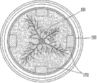
图4是盆栽部分的横截面图。Fig. 4 is a cross-sectional view of a potted plant portion.
图5及图6是示出根据本发明的盆栽的其他例的截面图。5 and 6 are cross-sectional views showing other examples of potted plants according to the present invention.
图7至图10是示出根据本发明的盆栽的其他另一例的图面,其中,图7是盆栽的正截面图,图8是盆栽的俯视图,图9是盆栽的仰视图,图10是示出上下层叠两个盆栽的状态的部分侧视图。7 to 10 are diagrams showing other examples of potted plants according to the present invention, wherein, Fig. 7 is a front sectional view of potted plants, Fig. 8 is a top view of potted plants, Fig. 9 is a bottom view of potted plants, and Fig. 10 is A partial side view showing a state where two potted plants are stacked one above the other.
图11是示出为使用根据本发明的盆栽而利用托盘的状态的概念图。Fig. 11 is a conceptual diagram showing a state in which a tray is used for using a potted plant according to the present invention.
图12是示出为了容易固定根据本发明的岩棉而具有固定单元的盆栽的正截面图。12 is a front sectional view showing a potted plant having a fixing unit for easy fixing of rock wool according to the present invention.
图13是示出为了容易固定根据本发明的岩棉而具有固定单元的盆栽的横截面图。13 is a cross-sectional view showing a potted plant having a fixing unit for easy fixing of rock wool according to the present invention.
图14是示出根据本发明的无动力盆栽栽培系统的其他例的概念图。Fig. 14 is a conceptual diagram showing another example of the unpowered potted cultivation system according to the present invention.
图15是示出根据本发明的无动力灌水及施肥装置的其他例的截面图。Fig. 15 is a cross-sectional view showing another example of the passive watering and fertilizing device according to the present invention.
图16是示出根据本发明的无动力灌水及施肥装置的其他另一例的截面图。Fig. 16 is a sectional view showing another example of the passive watering and fertilizing device according to the present invention.
图17是示出根据本发明的无动力灌水及施肥装置的其他另一例的截面图。Fig. 17 is a sectional view showing another example of the passive watering and fertilizing device according to the present invention.
图18是图17的A部分的放大图。FIG. 18 is an enlarged view of part A of FIG. 17 .
具体实施方式Detailed ways
以下,参照附图详细说明根据本发明的无动力灌水及施肥装置以及利用此装置的无动力盆栽栽培系统。Hereinafter, the non-powered watering and fertilizing device according to the present invention and the non-powered potted cultivation system using the device will be described in detail with reference to the accompanying drawings.
图1是概略示出根据本发明的无动力盆栽栽培系统100的概念图,包括,种植有作物101的盆栽110、水桶以及以无动力方式向盆栽110供应积聚在水桶120的水的无动力灌水及施肥装置150。所述灌水及施肥装置150能够自动向盆栽110供水,从而可适用于如树冠(Canopy)及叶面积宽的果树(例如:葡萄、猕猴桃等)等每天需要大量水的作物。葡萄、猕猴桃等可以提供宽的树荫面积(10m2以上/株),因此,有利于城市的绿化,还能阻止热岛现象,最终有利于防止全球温暖化。设置场所方面,所述盆栽栽培系统100可适用在难以管理水的家庭、建筑物的屋顶、停车场、街道、城市公园、广场或休息场所等。例如,在城市内的混凝土或柏油上栽培树冠宽的藤蔓果树作物500万株(葡萄10m2/株)时,整体树荫面积为5000万m2,因此在夏天能够充分提供树荫。1 is a conceptual diagram schematically showing a non-powered potted plant cultivation system 100 according to the present invention, including a
水桶120可根据作物101的水消耗周期及管理人的条件制作为多种容量。形状上水桶120具备标准的形态,从而可容易用装满水的水桶及时替换使用完的水桶。The
图2是示出根据本发明的无动力灌水及施肥装置的一结构的截面图,图3是图2的无动力灌水及施肥装置的动作状态图,图3是盆栽部分的横截面图。Fig. 2 is a sectional view showing a structure of the non-powered watering and fertilizing device according to the present invention, Fig. 3 is an action state diagram of the non-powered watering and fertilizing device of Fig. 2 , and Fig. 3 is a cross-sectional view of a potted plant part.
如图2及图3所示,在无动力灌水及施肥装置150放置种植有作物101的盆栽110和水桶120。在配置方面,盆栽110和水桶120可以相邻接配置或离开预定距离配置。水桶可以形成为围绕盆栽110的形态。作为一例,水桶120可为

盆栽110具有能够填满培养土的空间,其底面具有能够吸收从下部供应的水的多个通孔112。为了提高吸水性,在盆栽110的底面朝水平方向配置第1岩棉层171,在侧壁朝垂直方向配置第2岩棉层172。第2岩棉层172可沿着盆栽110的侧壁朝外围方向形成多个。所述岩棉层(rockwool)可使用建筑材料或工业材料的废弃物,因此,在资源的再利用及污染防止方面非常有用。The
根据图2,无动力灌水及施肥装置150包括框架151,框架151包括用于放置如上所述的盆栽110的盆栽安装部352和可放置水桶120的水桶放置台153。水桶放置台153形成为凹槽形态以便一次性地积聚从安装在水桶120的阀门装置流出的水或营养液。According to FIG. 2 , the non-powered watering and fertilizing
盆栽安装部152也包含能够积聚水或营养液的积水槽154。积满积水槽154的水或营养液形成能够沉浸盆栽110的底面的水位。The
盆栽安装部152和水桶放置台153通过连通流路155互相连接。如图2所示,连通流路155直接形成于框架151,或作为其他例,可形成为连接盆栽安装部152和水桶放置台153的软管或类似的管道形态。如上所述,积聚在水桶放置台153的水移动到盆栽安装部152并积存,积聚在盆栽安装部152的水通过接触水面的盆栽110的底面被吸收。The
盆栽110为了预定地保持积聚在安装部152的积水槽154的水或营养液,灌水及施肥装置150包括水位调节部130。水位调节部130通过打开或关闭安装在水桶120的下部的阀门部,调节积聚在积水槽154的水或营养液的水位,从而以预定深度沉浸盆栽110的底面。支撑盆栽安装部152的盆栽110的部位由多个阶梯部构成,因此,可根据多种盆栽110的具体条件自如地提供水或营养液。The watering and fertilizing
在水桶120的下部具备阀门装置。阀门装置包括阀座132、移动构件140及弹簧133。所述阀门装置可直接形成在水桶主体121,或形成在可拆卸地形成于水桶主体121的盖子131。图2示出了后一例。阀座132可由橡胶或硅胶等软材质而形成以便能够通过移动构件140的接触提供密封力,并可具备直径朝外侧逐渐变窄的倾斜面,以便能够通过水压获得强的密封性。A valve device is provided at the lower part of the
移动构件140的一端位于阀座132内,从而与阀座132一起实现密闭作用,另一端位于水桶120的外侧并形成为按钮的形态。在移动构件140的外侧端部和盖子131之间配置有弹簧133,向移动构件140朝外侧移动的一方向提供弹力。由此,按压移动构件140的另一端时,移动构件140的内侧端部远离阀座132,从而阀座132的开口被开放,解除按压移动构件140的力时,由于弹簧133的作用而使移动构件140朝相反方向移动,从而阀座132的内侧端部关闭阀座132的开口。One end of the moving
水位调节部130通过调节如上所述的阀门装置的打开及关闭,从而将积聚在盆栽安装部152的积水槽154的水或营养液保持预定水位。具体地,水位调节部130可包括浮子161和操作构件162。浮子161形成为可漂浮在积聚于积水槽154的水或营养液的水面。浮子161可由中空的筒体或低密度树脂物质而成,与积水槽154的水面一起上升或下降。The water
根据图3,浮子161通过操作构件162进行连接,操作构件162的一位置通过枢轴163以被约束地设置在框架151。因此,浮子161上升时,操作构件162以枢轴163为中心顺时针方向旋转,相反地,浮子161下降时,操作构件162以枢轴为中心逆时针方向旋转。在操作构件162的端部设置有按压所述移动构件140的外侧端部141或解除按压的按压构件164。操作构件162朝逆时针方向旋转时,按压构件164按压移动构件140的外侧端部141而开放阀门装置,相反地,操作构件162朝顺时针方向旋转时,解除按压构件164按压移动构件140的外侧端部的力,通过弹簧133的弹力关闭阀门装置(参照图2及图3)。According to FIG. 3 , the
如上所述,通过水位调节部130的作用,积聚在水桶120的水或营养液在盆栽安装部152的积水槽154保持预定水位。因此,供应到盆栽110的水可按照盆栽110的状态持续进行无人管理。As mentioned above, through the function of the water
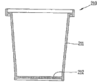
图5及图6是示出根据本发明的其他例的截面图。如图所示,盆栽可由图5的固定式构成或图6的移动式构成。即,如图5所示,固定式盆栽210是在盆栽主体211的下部形成有用于吸收或排放水及营养液的通孔212的单纯主体,而图6的移动式的盆栽210`在盆栽主体211`的下面一侧具备至少一对轮子213。因此,能够容易以朝具有轮子213侧倾斜的状态移动盆栽210`。5 and 6 are cross-sectional views showing other examples according to the present invention. As shown in the figure, the potted plant can be composed of the fixed type in FIG. 5 or the mobile type in FIG. 6 . That is, as shown in Figure 5, the fixed
图7至图10是示出根据本发明的盆栽的其他另一例的图面,其中,图7是盆栽的正截面图,图8是盆栽的俯视图,图9是盆栽的仰视图,图10是示出上下层叠两个盆栽的状态的部分侧视图。7 to 10 are diagrams showing other examples of potted plants according to the present invention, wherein, Fig. 7 is a front sectional view of potted plants, Fig. 8 is a top view of potted plants, Fig. 9 is a bottom view of potted plants, and Fig. 10 is A partial side view showing a state where two potted plants are stacked one above the other.
如图所示,盆栽310为了容易搬运及管理而被标准化。即,盆栽310大体由四边形构成,为了搬运在上端的预定地方设置有手柄315,下端部为了方便层叠而设置有插入槽316。手柄315可设置在4个地方以便多人搬运或机械工作时容易保持均衡。插入槽316形成为可插入于其他盆栽主体311的上端边缘。As shown in the figure, potted
盆栽310的底面为了容易排水而形成为网状318,为了加强底面强度,在中间部分形成有加强架317。The bottom surface of the
所述盆栽310按照容量或大小,优选形成为各种种类。The
如此被标准化的盆栽310可以减低开垦地等用于形成大规模果树园的费用及时间,能够提供均匀的品质和数量。The
图11是示出为使用本发明的盆栽而利用托盘的状态的概念图。Fig. 11 is a conceptual diagram showing a state in which a tray is used for using the potted plant of the present invention.
通过图7至图10说明的盆栽可以构成为多个盆栽成组而层积在一个托盘P上。为此,托盘P包括多个盆栽安装部352,为了一次容易移动层积的盆栽310,而可以形成有叉车槽358。而且,盆栽安装部352连接于所述的无动力灌水及施肥装置即可向盆栽310供应水或营养液。The potted plants described with reference to FIGS. 7 to 10 may be configured so that a plurality of potted plants are stacked on one tray P in groups. Therefore, the tray P includes a plurality of pot
托盘P根据容量可以具有大型、中型、小型等规格,各规格可以层积对应的盆栽。The tray P can have specifications such as large, medium, and small according to capacity, and corresponding potted plants can be stacked in each specification.
在托盘P层积盆栽后通过塑料薄膜等包装手段进行包装而可以大量搬运。After the tray P is stacked and potted, it can be packaged by packaging means such as plastic film and can be transported in large quantities.
如所述构成时,在工厂等将已填满培养土及植栽的各盆栽层积在托盘后,利用搬运车搬运到开垦地并卸载即可管理,非常有用,因此能够大幅度减低形成果树园的时间及费用。When configured as described above, it is very useful to stack each potted plant filled with cultivation soil and planted on a tray in a factory, etc., and then transport it to a reclamation site with a truck and unload it for management. Therefore, it is possible to greatly reduce the formation of fruit trees. Garden time and costs.
图12及图13分别示出为了容易固定根据本发明的岩棉而具有固定单元的盆栽的正截面图及横截面图。12 and 13 respectively show a front sectional view and a cross-sectional view of a potted plant having a fixing unit for easy fixing of rock wool according to the present invention.
为了提高盆栽410的吸水性及保水性,在盆栽410内可以设置岩棉。所述岩棉可以包括朝水平方向配置在盆栽410的底面的第一岩棉471和由垂直方向的柱形形成的第二岩棉472。此时,在盆栽410填满培养土的过程中,为了防止第二岩棉472脱离应安装的位置,在盆栽410的内侧壁配置固定第二岩棉472的支架419。支架419可以形成为夹子或环形。In order to improve the water absorption and water retention of the
图14是示出根据本发明的无动力盆栽栽培系统的其他例的概念图。为了解决在每个盆栽安装水桶并替换的问题,可以构成为成组的多个盆栽通过一个水桶供应水。即,如图14所示,本实施例所示的无动力盆栽栽培系统500包括设有积水槽的多个盆栽安装部552a、552b、552c,盆栽安装部552a、552b、552c的各积水槽通过连接流路580互相连接。各盆栽安装部552a、552b、552c具备水位调节部550以便能够预定地保持积水槽的水位。水位调节部550构成为能够调节通过连接流路580供应的水或营养液的水位,适用图2及图3中的水位调节部的构成。Fig. 14 is a conceptual diagram showing another example of the unpowered potted cultivation system according to the present invention. In order to solve the problem of installing and replacing each potted plant with a water bucket, a plurality of potted plants in groups can be formed to supply water through a water bucket. That is, as shown in FIG. 14 , the non-powered potted
水位调节装置具备一个设有浮子等的大水桶520,在每个盆栽510A、510B、510C具有连接流路及落水槽,但本发明并不限定于此,也可以构成为在每个盆栽510A、510B、510C设置浮子等的结构。The water level adjusting device is provided with a
通过在水桶放置台553放置大容量水桶520,从而对多个盆栽510A、510B、510C可以一起供应水及营养液。By placing the large-
图15是示出根据本发明的无动力灌水及施肥装置的其他例的截面图。Fig. 15 is a cross-sectional view showing another example of the passive watering and fertilizing device according to the present invention.
图15所示的无动力灌水及施肥装置650还包括预定地保持供应给盆栽111的水或营养液的水位的其他技术原理。即,本实施例中所包含的无动力灌水及施肥装置650包括结合于水桶121的盖子631,在盖子631包括阀门装置和水位调节部630。The non-powered watering and fertilizing
阀门装置121包括形成水桶121的开口的阀座132、移动构件140及弹性构件133。移动构件140,其一端位于阀座132内,可以与阀座132一起做密封作用,另一端位于水桶121的外侧,形成为按钮形态。在移动构件140的外侧端部141和盖子631之间配置有弹簧133,从而向移动构件140朝外侧移动的方向受弹力。由此,若按压移动构件140的外侧端部141,则移动构件140的内侧端部从阀座132远离,而开放阀座132的开口,若解除按压移动构件140的力,则通过弹簧133的作用,朝反方向移动移动构件140,从而封闭阀座132的开口。The
水位调节部630包括在弹簧133的周围从盖子631延长预定长度的裙部645,裙部645的至少一侧包括开放孔646。开放孔646是供周围的空气流入水桶141的内部的通道。若水位高于开放孔645,则空气不能通过开放孔646进入水桶121的内部,相反,水位低于开放孔646时,空气可通过开放孔646进入水桶121的内部。水位低于开放孔时,即便有水桶内的水压(重力)作用,也通过形成在水桶的上部空间的真空保持力平衡,而水不会流出到水桶121的外部。因此,通过开放孔646和水位之差以及水桶121内的真空和水桶内的水的重力的平衡关系保持预定水位。The
水桶121,在使用时有必要将其内部保持真空状态,但是,向水桶121内补充水时不能保持真空状态。为此,可以构成为使按压移动构件140的外侧端部141的突出部663任意下降而移动构件140能够堵住阀座132。以此方法,可以通过凸轮装置667构成突出部664,在外部朝一方向旋转杠杆668时,突出部664下降,朝相反方向旋转时,突出部664上升,从而从阀座132开放移动构件140。并在水桶补充水时,可以通过调节所述突出部664来防止水被倒出。The
图16是示出根据本发明的无动力灌水及施肥装置的其他另一例的截面图。Fig. 16 is a sectional view showing another example of the passive watering and fertilizing device according to the present invention.
根据图16,灌水及施肥装置750包括阀门部730及水位调节部740,通过组合阀门部和水位调节部,盆栽能够预定地保持积聚在盆栽安装部152的积水槽154的水或营养液的水位。According to Fig. 16, the watering and fertilizing
阀门部730形成在水桶120的下部。阀门部730包括阀门主体731和移动构件732。The
阀门主体731贯穿水桶120的下部而配置,可拆卸地形成在水桶主体721。但,本发明并不限定于此,可以配置在水桶120的其他位置或可以直接形成在水桶主体721。The valve
阀门主体731例如可以由合成树脂或合金等在水中不生锈的材料形成。并且,阀门主体731形成为圆形,也可以朝上部直径逐渐变小的方向倾斜以便减少水压的影响。The valve
阀门主体731,在其内部形成有通孔733。即,在阀门主体731形成通过通孔733从水桶120排放水或营养液的排出口734。The valve
移动构件732配置在通孔733,一端堵住排出口734。更具体而言,移动构件732的一端位于通孔733内,而与通孔733的一端(通孔形状的面的一端)一起做密封作用。The moving
通过此结构,由于在水桶120内没有妨碍流入到排出口734的水或营养液的流动的要素,因此能够更加顺利地供应水或营养液。With this configuration, since there is no element in the
移动构件732的一端和通孔733的一端形成为互相对应的倾斜面以便增加接触面积。并且,在移动构件732的一端可形成由橡胶或硅胶等构成的软质构件(省略图示)以便与通孔733的一端接触而提供更强的密封力。One end of the moving
移动构件732通过朝水桶120的外部方向移动而可以开放排出口734。由于水桶120的水压,移动构件732通常朝开放排出口734的方向移动,但是会保持适当重量以便在水桶120内的水压较弱时也容易移动。作为所述移动构件732的一例,移动构件732可以为针形阀。The moving
如图所示,移动构件732的另一端(堵住排出口的一端的相反端)位于通孔733的外侧。移动构件732的另一端由水位调节部740支撑,通过支撑点的位置变化,移动构件732可在堵住及开放排出口734的状态之间移动As shown in the drawing, the other end of the moving member 732 (the end opposite to the end blocking the discharge port) is located outside the through
水位调节部740被构成为可调节阀门部730的打开或关闭以便能预定地保持积水槽154的水位。更具体而言,水位调节部740按压移动构件732打开或关闭水桶120的排出口,由此,调节积聚在积水槽154的水或营养液的水位,并能够使盆栽110的底面被水沉浸预定深度。The water
例如,水位调节部740包括浮子741、操作构件742以及止动件743。For example, the water
浮子741形成为可以漂浮在积聚在积水槽154的水或营养液的水面。浮子741可由中空的筒体或低密度树脂物质而成,与积水槽154的水面一起上升或下降。The
根据图3,浮子741对操作构件742施加旋转力。更具体而言,操作构件742的一端固定于浮子741,另一端可旋转地连接于阀门主体731。作为可旋转地连接于阀门主体731的例,操作构件742的另一端可枢接于阀门主体731。According to FIG. 3 , the
在阀门主体731的下部形成有由中空体构成的下端突出部735。操作构件742枢接于下端突出部735的一侧壁,并贯穿形成在下端突出部735的另一侧壁的开口向积水槽154延长。A
当浮子741浮到基准水位以上时,使得移动构件732朝堵住排出口734的方向移动,在操作构件742的两端之间支撑移动构件732。操作构件742和移动构件732的支撑点形成在下端突出部735的中空部分。When the
通过此结构,当浮子741与水面一起下降时,操作构件742以枢轴744为中心逆时针方向旋转,相反,当浮子741上升时,操作构件742以枢轴744为中心顺时针方向旋转。With this structure, when the
当操作构件742逆时针方向旋转时,操作构件742和移动构件732的支撑点往后退并开放阀门部730,相反,当操作构件742顺时针旋转时,操作构件742推移动构件732并关闭阀门部730。When the operating
通过如所述的水位调节部740的作用,积聚在水桶120的水或营养液在盆栽安装部152的积水槽154中保持预定水位。因此,在无人的状态下,能够按照盆栽110的状态持续管理供应到盆栽110内的水。并且,水位调节部740仅通过重力及水压打开或关闭阀门部730,因此能够实现有利于环境的无动力灌水及施肥装置。Through the function of the water
根据图3,在操作构件742的旋转路径上配置有止动件743以限制移动构件732向水桶120的外部方向移动的距离。止动件743配置于下端突出部735的开口,垂直于操作构件742的方向突出,并限制操作构件742的旋转。According to FIG. 3 , a
由此,在第一次设置水桶120或清扫积水槽154等时,在积水槽154没有水或营养液时,可以防止移动构件732从通孔733脱离。Thus, when the
根据图3再次说明阀门部730,在阀门主体731的外周面形成安装在水桶120的一面的外围突起736,在所述外围突起736配置密封构件737以密封所述水桶120的贯穿部分。密封构件737例如可以为环形。The
根据图示,在所述阀门主体731的外周面安装拧紧构件738以防阀门主体731挂在水桶120的另一面(安装有外围突起的面的相反面)。例如,在阀门主体731的外周面形成有螺纹,拧紧构件738可以为结合于螺纹的螺母。According to the figure, a tightening
图17是示出根据本发明的无动力灌水及施肥装置的其他另一实施例的截面图,图18是图17的A部分的放大图。图17及图18所示的无动力灌水及施肥装置850包括预定地保持供应给盆栽的水或营养液的水位的其他技术原理。Fig. 17 is a sectional view showing another embodiment of the non-powered watering and fertilizing device according to the present invention, and Fig. 18 is an enlarged view of part A of Fig. 17 . The non-powered watering and fertilizing
根据图示,阀门主体831内的通孔833包括主通孔833a和辅助通孔833b。According to the figure, the through
主通孔833a沿阀门主体831的长度方向形成,移动构件832可滑动地配置在主通孔833a的内部。即,根据图3说明的实施例中,主通孔833a与通孔133(参照图3)类似。The main through
辅助通孔833b从阀门主体831的外表面连通到主通孔833a。辅助通孔833b的作用是当排出口834被异物等堵住时也能灌水。更具体而言,辅助通孔833b连通水桶120的内部空间和主通孔833a。The auxiliary through
移动构件832形成为可开闭辅助通孔833b。例如,在移动构件832的外周面形成橡胶突起839a,橡胶突起839a随着移动构件832的移动沿形成于主通孔833a的导向槽839b滑动。橡胶突起839a可以形成为环形。The moving
在移动构件832堵住水桶120的排出口834的状态下,橡胶突起839a插入于辅助通孔833b的入口。由此,橡胶突起832a可以堵住辅助通孔833b的入口。In a state where the moving
并且,为了限制移动构件832朝圆周方向旋转且引导移动构件832更顺利滑动,在导向槽839b的相反侧可以形成有辅助导向槽839c。Moreover, in order to limit the rotation of the moving
根据附图,在积水槽154配置浮子的部分往外开放。例如,由于豪雨等而盆栽110(参照图2)内积满雨水时,所述雨水会朝积水槽154逆流。当雨水逆流到预定水位以上时,通过被开放的部分,雨水会往外流出。According to the drawing, the part where the float is arranged in the
在积水槽154配置支撑构件862,当浮子841浮到基准水位以上时,所述支撑构件朝所述浮子841的浮力方向支撑所述浮子841以减低施加于操作构件842的力矩。A
支撑构件862例如构成为可以在预定地点支撑浮子841的上部,并且所述支撑构件安装在盆栽安装部152(参照图3)或水桶放置台153,或者可与水桶放置台153形成为一体。The
例如,当雨水等逆流到积水槽154时,积水槽154的水位继续上升,由此,浮子841施加于操作构件842的力更大。由于增加的力,在操作构件842会产生过度的弯矩M,此力减弱操作构件842的耐久性。For example, when rainwater or the like flows back into the
由于支撑构件862在预定地点支撑浮子841的上部,因此,在移动构件832堵住水桶120的排出口834的状态下,积水槽154的水位继续上升时抵消浮子841的浮力,藉此可以减低对浮子841及操作构件842的外部冲击。Since the supporting
如上所述,虽参照附图说明了无动力灌水、施肥装置及利用此装置的无动力盆栽栽培系统,但是本发明并不限定于本说明书所记载的实施例及图面。可以组合所记载的实施例的一个以上,即,本领域的技术人员可在本发明的技术思想范围内进行各种变形。As mentioned above, although the non-powered irrigation and fertilization device and the non-powered pot cultivation system using the device have been described with reference to the drawings, the present invention is not limited to the embodiments and drawings described in this specification. One or more of the described embodiments can be combined, that is, various modifications can be made by those skilled in the art within the scope of the technical idea of the present invention.
工业利用可能性Possibility of industrial use
无动力灌水、施肥装置及利用此装置的无动力盆栽栽培系统具有工业利用可能性。The non-power irrigation and fertilization device and the non-power potted cultivation system using the device have the possibility of industrial application.
Claims (15)
Applications Claiming Priority (9)
| Application Number | Priority Date | Filing Date | Title |
|---|---|---|---|
| KR1020100055032A KR100981598B1 (en) | 2010-06-10 | 2010-06-10 | Fertigation apparatus operatable without power for pot cultivation |
| KR10-2010-0055032 | 2010-06-10 | ||
| KR1020100079958A KR101106130B1 (en) | 2010-08-18 | 2010-08-18 | Powerless irrigation and nutrient solution |
| KR1020100079959A KR101106131B1 (en) | 2010-08-18 | 2010-08-18 | Non-powered port cultivation system using non-powered watering and nutrient solution |
| KR10-2010-0079958 | 2010-08-18 | ||
| KR10-2010-0079959 | 2010-08-18 | ||
| KR1020100110624A KR101186872B1 (en) | 2010-11-08 | 2010-11-08 | Fertigation apparatus operatable without power for pot cultivation |
| KR10-2010-0110624 | 2010-11-08 | ||
| PCT/KR2010/008769 WO2011155677A1 (en) | 2010-06-10 | 2010-12-08 | Device for unpowered irrigation and fertilization, and unpowered pot cultivation system using same |
Publications (1)
| Publication Number | Publication Date |
|---|---|
| CN102970860A true CN102970860A (en) | 2013-03-13 |
Family
ID=45098258
Family Applications (1)
| Application Number | Title | Priority Date | Filing Date |
|---|---|---|---|
| CN2010800673459A Pending CN102970860A (en) | 2010-06-10 | 2010-12-08 | Non-powered irrigation and fertilization device and non-powered potted cultivation system using the device |
Country Status (5)
| Country | Link |
|---|---|
| US (1) | US20130074405A1 (en) |
| EP (1) | EP2580957A1 (en) |
| JP (1) | JP2013531493A (en) |
| CN (1) | CN102970860A (en) |
| WO (1) | WO2011155677A1 (en) |
Cited By (8)
| Publication number | Priority date | Publication date | Assignee | Title |
|---|---|---|---|---|
| CN105028165A (en) * | 2015-07-29 | 2015-11-11 | 苏州纽东精密制造科技有限公司 | Elasticwater cultivation plant container |
| CN105052713A (en) * | 2015-07-27 | 2015-11-18 | 苏州纽东精密制造科技有限公司 | Double-hole type hydroponic plant container |
| CN106718809A (en) * | 2016-12-29 | 2017-05-31 | 佰仕领骏科技(天津)有限公司 | Environment protection-type hydroponic device |
| CN109089864A (en) * | 2018-09-17 | 2018-12-28 | 吴建清 | A kind of green plant curing means of smart home |
| CN109259530A (en) * | 2018-09-12 | 2019-01-25 | 汪洋 | A kind of water-saving potting laying rack of achievable trickle irrigation |
| CN109819801A (en) * | 2019-03-26 | 2019-05-31 | 杭州余杭弘创物业有限公司 | A kind of indoor intelligent building decoration Decoration flower shelf and its control system |
| CN111685026A (en) * | 2020-07-01 | 2020-09-22 | 宣城知明灯机械设计有限公司 | Long-term business household flower regularly waters device |
| CN120677966A (en) * | 2025-08-11 | 2025-09-23 | 上海海洋大学 | A cultivation method and device for improving the seed germination rate and seedling survival rate of northward-migrating Kandelia candel |
Families Citing this family (9)
| Publication number | Priority date | Publication date | Assignee | Title |
|---|---|---|---|---|
| JP6138461B2 (en) * | 2012-11-19 | 2017-05-31 | サントリーホールディングス株式会社 | Planting equipment |
| US9468166B2 (en) * | 2013-10-04 | 2016-10-18 | Sustainable Products, Llc | Automatic subterranean watering system with refill indicator and gripping mechanism |
| US9295204B2 (en) * | 2013-11-20 | 2016-03-29 | Dung B. Nguyen | Liquid storage and delivery system |
| US10206343B2 (en) * | 2015-10-27 | 2019-02-19 | Ewersmith Enterprises, Llc | Nutrient delivery system |
| CN106561336A (en) * | 2016-11-14 | 2017-04-19 | 南宁市浩发科技有限公司 | Water-storing and waterlogging preventing watermelon seedling culturing pot |
| CN106691025B (en) * | 2016-12-22 | 2018-01-23 | 深圳市大业园林建设有限公司 | A kind of Intelligent potting frame |
| ZA201708364B (en) * | 2017-03-16 | 2018-11-28 | Desert Blooms LLC | Cultivation of crops |
| CN206958371U (en) * | 2017-05-18 | 2018-02-02 | 洪志平 | Water Level Controller for Hydroponic Cultivation System |
| EP4064825A4 (en) * | 2019-11-26 | 2023-09-20 | Invertigro Pty Ltd | Fast filling and draining valve assembly and associated system |
Citations (10)
| Publication number | Priority date | Publication date | Assignee | Title |
|---|---|---|---|---|
| JPH0837962A (en) * | 1994-08-01 | 1996-02-13 | Infuritsuji Kogyo Kk | Container for plant cultivation |
| WO2002042669A1 (en) * | 2000-11-27 | 2002-05-30 | Autogrow Pty Ltd | Float valve |
| WO2003020011A1 (en) * | 2001-09-05 | 2003-03-13 | Franc Gergek | Method and apparatus for watering potted plants |
| CN1414312A (en) * | 2001-10-22 | 2003-04-30 | 北京亚都科技股份有限公司 | Ultrasonic cleaning humidifier |
| EP1310158A1 (en) * | 1999-07-12 | 2003-05-14 | Tsutomu Nagoya | Automatic water feed device for flowerpot |
| JP2003259735A (en) * | 2002-03-12 | 2003-09-16 | Tsutomu Nagoya | Bottom water supply type water supply device for flower pot |
| KR20030094963A (en) * | 2002-06-11 | 2003-12-18 | 주식회사 셀그린 | flowerpot for supply water automatically |
| CN1771787A (en) * | 2005-11-17 | 2006-05-17 | 郑琪 | Automatic flower pot watering device |
| CN201274694Y (en) * | 2008-10-17 | 2009-07-22 | 白桂桃 | Automatic water-compensating device |
| CN201365437Y (en) * | 2008-11-02 | 2009-12-23 | 倪国森 | Micro-irrigation device |
Family Cites Families (6)
| Publication number | Priority date | Publication date | Assignee | Title |
|---|---|---|---|---|
| JPH05137468A (en) * | 1991-11-19 | 1993-06-01 | Brother Ind Ltd | Automatic watering system for tabletop plant cultivation |
| JPH077395U (en) * | 1993-07-08 | 1995-02-03 | 有限会社松村精機 | Automatic water supply system for flower pots |
| JP2000333544A (en) * | 1999-05-25 | 2000-12-05 | Nagoya Tsutomu | Water tank equipped with automatic water supply device for plant cultivation |
| KR200404231Y1 (en) * | 2005-08-08 | 2005-12-20 | 주식회사 제이앤제이통상 | A flower pot for being supplied water automatically |
| JP2010068735A (en) * | 2008-09-17 | 2010-04-02 | Kesao Sakizaki | Automatically watering planter |
| JP3152201U (en) * | 2009-05-11 | 2009-07-23 | カミマル株式会社 | Planter water supply equipment |
-
2010
- 2010-12-08 EP EP10852959.5A patent/EP2580957A1/en not_active Withdrawn
- 2010-12-08 CN CN2010800673459A patent/CN102970860A/en active Pending
- 2010-12-08 JP JP2013514092A patent/JP2013531493A/en active Pending
- 2010-12-08 US US13/703,073 patent/US20130074405A1/en not_active Abandoned
- 2010-12-08 WO PCT/KR2010/008769 patent/WO2011155677A1/en not_active Ceased
Patent Citations (10)
| Publication number | Priority date | Publication date | Assignee | Title |
|---|---|---|---|---|
| JPH0837962A (en) * | 1994-08-01 | 1996-02-13 | Infuritsuji Kogyo Kk | Container for plant cultivation |
| EP1310158A1 (en) * | 1999-07-12 | 2003-05-14 | Tsutomu Nagoya | Automatic water feed device for flowerpot |
| WO2002042669A1 (en) * | 2000-11-27 | 2002-05-30 | Autogrow Pty Ltd | Float valve |
| WO2003020011A1 (en) * | 2001-09-05 | 2003-03-13 | Franc Gergek | Method and apparatus for watering potted plants |
| CN1414312A (en) * | 2001-10-22 | 2003-04-30 | 北京亚都科技股份有限公司 | Ultrasonic cleaning humidifier |
| JP2003259735A (en) * | 2002-03-12 | 2003-09-16 | Tsutomu Nagoya | Bottom water supply type water supply device for flower pot |
| KR20030094963A (en) * | 2002-06-11 | 2003-12-18 | 주식회사 셀그린 | flowerpot for supply water automatically |
| CN1771787A (en) * | 2005-11-17 | 2006-05-17 | 郑琪 | Automatic flower pot watering device |
| CN201274694Y (en) * | 2008-10-17 | 2009-07-22 | 白桂桃 | Automatic water-compensating device |
| CN201365437Y (en) * | 2008-11-02 | 2009-12-23 | 倪国森 | Micro-irrigation device |
Cited By (9)
| Publication number | Priority date | Publication date | Assignee | Title |
|---|---|---|---|---|
| CN105052713A (en) * | 2015-07-27 | 2015-11-18 | 苏州纽东精密制造科技有限公司 | Double-hole type hydroponic plant container |
| CN105028165A (en) * | 2015-07-29 | 2015-11-11 | 苏州纽东精密制造科技有限公司 | Elasticwater cultivation plant container |
| CN106718809A (en) * | 2016-12-29 | 2017-05-31 | 佰仕领骏科技(天津)有限公司 | Environment protection-type hydroponic device |
| CN109259530A (en) * | 2018-09-12 | 2019-01-25 | 汪洋 | A kind of water-saving potting laying rack of achievable trickle irrigation |
| CN109089864A (en) * | 2018-09-17 | 2018-12-28 | 吴建清 | A kind of green plant curing means of smart home |
| CN109819801A (en) * | 2019-03-26 | 2019-05-31 | 杭州余杭弘创物业有限公司 | A kind of indoor intelligent building decoration Decoration flower shelf and its control system |
| CN111685026A (en) * | 2020-07-01 | 2020-09-22 | 宣城知明灯机械设计有限公司 | Long-term business household flower regularly waters device |
| CN111685026B (en) * | 2020-07-01 | 2022-07-08 | 宣城知明灯机械设计有限公司 | A kind of flower timing watering device for long-term business trip family |
| CN120677966A (en) * | 2025-08-11 | 2025-09-23 | 上海海洋大学 | A cultivation method and device for improving the seed germination rate and seedling survival rate of northward-migrating Kandelia candel |
Also Published As
| Publication number | Publication date |
|---|---|
| EP2580957A1 (en) | 2013-04-17 |
| US20130074405A1 (en) | 2013-03-28 |
| WO2011155677A1 (en) | 2011-12-15 |
| JP2013531493A (en) | 2013-08-08 |
Similar Documents
| Publication | Publication Date | Title |
|---|---|---|
| JP2013531493A (en) | Non-powered irrigation and nutrient solution apparatus and non-powered pot cultivation system using the same | |
| KR102018059B1 (en) | Smart Planter System Having Reduction Function Fine Dust and Surface Temperature | |
| KR101282231B1 (en) | Fertigation apparatus operatable without power for plant cultivation system | |
| WO2007063815A1 (en) | Plant cultivating unit and plant cultivating container | |
| CN206728773U (en) | A kind of Landscape water-saving irrigation system | |
| CN107182620A (en) | Drip irrigation type agricultural greenhouse system and greenhouse gardening method | |
| CN105248176A (en) | Roof greening planting container | |
| CN205161412U (en) | Watering planting system | |
| CN201182113Y (en) | Arc-shaped automatic water supply and fertilizer flower box | |
| CN103141361B (en) | Anti-clogging capillary drip irrigation emitter with flat plate superimposition structure | |
| CN205161271U (en) | Roof greening plants container | |
| CN206909346U (en) | From irrigation landscape water-storing device | |
| CN101893312B (en) | Air conditioner greening and cooling device utilizing condensed water | |
| CN105165551A (en) | Water storage irrigation and energy saving park | |
| CN104429864A (en) | Method for cultivating crops on roof | |
| CN220545533U (en) | A three-dimensional planting device that facilitates irrigation | |
| KR101106131B1 (en) | Non-powered port cultivation system using non-powered watering and nutrient solution | |
| CN206866199U (en) | External mounting type cylindrical drip irrigation tube and agricultural greenhouse system | |
| CN206791189U (en) | External mounting type flow is adjustable cylindrical drip irrigation tube and agricultural greenhouse system | |
| CN113529853B (en) | A water recycling system for garden landscape | |
| CN203361237U (en) | Landscape greening combined-type roof rainwater comprehensive utilization system | |
| CN202697326U (en) | Plant cultivation container | |
| CN116058212A (en) | Rainwater regulation irrigation facility | |
| CN209030795U (en) | A kind of novel plant matrix culture device | |
| CN202153916U (en) | Ecological water-saving type multi-functional tree stump |
Legal Events
| Date | Code | Title | Description |
|---|---|---|---|
| C06 | Publication | ||
| PB01 | Publication | ||
| C10 | Entry into substantive examination | ||
| SE01 | Entry into force of request for substantive examination | ||
| C02 | Deemed withdrawal of patent application after publication (patent law 2001) | ||
| WD01 | Invention patent application deemed withdrawn after publication |
Application publication date: 20130313 |