CN102946108A - Voltage automatic compensation device - Google Patents
Voltage automatic compensation device Download PDFInfo
- Publication number
- CN102946108A CN102946108A CN2012104747306A CN201210474730A CN102946108A CN 102946108 A CN102946108 A CN 102946108A CN 2012104747306 A CN2012104747306 A CN 2012104747306A CN 201210474730 A CN201210474730 A CN 201210474730A CN 102946108 A CN102946108 A CN 102946108A
- Authority
- CN
- China
- Prior art keywords
- phase
- compensation
- line
- voltage
- contactor
- Prior art date
- Legal status (The legal status is an assumption and is not a legal conclusion. Google has not performed a legal analysis and makes no representation as to the accuracy of the status listed.)
- Pending
Links
Images

Classifications
-
- Y—GENERAL TAGGING OF NEW TECHNOLOGICAL DEVELOPMENTS; GENERAL TAGGING OF CROSS-SECTIONAL TECHNOLOGIES SPANNING OVER SEVERAL SECTIONS OF THE IPC; TECHNICAL SUBJECTS COVERED BY FORMER USPC CROSS-REFERENCE ART COLLECTIONS [XRACs] AND DIGESTS
- Y02—TECHNOLOGIES OR APPLICATIONS FOR MITIGATION OR ADAPTATION AGAINST CLIMATE CHANGE
- Y02E—REDUCTION OF GREENHOUSE GAS [GHG] EMISSIONS, RELATED TO ENERGY GENERATION, TRANSMISSION OR DISTRIBUTION
- Y02E40/00—Technologies for an efficient electrical power generation, transmission or distribution
- Y02E40/30—Reactive power compensation
Landscapes
- Control Of Electrical Variables (AREA)
- Supply And Distribution Of Alternating Current (AREA)
Abstract
本发明公开了一种电压自动补偿装置,涉及供电系统无功补偿优化配置装置技术领域。包括箱体,所述装置的输入端经接线端子与自动补偿控制器的输入端连接,自动补偿控制器的输出端与三相分补复合开关的控制端连接,三相分补复合开关与三相分补电容器C1连接,自动补偿控制器的输出端与接触器的控制端连接,接触器与三相共补电容器C2连接,A相线、B相线、C相线和零线N经接线端子分别与三相分补复合开关和接触器连接。所述装置能够对低压线路无功负荷进行有效地补偿,提高了线路电压,同时解决了三相负荷不平衡的问题,从而提高了功率因数,减少了电能损失。
The invention discloses an automatic voltage compensation device and relates to the technical field of reactive power compensation optimization configuration devices for power supply systems. Including the box, the input end of the device is connected to the input end of the automatic compensation controller through the terminal, the output end of the automatic compensation controller is connected to the control end of the three-phase split-compensation composite switch, and the three-phase split-compensation composite switch is connected to the three-phase The phase-splitting compensation capacitor C1 is connected, the output terminal of the automatic compensation controller is connected to the control terminal of the contactor, the contactor is connected to the three-phase common compensation capacitor C2, and the A-phase line, B-phase line, C-phase line and neutral line N are connected through The terminals are respectively connected with the three-phase split-compensation composite switch and the contactor. The device can effectively compensate the reactive load of the low-voltage line, increase the line voltage, and simultaneously solve the problem of unbalanced three-phase load, thereby improving the power factor and reducing the loss of electric energy.
Description
技术领域 technical field
本发明涉及供电系统无功补偿优化配置装置技术领域,尤其涉及一种电压自动补偿装置。 The invention relates to the technical field of reactive power compensation optimization configuration devices for power supply systems, in particular to an automatic voltage compensation device.
背景技术 Background technique
当前,随着空调、冰箱、电磁炉等大功率家用电器的迅速普及,居民用电以年均20%~30%的速度递增。快速增加的居民用电态势,使低压线路末端电压逐渐偏低的问题日益严重,给广大用电客户带来了极大的不便,也给供电企业的优质服务带来了极大的挑战,低电压已成为当前电力客户普遍关注的焦点。 At present, with the rapid popularization of high-power household appliances such as air conditioners, refrigerators, and induction cookers, residents' electricity consumption is increasing at an average annual rate of 20% to 30%. The rapidly increasing situation of residential electricity consumption has made the problem of gradually low voltage at the end of low-voltage lines increasingly serious, which has brought great inconvenience to the majority of electricity customers and also brought great challenges to the high-quality services of power supply companies. Voltage has become the focus of general attention of current power customers.
为了解决低压线路末端电压过低的问题,过去常采用传统低压无功补偿装置,该装置安装于配变首端,对线路进行无功集中补偿,该补偿装置仅补偿了配变及10千伏高压线路无功负荷,属于中间无功补偿,而低压用电设备的无功负荷仍通过低压线路供到用电设备上,无法解决低电压线路中因无功负荷存在导致的电压损失大、线损率高的问题,也无法解决低压线路后端低电压问题。 In order to solve the problem of low voltage at the end of low-voltage lines, traditional low-voltage reactive power compensation devices were often used in the past. The reactive load of the high-voltage line belongs to the intermediate reactive power compensation, and the reactive load of the low-voltage electrical equipment is still supplied to the electrical equipment through the low-voltage line, which cannot solve the problem of large voltage loss caused by the existence of reactive load in the low-voltage line. The problem of high loss rate cannot solve the problem of low voltage at the back end of the low-voltage line.
另一方面,供电企业主要通过新装配变或增大低压导线线径的措施,解决低电压问题。但新装配变投资大,周期长,线路走廊和占地问题协调难;增大低压导线线径也因低压线路往往沿墙架设而处处受阻,低电压问题难以快速解决。另外随着用电负荷不断增加,无功负荷迅速增大,导致低压线损率居高不下,严重影响供电企业的经济效益,甚至社会效益。 On the other hand, power supply companies mainly solve the low-voltage problem through new assembly changes or measures to increase the diameter of low-voltage wires. However, the new assembly requires a large investment and a long cycle, and it is difficult to coordinate line corridors and land occupation issues; increasing the diameter of low-voltage wires is also hindered everywhere because low-voltage lines are often erected along the wall, and the low-voltage problem is difficult to solve quickly. In addition, as the power load continues to increase, the reactive power load increases rapidly, resulting in a high low-voltage line loss rate, which seriously affects the economic and even social benefits of power supply companies.
在对用电市场进行调查研究,发现存在大量单相负荷的低压供配电系统中,由于负荷变化的随机性,导致三相负载的严重不平衡,例如楼宇及住宅小区等民用建筑的低压供配电系统中,由于存在有大量的单相负荷(如照明灯具、家用电器、办公设备、计算机等),且该类负荷使用的随机性极高,使原本通过调配供电回路的负荷来实现的三相平衡在实际运行中已全无意义,导致了低压供配电系统三相负载阶段性的严重不平衡。这种不平衡不具备规律性,无法事先预知,也无法有效地改善。再加上每相负载的功率因数也不尽相同,便常常使得每相回路中需要补偿的无功功率差异很大,要利用传统的三相共补同投同切无功补偿方式难以对系统无功负荷进行有效地补偿,也无法解决三相负荷不平衡的问题,而全部采用单相补偿则投资较大。 In the investigation and research of the electricity market, it is found that in the low-voltage power supply and distribution system with a large number of single-phase loads, the randomness of the load change will lead to a serious imbalance of the three-phase load, such as the low-voltage power supply of civil buildings such as buildings and residential quarters. In the power distribution system, due to the existence of a large number of single-phase loads (such as lighting fixtures, household appliances, office equipment, computers, etc.) The three-phase balance is completely meaningless in actual operation, which leads to the serious unbalance of the three-phase load of the low-voltage power supply and distribution system in stages. This imbalance has no regularity, cannot be predicted in advance, and cannot be effectively improved. In addition, the power factor of each phase load is also different, which often makes the reactive power to be compensated in each phase circuit very different. Effective compensation of reactive loads cannot solve the problem of unbalanced three-phase loads, and all single-phase compensations require a large investment.
发明内容 Contents of the invention
本发明所要解决的技术问题是提供一种电压自动补偿装置,能够自动补偿低压线路上的相电压,提高了功率因数,减少了电能损耗。 The technical problem to be solved by the present invention is to provide an automatic voltage compensation device, which can automatically compensate the phase voltage on the low-voltage line, improve the power factor and reduce the power loss.
为解决上述技术问题,本发明所采取的技术方案是:一种电压自动补偿装置,包括箱体,其特征在于自动补偿控制器的输出端与三相分补复合开关的控制端连接,三相分补复合开关与三相分补电容器C1连接,自动补偿控制器的输出端与接触器的控制端连接,接触器与三相共补电容器C2连接,A相线、B相线、C相线和零线N经接线端子分别与三相分补复合开关和接触器连接,电流互感器经接线端子与自动补偿控制器的电流采样端连接,A相线、B相线、C相线和零线N与自动补偿控制器的电压采样端连接,任意一条相线和零线N与自动补偿控制器的电源输入端连接。 In order to solve the above technical problems, the technical solution adopted by the present invention is: an automatic voltage compensation device, including a box, characterized in that the output end of the automatic compensation controller is connected to the control end of the three-phase split-complement composite switch, and the three-phase The split-complement composite switch is connected to the three-phase split-compensation capacitor C1, the output terminal of the automatic compensation controller is connected to the control terminal of the contactor, the contactor is connected to the three-phase common compensation capacitor C2, and the A-phase line, B-phase line, and C-phase line and neutral line N are respectively connected to the three-phase split-compensation composite switch and contactor through the terminal, the current transformer is connected to the current sampling terminal of the automatic compensation controller through the terminal, and the A-phase line, B-phase line, C-phase line and zero Line N is connected to the voltage sampling terminal of the automatic compensation controller, and any phase line and neutral line N are connected to the power input terminal of the automatic compensation controller.
优选的:所述三相分补电容器C1上设有指示灯L1-L3。 Preferably: indicator lamps L1-L3 are provided on the three-phase split-compensation capacitor C1.
优选的:所述三相共补电容器C2上设有指示灯L4。 Preferably: the three-phase co-compensation capacitor C2 is provided with an indicator light L4.
优选的:在所述箱体内设有避雷器。 Preferably: a lightning arrester is provided in the box.
采用上述技术方案所产生的有益效果在于:电流互感器的电流取样信号经接线端子传送到自动补偿控制器,自动补偿控制器再通过三相分补复合开关和接触器来实现对三相分补电容器和三相共补电容器的投切使用。当单相无功负荷升高时,自动补偿控制器通过三相分补复合开关的接通使三相分补电容器投入运行,当单相无功负荷降低时,自动补偿控制器通过三相分补复合开关的断开使三相分补电容器退出运行。如果三相无功负荷都升高且三相分补电容器也都投入运行,补偿容量还达不到补偿要求时,自动补偿控制器通过接触器来实现三相共补电容器的投入运行。这样对低压线路无功负荷进行有效地补偿,提高了线路电压,同时解决了三相负荷不平衡的问题,从而提高了功率因数,减少了电能损失。 The beneficial effect of adopting the above technical scheme is that the current sampling signal of the current transformer is transmitted to the automatic compensation controller through the terminal, and the automatic compensation controller realizes the three-phase compensation through the three-phase compensation composite switch and contactor. Switching and switching of capacitors and three-phase co-compensation capacitors. When the single-phase reactive load increases, the automatic compensation controller puts the three-phase sub-compensation capacitor into operation through the connection of the three-phase sub-compensation composite switch. The disconnection of the composite compensation switch makes the three-phase split compensation capacitor out of operation. If the three-phase reactive loads are all increased and the three-phase sub-compensation capacitors are also put into operation, and the compensation capacity does not meet the compensation requirements, the automatic compensation controller will realize the operation of the three-phase co-compensation capacitors through the contactor. In this way, the reactive load of the low-voltage line is effectively compensated, the line voltage is increased, and the problem of unbalanced three-phase load is solved at the same time, thereby improving the power factor and reducing power loss.
附图说明 Description of drawings
下面结合附图和具体实施方式对本发明作进一步详细的说明。 The present invention will be further described in detail below in conjunction with the accompanying drawings and specific embodiments.
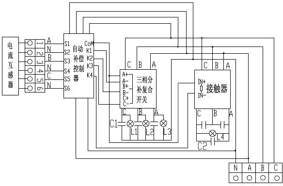
图1是本发明的原理框图。 Fig. 1 is a functional block diagram of the present invention.
具体实施方式 Detailed ways
如图1所示,一种电压自动补偿装置,包括箱体,在所述箱体内设有避雷器,起到防雷作用。自动补偿控制器的输出端与三相分补复合开关的控制端连接,三相分补复合开关与三相分补电容器C1连接,三相分补电容器C1上设有指示灯L1-L3,分别用来指示A、B、C相的分补情况。自动补偿控制器的输出端与接触器的控制端连接,接触器与三相共补电容器C2连接,A相线、B相线、C相线和零线N经接线端子分别与三相分补复合开关和接触器连接,所述三相共补电容器C2上设有指示灯L4,用来显示是否在对A、B、C相进行共补。电流互感器经接线端子与自动补偿控制器的电流采样端连接,A相线、B相线、C相线和零线N与自动补偿控制器的电压采样端连接,任意一条相线和零线N与自动补偿控制器的电源输入端连接。 As shown in FIG. 1 , an automatic voltage compensation device includes a box body, and a lightning arrester is arranged in the box body to play the role of lightning protection. The output end of the automatic compensation controller is connected to the control end of the three-phase split compensation composite switch, and the three-phase split compensation composite switch is connected to the three-phase split compensation capacitor C1, and the three-phase split compensation capacitor C1 is provided with indicator lamps L1-L3, respectively It is used to indicate the distribution and replenishment of A, B, and C phases. The output end of the automatic compensation controller is connected to the control end of the contactor, the contactor is connected to the three-phase common compensation capacitor C2, and the A phase line, the B phase line, the C phase line and the neutral line N are respectively connected to the three-phase sub-compensation The composite switch is connected to the contactor, and the three-phase co-complementing capacitor C2 is provided with an indicator light L4 for displaying whether the co-complementing of phases A, B, and C is being performed. The current transformer is connected to the current sampling terminal of the automatic compensation controller through the terminal, and the A phase line, the B phase line, the C phase line and the neutral line N are connected to the voltage sampling terminal of the automatic compensation controller, and any phase line and neutral line N is connected with the power input terminal of the automatic compensation controller.
自动补偿控制器:通过采集电流互感器信号控制三相分补复合开关和接触器。输入端的接线端子:接电流互感器接线端子。与三相分补控制开关和接触器连接的接线端子接入主线路的零线N、A相线、B相线和C相线。三相分补复合开关控制三相分补电容器的使用,接触器控制三相共补电容器的使用。三相分补电容器可以实现对A相、B相和C相分别进行补偿,三相共补电容器可实现对A相、B相和C相同时进行补偿。 Automatic compensation controller: control the three-phase split-complement composite switch and contactor by collecting the current transformer signal. Connecting terminal of the input terminal: connected to the connecting terminal of the current transformer. The terminal connected with the three-phase split-compensation control switch and the contactor is connected to the neutral line N, A-phase line, B-phase line and C-phase line of the main line. The three-phase split compensation compound switch controls the use of three-phase split compensation capacitors, and the contactor controls the use of three-phase common compensation capacitors. The three-phase split compensation capacitor can realize compensation for phase A, phase B and phase C respectively, and the three-phase common compensation capacitor can realize compensation for phase A, phase B and phase C at the same time.
电流互感器的电流采样信号经接线端子传送到自动补偿控制器,自动补偿控制器再通过三相分补复合开关和接触器来实现对三相分补电容器和三相共补电容器的投切使用。当单相无功负荷升高时,自动补偿控制器通过三相分补复合开关的接通使三相分补电容器投入运行,当单相无功负荷降低时,自动补偿控制器通过三相分补复合开关的断开使三相分补电容器退出运行。如果三相无功负荷都升高且三相分补电容器也都投入运行,补偿容量还达不到补偿要求时,自动补偿控制器通过接触器来实现三相共补电容器的投入运行。 The current sampling signal of the current transformer is transmitted to the automatic compensation controller through the terminal, and the automatic compensation controller realizes the switching and use of the three-phase split compensation capacitor and the three-phase common compensation capacitor through the three-phase split compensation compound switch and contactor . When the single-phase reactive load increases, the automatic compensation controller puts the three-phase sub-compensation capacitor into operation through the connection of the three-phase sub-compensation composite switch. The disconnection of the composite compensation switch makes the three-phase split compensation capacitor out of operation. If the three-phase reactive loads are all increased and the three-phase sub-compensation capacitors are also put into operation, and the compensation capacity does not meet the compensation requirements, the automatic compensation controller will realize the operation of the three-phase co-compensation capacitors through the contactor.
居民用电中三相负荷不平衡是随机出现且无规律可循的,传统的三相共补调整方式会造成单相电压过高或补偿不足;三相负荷调整通常由人工完成,不能实现随负荷变化进行实时调整。自动补偿控制器可通过线路传输的电流信号计算每相功率因数,对低于设定值时进行分相补偿或三相同补或同时补偿。所述装置可以根据负荷(电流)变化实时投切电容器,在接到外部控制信号后,通过逻辑判断,自动寻找最佳投切时间点,达到电压及三相负荷平衡的实时调整,将功率因数保持在最高水平。 The unbalanced three-phase load in residential electricity consumption occurs randomly and has no rules to follow. The traditional three-phase co-compensation adjustment method will cause excessive single-phase voltage or insufficient compensation; three-phase load adjustment is usually done manually, and it cannot be realized Load changes are adjusted in real time. The automatic compensation controller can calculate the power factor of each phase through the current signal transmitted by the line, and perform phase-separated compensation or three-phase compensation or simultaneous compensation when it is lower than the set value. The device can switch capacitors in real time according to load (current) changes. After receiving external control signals, it can automatically find the best switching time point through logical judgment to achieve real-time adjustment of voltage and three-phase load balance. Stay on top level.
所述装置的安全控制措施:1、装置内安装了低压避雷器,保护装置内设备不被雷击产生的过流和过压烧毁。2、三相分补复合开关保证过零投切,无涌流,触点不烧结,能耗小,无谐波注入,大大提高了装置的安全性和可靠性。3、在安全运行方面,为了防止电流互感器安装在低压线路上被雨淋日晒,设计延长电流取样电缆,把电流互感器安装在箱体内部,消除了存在的不安全隐患。 The safety control measures of the device: 1. A low-voltage lightning arrester is installed in the device to protect the equipment in the device from being burned by overcurrent and overvoltage caused by lightning strikes. 2. The three-phase split-complement composite switch ensures zero-cross switching, no inrush current, no contact sintering, low energy consumption, and no harmonic injection, which greatly improves the safety and reliability of the device. 3. In terms of safe operation, in order to prevent the current transformer installed on the low-voltage line from being exposed to rain and sun, the design extends the current sampling cable and installs the current transformer inside the box to eliminate the existing hidden dangers.
所述装置采用先进的自动补偿控制器、三相分补复合开关、电容接触器、三相分补电容器、三相共补电容器及箱体组成。自动补偿控制器可以采用FJK-02型,它具有三相共补、分相补偿、综合补偿功能,可通过菜单进行设置控制方案;三相分补复合开关可以采用ZFK型:是最新一代电容器的投切开关,当接到外部控制信号后,通过逻辑判断,自动寻找最佳投切点,保证过零投切,无涌流,触点不烧结,能耗小、无谐波注入;电容器:采用的是国内最先进的浙江正泰公司生产的BZMJ型三相共补电容器与三相分补偿电容器;箱体:采用1000*600*400不锈钢材料喷塑配电箱,便于在低压线路上安装应用。 The device is composed of an advanced automatic compensation controller, a three-phase split-complement composite switch, a capacitor contactor, a three-phase split-complement capacitor, a three-phase co-complement capacitor and a box. The automatic compensation controller can adopt the FJK-02 type, which has three-phase common compensation, phase-separated compensation, and comprehensive compensation functions, and the control scheme can be set through the menu; the three-phase split compensation composite switch can adopt the ZFK type: it is the latest generation of capacitors. The switching switch, after receiving the external control signal, automatically finds the best switching point through logical judgment to ensure zero-crossing switching, no inrush current, no sintering of contacts, low energy consumption, and no harmonic injection; capacitor: adopt The most advanced BZMJ three-phase common compensation capacitor and three-phase sub-compensation capacitor produced by Zhejiang Chint Company in China; box body: 1000*600*400 stainless steel material spray distribution box, easy to install and apply on low-voltage lines.
所述装置适用于所有低压线路末端电压低的台区,尤其是以居民生活用电为主的三相负荷不平衡的台区。适用于无线路改造计划但亟需解决低电压问题的台区。可安装在低压线路末端大负荷前端电杆上,安装时选一个合适的耐张杆,将引线断开,利用电缆穿过电流互感器连接线路,再从电流互感器二次接线到自动补偿控制器来控制电容器的投切。安装完成后,根据现场情况,在自动补偿控制器中设置每相电压、每相功率因数、投切延时、过压欠压保护时间等数值,即可实现自动根据电压和功率因数投切电容器,调整电压及平衡三相负荷。 The device is suitable for all station areas with low terminal voltage of low-voltage lines, especially the station area with unbalanced three-phase load mainly for residential electricity consumption. It is suitable for the station area without a line reconstruction plan but urgently needs to solve the low voltage problem. It can be installed on the pole at the front end of the low-voltage line with heavy load. When installing, choose a suitable tension pole, disconnect the lead wire, use the cable to pass through the current transformer to connect the line, and then connect the secondary wiring of the current transformer to the automatic compensation control device to control the switching of capacitors. After the installation is completed, according to the site conditions, set the values of each phase voltage, each phase power factor, switching delay, overvoltage and undervoltage protection time, etc. in the automatic compensation controller, and then automatically switch capacitors according to the voltage and power factor. , Adjust the voltage and balance the three-phase load.
安装所述装置现场应用各项功能良好,并取得了良好效果:一方面通过分相补偿及三相共补功能,台区电压一般可提高10-20V,有效改善了低电压情况。另一方面,通过分相补偿,平衡了三相负荷,可将功率因率保持在0.95左右,提高了用电效率,不会出现配电变压器单相负荷过高的情况,也不会出现因电压质量引起的投诉。根据运行状况计算,安装“低压分相共补自动补偿器”后,每个台区年节省低压线损金额0.5万元至1.4万元,1年左右即可收回安装成本。 The installation of the device has good functions in field application and has achieved good results: on the one hand, through the phase-separated compensation and three-phase co-compensation functions, the voltage in the station area can generally be increased by 10-20V, which effectively improves the low voltage situation. On the other hand, through phase-separated compensation, the three-phase load is balanced, the power factor ratio can be kept at about 0.95, and the power consumption efficiency is improved. Complaints arising from voltage quality. According to the calculation of the operating conditions, after installing the "low-voltage phase separation and co-compensation automatic compensator", the annual low-voltage line loss of each station area can be saved from 5,000 yuan to 14,000 yuan, and the installation cost can be recovered in about one year.
所述装置的成本主要根据无功补偿容量的大小确定,资金约在0.65-1.0万元左右。便于安装,不影响线路的安全运行,能降低用电成本,同时也大大缓解了线路改造资金不足的压力。这样对低压线路无功负荷进行有效地补偿,提高了线路电压,同时解决了三相负荷不平衡的问题,从而提高了功率因数,减少了电能损失。改善了低压台区电压质量,提高了配电变压器的承载能力,同时提高用户满意度,降低了因电压质量引起的投诉数量。具有灵活方便,投资小,效率高的特点。 The cost of the device is mainly determined according to the size of the reactive power compensation capacity, and the capital is about 6,500-10,000 yuan. It is easy to install, does not affect the safe operation of the line, can reduce the cost of electricity, and also greatly relieves the pressure of insufficient funds for line renovation. In this way, the reactive load of the low-voltage line is effectively compensated, the line voltage is increased, and the problem of unbalanced three-phase load is solved at the same time, thereby improving the power factor and reducing power loss. The voltage quality of the low-voltage station area has been improved, the carrying capacity of distribution transformers has been increased, user satisfaction has been improved, and the number of complaints caused by voltage quality has been reduced. It has the characteristics of flexibility, convenience, small investment and high efficiency. the
Claims (4)
Priority Applications (1)
| Application Number | Priority Date | Filing Date | Title |
|---|---|---|---|
| CN2012104747306A CN102946108A (en) | 2012-11-21 | 2012-11-21 | Voltage automatic compensation device |
Applications Claiming Priority (1)
| Application Number | Priority Date | Filing Date | Title |
|---|---|---|---|
| CN2012104747306A CN102946108A (en) | 2012-11-21 | 2012-11-21 | Voltage automatic compensation device |
Publications (1)
| Publication Number | Publication Date |
|---|---|
| CN102946108A true CN102946108A (en) | 2013-02-27 |
Family
ID=47729027
Family Applications (1)
| Application Number | Title | Priority Date | Filing Date |
|---|---|---|---|
| CN2012104747306A Pending CN102946108A (en) | 2012-11-21 | 2012-11-21 | Voltage automatic compensation device |
Country Status (1)
| Country | Link |
|---|---|
| CN (1) | CN102946108A (en) |
Cited By (5)
| Publication number | Priority date | Publication date | Assignee | Title |
|---|---|---|---|---|
| CN104836124A (en) * | 2015-04-26 | 2015-08-12 | 成都恒力达科技有限公司 | Capacitor reactive power compensation cabinet |
| CN104993504A (en) * | 2014-10-21 | 2015-10-21 | 中国矿业大学 | Unbalanced load charged commutation apparatus |
| CN105262078A (en) * | 2014-07-18 | 2016-01-20 | 北海市深蓝科技发展有限责任公司 | Stepped active balance and reactive compensation management device for low-voltage transformer area |
| CN106655214A (en) * | 2016-12-29 | 2017-05-10 | 山东民生电气设备有限公司 | Reactive compensation device for power distribution transformer |
| CN108206526A (en) * | 2018-01-22 | 2018-06-26 | 许继电源有限公司 | A kind of capacitor switching partition control method and device |
Citations (8)
| Publication number | Priority date | Publication date | Assignee | Title |
|---|---|---|---|---|
| CN2369394Y (en) * | 1999-04-27 | 2000-03-15 | 时代集团公司 | Automatic intellectual low voltage reactive compensator |
| CN2544452Y (en) * | 2002-06-15 | 2003-04-09 | 乐清市旭日无功动态补偿设备厂 | Low-voltage idle dynamic compensator |
| CN2604809Y (en) * | 2003-02-17 | 2004-02-25 | 重庆电力试验研究所 | Intelligent low-voltage reactive power compensation device |
| CN201393070Y (en) * | 2009-04-23 | 2010-01-27 | 西安秦骊成套电器有限公司 | Low-voltage reactive power comprehensive compensation device |
| CN201766368U (en) * | 2010-04-26 | 2011-03-16 | 南京业基电气设备有限公司 | Low-voltage reactive power compensation device |
| CN202190080U (en) * | 2011-08-19 | 2012-04-11 | 石家庄福润新技术有限公司 | Infrared wireless control technology for reactive compensation system |
| CN102545232A (en) * | 2010-12-08 | 2012-07-04 | 绥化电业局 | Distributed type intelligent reactive compensation box |
| CN202888850U (en) * | 2012-11-21 | 2013-04-17 | 保定供电公司 | Automatic voltage compensation device |
-
2012
- 2012-11-21 CN CN2012104747306A patent/CN102946108A/en active Pending
Patent Citations (8)
| Publication number | Priority date | Publication date | Assignee | Title |
|---|---|---|---|---|
| CN2369394Y (en) * | 1999-04-27 | 2000-03-15 | 时代集团公司 | Automatic intellectual low voltage reactive compensator |
| CN2544452Y (en) * | 2002-06-15 | 2003-04-09 | 乐清市旭日无功动态补偿设备厂 | Low-voltage idle dynamic compensator |
| CN2604809Y (en) * | 2003-02-17 | 2004-02-25 | 重庆电力试验研究所 | Intelligent low-voltage reactive power compensation device |
| CN201393070Y (en) * | 2009-04-23 | 2010-01-27 | 西安秦骊成套电器有限公司 | Low-voltage reactive power comprehensive compensation device |
| CN201766368U (en) * | 2010-04-26 | 2011-03-16 | 南京业基电气设备有限公司 | Low-voltage reactive power compensation device |
| CN102545232A (en) * | 2010-12-08 | 2012-07-04 | 绥化电业局 | Distributed type intelligent reactive compensation box |
| CN202190080U (en) * | 2011-08-19 | 2012-04-11 | 石家庄福润新技术有限公司 | Infrared wireless control technology for reactive compensation system |
| CN202888850U (en) * | 2012-11-21 | 2013-04-17 | 保定供电公司 | Automatic voltage compensation device |
Cited By (6)
| Publication number | Priority date | Publication date | Assignee | Title |
|---|---|---|---|---|
| CN105262078A (en) * | 2014-07-18 | 2016-01-20 | 北海市深蓝科技发展有限责任公司 | Stepped active balance and reactive compensation management device for low-voltage transformer area |
| CN104993504A (en) * | 2014-10-21 | 2015-10-21 | 中国矿业大学 | Unbalanced load charged commutation apparatus |
| CN104836124A (en) * | 2015-04-26 | 2015-08-12 | 成都恒力达科技有限公司 | Capacitor reactive power compensation cabinet |
| CN106655214A (en) * | 2016-12-29 | 2017-05-10 | 山东民生电气设备有限公司 | Reactive compensation device for power distribution transformer |
| CN108206526A (en) * | 2018-01-22 | 2018-06-26 | 许继电源有限公司 | A kind of capacitor switching partition control method and device |
| CN108206526B (en) * | 2018-01-22 | 2020-12-04 | 许继电源有限公司 | A kind of capacitor switching partition control method and device |
Similar Documents
| Publication | Publication Date | Title |
|---|---|---|
| CN203690938U (en) | Low-voltage reactive-power automatic compensation device | |
| CN102130462B (en) | Intelligent electrical load unbalance compensation device | |
| CN107769230A (en) | A kind of active and passive combination power load three-phase imbalance adjusting means | |
| CN206471834U (en) | Distribution transforming three-phase imbalance governing system | |
| CN204947599U (en) | Low-voltage circuit automatic voltage regulator | |
| CN205565727U (en) | Hoisting device is synthesized to rural power grids low -voltage on post | |
| CN203951200U (en) | Three-phase load adjustment System | |
| CN103928936B (en) | For reducing converter and the conversion equipment that transformer is affected by zero-sequence current | |
| CN202159979U (en) | Intelligent reactive power adjustment and compensation device | |
| CN209233475U (en) | A low voltage line voltage regulator | |
| CN102545232A (en) | Distributed type intelligent reactive compensation box | |
| CN203289113U (en) | Low-voltage load unbalance adjusting and intelligent reactive dynamic compensation device | |
| CN203562784U (en) | Reactive compensation device of 10kV line | |
| CN202888850U (en) | Automatic voltage compensation device | |
| CN201699327U (en) | Transformer-substation main wiring system based on single busbar section | |
| CN201323457Y (en) | A high-accuracy collecting-distributing automatic reactive power compensation control system | |
| CN102570482A (en) | A High-Voltage Shunt Capacitor Device Based on Direct Grounding of Neutral Point | |
| CN106941259A (en) | A kind of line segment formula three-phase load unbalance adjustment and boosting loss-reducing and electricity-saving device | |
| CN110718920A (en) | A voltage sag adjustment system and method based on self-produced power supply phase voltage | |
| CN201336223Y (en) | Intelligent capacitor with function of harmonic protection | |
| CN204947604U (en) | Low-voltage reactive compensator capable and low-pressure reactive compensation system | |
| CN204290066U (en) | Low-voltage comprehensive distribution box wiring system | |
| CN206834760U (en) | A kind of line segment formula three-phase load unbalance adjustment and boosting loss-reducing and electricity-saving device | |
| CN112865119A (en) | Capacitive reactive high-voltage parallel reactor compensation station for balancing 330kV long-distance cable transmission | |
| CN223546178U (en) | American standard UL certification double-gun direct-current charging pile compatible with 480VIT system |
Legal Events
| Date | Code | Title | Description |
|---|---|---|---|
| C06 | Publication | ||
| PB01 | Publication | ||
| C10 | Entry into substantive examination | ||
| SE01 | Entry into force of request for substantive examination | ||
| ASS | Succession or assignment of patent right |
Owner name: STATE GRID HEBEI ELECTRIC POWER COMPANY BAODING PO Effective date: 20131018 Owner name: STATE ELECTRIC NET CROP. Free format text: FORMER OWNER: BAODING POWER SUPPLY COMPANY Effective date: 20131018 |
|
| C41 | Transfer of patent application or patent right or utility model | ||
| COR | Change of bibliographic data |
Free format text: CORRECT: ADDRESS; FROM: 071000 BAODING, HEBEI PROVINCE TO: 100031 XICHENG, BEIJING |
|
| TA01 | Transfer of patent application right |
Effective date of registration: 20131018 Address after: 100031 Xicheng District West Chang'an Avenue, No. 86, Beijing Applicant after: State Grid Corporation of China Applicant after: State Grid Hebei Electric Power Company Applicant after: Baoding Power Supply Branch Company, State Grid Hebei Electric Power Company Address before: 071000 No. 138 sunny north street, Hebei, Baoding Applicant before: Baoding Power Supply Company |
|
| C02 | Deemed withdrawal of patent application after publication (patent law 2001) | ||
| WD01 | Invention patent application deemed withdrawn after publication |
Application publication date: 20130227 |