CN102901108A - Reciprocating grate furnace with two-section-reverse-acting and one-section-forward-acting grate - Google Patents
Reciprocating grate furnace with two-section-reverse-acting and one-section-forward-acting grate Download PDFInfo
- Publication number
- CN102901108A CN102901108A CN201210440169XA CN201210440169A CN102901108A CN 102901108 A CN102901108 A CN 102901108A CN 201210440169X A CN201210440169X A CN 201210440169XA CN 201210440169 A CN201210440169 A CN 201210440169A CN 102901108 A CN102901108 A CN 102901108A
- Authority
- CN
- China
- Prior art keywords
- fire grate
- grate
- section
- inverse
- push
- Prior art date
- Legal status (The legal status is an assumption and is not a legal conclusion. Google has not performed a legal analysis and makes no representation as to the accuracy of the status listed.)
- Pending
Links
Images

Abstract
The invention provides a reciprocating grate furnace with a two-section-reverse-acting and one-section-forward-acting grate. The reciprocating grate furnace with the two-section-reverse-acting and one-section-forward-acting grate provided by the invention comprises a feeding system, a hydraulic device, a grate, an automatic grate control system, a slag discharge device, an air chamber and an ash-placing channel, wherein the grate is divided into a drying section, a combustion section and a burnout section in sequence from top to bottom; a height difference is reserved between every two sections; both the grate bodies of the drying section and the combustion section are in a reverse-acting type; and the grate body of the burnout section is in a forward-acting type. By the reciprocating grate furnace adopting a two-section-reverse-acting and one-section-forward-acting grate structure implemented by the invention, the problems that the conventional mechanical grate furnace is inadequate in drying and incomplete in stirring and scattering, and agglomerates are easily formed during drying and combusting can be solved; the waste incineration efficiency can be improved effectively; the incineration cost can be reduced; and the reciprocating grate furnace is applicable to incinerate the waste with high moisture content and a low calorific value.
Description
Technical field
Patent of the present invention relates to a kind of novel grate furnace garbage incineration equipment, refers in particular to the reciprocating fire grate stove that a kind of two sections backsteppings add one section forwards project organization, and it is applicable to the burning disposal for the rubbish that moisture content is high, calorific value is low.
Background technology
Mechanical grate incinerator (following abbreviation mechanical kiln grate furnace) is long, the most most widely used type of furnace of developing history.Its application accounts for more than 80% of the whole world waste incineration total market size, the sharpest edges of such type of furnace are technology maturation, stable, reliable, wide adaptability, overwhelming majority solid refuse can directly advance stove without any need for preliminary treatment and burn, be particularly suitable for the characteristics that Chinese small and medium-sized cities msw water content is high, calorific value is low, be mainly used in large scale rubbish and focus on, the generating (or heat supply) of burning away the refuse.
Since the eighties in last century, along with Importing Foreign Advanced Technology and equipment, the application of China's grate furnace technology begins to popularize.The fire grate form of mechanical grate incinerator is a lot, mainly comprises side by side rock type, step reciprocating formula, reserve motion formula, staged, crawler type, drum-type grate, and having many is patent fire grates of overseas enterprise.For the characteristics of domestic waste, great majority adopt step reciprocating formula (forwards/backstepping) fire grate.The fire grate segment of reciprocating fire grate overlaps as roof sheet tile regularly, forms the supporter of incineration firing.The movable furnace grate plate that can seesaw and fixed grate film interleaved, its relative motion cause that rubbish is to forward and backward motion.According to the forms of motion of rubbish on fire grate, fire grate can be divided into two kinds of pusher type and inverse-push.The direction of motion of its activity template of pusher type fire grate is consistent with the direction that rubbish advances in stove, and the activity template of inverse-push fire grate, the opposite direction that its direction of motion and rubbish are descending.
At present, domestic mechanical grate incinerator is mainly one-part form (i.e. one section forwards or one section backstepping) or two-period form (namely one section forwards+one section backstepping or two sections forwards or two sections backsteppings) and forms, high when moisture content in the rubbish composition, when calorific value is low, all exist drying garbage insufficient, stirring is easy conglomeration caking when breaing up not thorough and dry and burning, can't regulate according to the characteristic of rubbish well, and hot burn decrement rate can't be up to state standards.
Summary of the invention
The purpose of this invention is to provide the reciprocating fire grate stove that a kind of two sections inverse-push add one section pusher type fire grate, it is applicable to burn moisture content height, rubbish that calorific value is low, it is insufficient to solve traditional mechanical kiln grate furnace drying, the problem of stirring easy conglomeration caking when breaing up not thorough and dry and burning, it can improve waste incineration efficient effectively, reduces and burns cost.
For solving above-mentioned purpose, technical scheme provided by the invention is: a kind of two sections inverse-push add the reciprocating fire grate stove of one section pusher type fire grate, comprise feed system, fire grate and deslagging device, wherein, described fire grate is divided into from high to low successively: dryer section, burning zone and burning segment, have height fall between every section, the fire grate body of dryer section and burning zone is inverse-push, and the fire grate body of burning segment is pusher type.
Further, described reciprocating fire grate stove also comprises electrohydraulic control system, described reciprocating fire grate stove also comprises electrohydraulic control system, described electrohydraulic control system comprises the cylinder drive of the inverse-push fire grate top that is separately positioned on dryer section, the cylinder drive of the inverse-push fire grate below of burning zone, the cylinder drive of the pusher type fire grate of burning segment, the cylinder drive of feed system, the cylinder drive of deslagging device side.
The fire grate segment of the bi-directional configuration with backstepping and forwards function that is driven by electrohydraulic control system is adopted in the last grate furnace screening of the inverse-push fire grate of described burning zone, the flexible correspondence of electrohydraulic control system acts on backstepping and the forwards of fire grate segment, be used for adjusting rubbish at the floor height of burning zone, prevent that rubbish from piling up in the backstepping section, fall on the bed surface of pusher type fire grate through one section height fall on the rubbish of burning zone and continue to burn, thereby make putrid organic matter become inorganic matter because of burning, pathogenic organism is because eliminating under high temperature incineration, the not flammable composition of generation and burn after ash fall into deslagging device and release outside the stove.
Further, form the grate furnace primary zone by dryer section, burning zone and burning segment, be provided with grey backflow interface in the top of this primary zone's burning segment, this grey backflow interface that falls is communicated with the burning segment of primary zone, large flue dust in the flue gas of secondary combustion chamber capture returned the primary zone by ash tube further burn, circulation in forming.
Further, the height fall between every section of described dryer section, burning zone and the burning segment is formed by the step that falls that forms drop, can make the rubbish of burning conglomeration fall broken further burning.
Further, the inverse-push fire grate of described dryer section and burning zone is single-row design, and all adopt a hydraulic oil cylinder driving, the bed surface of inverse-push fire grate is 25 ° and is in tilted layout and is disposed with interlace mode by fixed grate film and movable furnace grate plate, the range of the movable furnace grate plate of inverse-push fire grate is 250mm, and the top of the fire grate segment of inverse-push fire grate is provided with exhaust vent, and this fire grate segment connects with bolt at horizontal direction, one end is fixed, and integral body expands to opposite side.
Further, the left side of described fire grate is provided with and prevents the mechanical compensating mechanism that can expand with heat and contract with cold that leaks out, and guarantees that fire grate segment is close to the side brake pad all the time under heating status, stops improper air leakage phenomena.
Further, the pusher type fire grate of described burning segment is located at the outlet below of terminal fire grate segment of the inverse-push fire grate of burning zone, the fire grate body is single-row design, adopt a hydraulic oil cylinder driving, pusher type fire grate is 12.5 ° and is in tilted layout and is disposed with interlace mode by fixed grate film and movable furnace grate plate, and the range of the moving grate of pusher type fire grate is 280mm.
Further, described reciprocating fire grate stove also comprises fire grate automatic control system, air compartment and puts grey passage.
Further, described air compartment and put grey passage and comprise be positioned at backstepping fire grate body below 4 independently backstepping air compartments and be positioned at 1 of forwards fire grate body below independently forwards air compartment, and each backstepping air compartment is equipped with fan-shaped air door, is positioned at 4 fan-shaped regulating device of air door in the backstepping air compartment outside.
Adopt technique scheme, the invention has the beneficial effects as follows: two sections inverse-push add one section pusher type fire grate structure makes the combustion conditions of rubbish more stable, regulates more flexibly, and simultaneously, the air of burning distributes easier layout and adjusting.It is insufficient to solve traditional mechanical kiln grate furnace drying, stirs and breaks up thoroughly and the problem of easy conglomeration caking when dry and burning, and it can improve waste incineration efficient effectively, reduces and burns cost, is applicable to burn moisture content height, rubbish that calorific value is low.
Description of drawings
Fig. 1 is the overall structure schematic diagram that a kind of two sections inverse-push of the present invention add the reciprocating fire grate stove of one section pusher type fire grate;
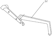
Fig. 2 is the structural representation with bi-directional configuration fire grate segment of backstepping and forwards function of the present invention;
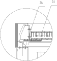
Fig. 3 is the local structure for amplifying schematic diagram of mechanical compensating mechanism of the present invention.
The specific embodiment
By describing the technology of the present invention content, structural feature in detail, being realized purpose and effect, below in conjunction with embodiment and cooperate accompanying drawing to know clearly to give explanation.
Now in conjunction with Fig. 1-3 preferred embodiment that a kind of two sections inverse-push of the present invention add the reciprocating fire grate stove of one section pusher type fire grate is described in further detail: a kind of two sections inverse-push add the reciprocating fire grate stove of one section pusher type fire grate, comprise feed system 1, fire grate 2, put grey passage 3, electrohydraulic control system 4, deslagging device 5, fire grate automatic control system 6, and air compartment 7, fire grate 2 is divided into from high to low successively: dryer section 21, burning zone 22 and burning segment 23, there is height fall between every section, dryer section 21 and burning zone 22 are inverse-push fire grate 24, and burning segment is pusher type fire grate 25.
Now be described in detail respectively as follows with regard to critical piece:
1, feed system 1
Described feed system 1 comprises charging conduit 11, baffle door 12, water-cooled skewed slot 13, and the garbage pusher device 14 that is positioned at fire grate 2 the place aheads.Charging conduit 11 is that the rubbish that grab bucket drops into is temporarily stored, and sends into the incinerator internal combustion again.Charging conduit 11 is comprised of upper front wall, top rear wall, charging conduit upper portion side wall, pars intermedia and water leg, each parts all adopt bolt-connection and in interior welds to reach sealing.Charging conduit 11 pars intermedias are equipped with the baffle door 12 of hydraulic pressure, need close when the incinerator start and stop and under the state of emergency.Charging conduit 11 adopts water-cooling pattern, can avoid the rubbish spontaneous combustion by heating.Charging conduit 11 top rear walls are equipped with anti-block apparatus, are used for abolishing rubbish bridging phenomenon.
2, fire grate 2
Inverse-push fire grate 21
The inverse-push fire grate 24 of described dryer section 21 and burning zone 22 is single-row design, and all independently adopt a hydraulic oil cylinder driving in the electrohydraulic control system 4, the bed surface of inverse-push fire grate 24 is 25 ° and is in tilted layout, fixed grate film and movable furnace grate plate dispose with interlace mode, the range of the movable furnace grate plate of inverse-push fire grate 24 is 250mm, and the top of the fire grate segment of inverse-push fire grate 24 is provided with exhaust vent, and fire grate segment connects with bolt at horizontal direction, one end is fixed, and integral body expands to opposite side; The left side of described fire grate is provided with mechanical compensating mechanism 26(as shown in Figure 3), this mechanical compensating mechanism 26 is positioned at the burner hearth left side, consistent with other grate furnace common structures, mainly be to play the effect of expanding with heat and contract with cold, the assurance fire grate segment is close to the side brake pad all the time under heating status, stop improper air leakage phenomena; The inverse-push fire grate 24 of described dryer section 21 and burning zone 22 arranges respectively and puts grey passage 3, is in particular two collection buckets are set, and the fine particle that is dropped by inverse-push fire grate gap can be collected into deslagging device; Whole fire grate framework mainly is comprised of bottom fixed frame, side fixed frame and side compensation framework etc., is installed on the brace summer of incinerator.Fire grate segment adopts heat resisting cast steel to make, and described inverse-push fire grate 24 comprises furnace grate support, fire grate assembly, stop, transmission framework, roller devices, pull rod device, middle transition section, fixing seal case, air compartment segmenting device, guide wheel device and side compensation arrangement.
The fire grate segment of the bi-directional configuration with backstepping and forwards function is adopted in the last grate furnace screening 241 of the inverse-push fire grate 24 of described burning zone, when operation, the upper left side motion is done in end grate furnace screening 241 under the hydraulic cylinder effect of electrohydraulic control system 4, burner hearth rubbish is backstepping, when hydraulic cylinder sets back, this special fire grate segment is done the lower right motion, and burner hearth rubbish is forwards.The fire grate segment of bi-directional configuration is as batch layer adjusting device, is used for adjusting rubbish at the floor height of burning zone, prevents that rubbish from piling up in the backstepping section; The rubbish of burning zone is fallen into through one section height fall on the bed surface of pusher type fire grate and is continued to burn, thereby make putrid organic matter become inorganic matter because of burning, pathogenic organism is because eliminating under high temperature incineration, the not flammable composition of generation and burn after ash fall into deslagging device and release outside the stove;
Inverse-push fire grate 24 has the following advantages:
1. scorching hot material mixes the rubbish of new adding and scorching hot layer along the stoker surface upward sliding, and therefore dry and igniting can be finished within very short time.
2. in combustion process, whole waste layer can be reached completing combustion like this by uniform stirring.Residual combustible is by same burning away against sending mode to send the combustion zone back to, and can making so not, burnout rate is controlled in the very little scope.
3. drying and combustion process are carried out at the backstepping fire grate respectively, can control the action of fire grate respectively according to the characteristic of rubbish, when msw water content larger, when calorific value is low, can come proper extension dryer section length by physical length or the control hydraulic cylinder fltting speed that prolongs the dryer section fire grate, to reach the purpose that prolongs the rubbish time of staying, guarantee that rubbish has enough dry places and the sufficient time of staying and completing combustion.
4. fully stirred owing to waste layer, so the bed of material is very smooth, fired state is stable, and the fluctuation of fire box temperature can be controlled in the very little scope.
5. dryer section and burning zone fire grate bottom are respectively equipped with independent air compartment, and the electric operator of arranging according to the outside carries out the independent adjusting of air quantity, make the air of burning distribute easier layout and adjusting.
6. can according to combustion position, by the bi-directional configuration of end, fire grate second segment backstepping section grate furnace screening, control bed depth.
Pusher type fire grate 25
The pusher type fire grate 25 of described burning segment is located at the outlet below of the last grate furnace screening 241 of burning zone, the fire grate body is single-row design, adopt the independent hydraulic oil cylinder driving in the electrohydraulic control system 4, pusher type fire grate 25 is 12.5 ° and is in tilted layout, fixed grate film and movable furnace grate plate dispose with interlace mode, and the range of the moving grate of pusher type fire grate is 280mm; The bottom of the pusher type fire grate 25 of described burning segment 23 arranges a collection bucket, the fine particle that is dropped by forwards fire grate gap can be collected into the slag releasing channel 51 of deslagging device 5; Described pusher type fire grate 25 comprises forwards furnace grate support, stop gauge, side drive device, travel(l)ing rest, fire grate assembly, left side compensation arrangement, right side fixture, final stage fire grate bearing, roll wheel assembly and guide wheel assemblies.
Pusher type fire grate 25 has the following advantages:
1. be provided with step between backstepping fire grate and the forwards fire grate, namely height fall makes to burn with the cinder that does not burn and can stir further, makes it burning fully, has guaranteed the burn decrement rate of waste incineration.
2. by the single movement control to the forwards fire grate, guarantee that incinerator has higher overload capacity.
3. forwards fire grate bottom is provided with independent air compartment, can carry out according to electric operator the independent adjusting of air quantity, makes the air of burning distribute easier layout and adjusting.
3, air compartment 7 and put grey passage 3
Described air compartment 7 and put grey passage 3 and comprise be positioned at inverse-push fire grate 24 belows 4 independently backstepping air compartments 71 and be positioned at 1 of pusher type fire grate 25 belows independently forwards air compartment 72, and each backstepping air compartment 71 is equipped with fan-shaped air door 711, be positioned at 4 fan-shaped regulating device of air door 73 in backstepping air compartment 71 outsides, regulate separately to realize air quantity; Be positioned at and connect air compartment 7 and the pneumatic ash handling equipment 74 of putting grey passage 3, and be positioned at below each air compartment, the grey passage 3 of putting that connects backstepping blowing pipe and forwards blowing pipe, and dispose a high pressure deashing blower fan 75, be positioned at the top of putting grey passage, play the effect of regularly blowing ash, will be blown into by the fine particle that the fire grate gap falls into air compartment the slag releasing channel 51 of deslagging device 5.The equal linkage of all air doors also can be according to combustion case in the convenient aperture of adjusting air door of master-control room, to realize best combustion efficiency; Combustion zone on four groups of corresponding fire grate bodies of air doors difference in the air compartment of described dryer section and burning zone, every group of air door regulated by the electric operator that is arranged on the air compartment outside, the aperture of each air door can show and adjusting at fire grate PLC, according to incineration firing state in the stove, can regulate separately the air quantity of each combustion zone, obtain the best combustion effect.Each air door regulating mechanism is linkage, also can drive separately.
4, electrohydraulic control system 4
Described electrohydraulic control system 4 comprises the cylinder drive 41 of the inverse-push fire grate top that is separately positioned on dryer section, the cylinder drive 42 of the inverse-push fire grate below of burning zone, the cylinder drive 43 of pusher type fire grate, the cylinder drive 44 of feed system 1, the cylinder drive 45 of deslagging device 5 sides.The action of each of described fire grate section fire grate body drives by each executive component of described electrohydraulic control system 4.Described electrohydraulic control system 4 comprises Hydraulic Station, each hydraulic pressure components and parts, hydraulic valve bank and electrical equipment control annex.
5, deslagging device 5
Described deslagging device 5 is positioned at the below of the fire grate segment end of pusher type fire grate 25, comprises particularly slag releasing channel 51, middle type metal expansion joint 52, the hydraulic cleanout machine 53 of passage.
6, the fire grate automatic control system 6
Described fire grate automatic control system 6 is take the PLC(programmable logic controller (PLC)) be core component, adopted boiler capacity (or furnace temperature) to stablize control principle, to guarantee incinerator, reliably operation stable according to the Numerical Implementation of setting.The fire grate automatic control system 6 of incinerator, can show intuitively and regulate the running status of each parts of fire grate, and each operational factor of fire grate can be sent to central control room by communications protocol as user interface with color LCD screen.The operations staff can monitor and regulate the parameter of fire grate at Central Control Room.
7, other
Changeover portion: the height fall between every section is formed by the step that falls that forms the about 700mm of drop, and this falls step and specifically forms drop and be about 700mm, can make the rubbish of burning conglomeration fall broken further burning; Make to burn with the cinder that does not burn and to stir further, make it burning fully, guaranteed the burn decrement rate of waste incineration.
Form the grate furnace primary zone by dryer section 21, burning zone 22 and burning segment 23, be provided with grey backflow interface 10 in the top of this primary zone's burning segment 23, this grey backflow interface 10 that falls is communicated with 23 with the burning segment of primary zone, the flue dust that is used for the secondary combustion chamber (not shown) of collection burning facility, large flue dust in the flue gas of secondary combustion chamber capture returned the primary zone by ash tube further burn, circulation in forming.
The length of the inverse-push fire grate 24 of described dryer section 21 can be regulated, particularly, adjusting refers to prolong the length of inverse-push fire grate 24, increase fire grate segment, can carry out according to the characteristic of rubbish the adjusting of fire grate length, when msw water content larger, when calorific value is low, but proper extension dryer section length guarantees that rubbish has enough dry places and the sufficient time of staying and completing combustion.
Operation principle of the present invention and processing procedure are as follows: rubbish promotes and sends into the charging conduit 11 that is positioned at the incinerator top through grab bucket, instruction according to burning control, use fluid pressure type pulling glassware 14 rubbish to be pushed on the inverse-push fire grate 24 of the dryer section 21 that tilts in the burner hearth by the speed of setting, by the operation of fire grate rubbish is constantly stirred and pushes it against and advance, finish drying, catch fire, the process of burning, on the batch layer adjusting device of inverse-push fire grate 24 ends of burning zone 22, continue to burn through poor pusher type fire grate 25 bed surfaces of falling into of a paragraph subsequently, thereby make putrid organic matter become inorganic matter because of burning, pathogenic organism is because eliminating under high temperature incineration, the not flammable composition of generation and burn after ash fall into deslagging device 5 and release outside the stove.A whole set of incinerator adopts hydraulic-driven, and the action of all fire grate parts is finished by each executive component of electrohydraulic control system 4.The fire grate automatic control system 6 of this incinerator is take PLC as core component, has adopted boiler capacity (or furnace temperature) to stablize control principle, to guarantee incinerator, reliably operation stable according to the Numerical Implementation of setting.
The above only is embodiments of the invention; be not so limit claim of the present invention; every equivalent structure or equivalent flow process conversion that utilizes specification of the present invention and accompanying drawing content to do; or directly or indirectly be used in other relevant technical fields, all in like manner be included in the scope of patent protection of the present invention.
Claims (10)
1. two sections inverse-push add the reciprocating fire grate stove of one section pusher type fire grate, comprise feed system, fire grate and deslagging device, it is characterized in that: described fire grate is divided into from high to low successively: dryer section, burning zone and burning segment, there is height fall between every section, the fire grate body of dryer section and burning zone is inverse-push, and the fire grate body of burning segment is pusher type.
2. two sections inverse-push according to claim 1 add the reciprocating fire grate stove of one section pusher type fire grate, it is characterized in that: described reciprocating fire grate stove also comprises electrohydraulic control system, described electrohydraulic control system comprises the cylinder drive of the inverse-push fire grate top that is separately positioned on dryer section, the cylinder drive of the inverse-push fire grate below of burning zone, the cylinder drive of the pusher type fire grate of burning segment, the cylinder drive of feed system, the cylinder drive of deslagging device side.
3. two sections inverse-push according to claim 2 add the reciprocating fire grate stove of one section pusher type fire grate, it is characterized in that: the fire grate segment of the bi-directional configuration with backstepping and forwards function that is driven by electrohydraulic control system is adopted in the last grate furnace screening of the inverse-push fire grate of described burning zone, and the flexible correspondence of electrohydraulic control system acts on backstepping and the forwards of fire grate segment.
4. two sections inverse-push of work according to claim 1 add the reciprocating fire grate stove of one section pusher type fire grate, it is characterized in that: form the grate furnace primary zone by dryer section, burning zone and burning segment, be provided with grey backflow interface in the top of this primary zone's burning segment, this grey backflow interface that falls is communicated with the burning segment of primary zone.
5. two sections inverse-push according to claim 1 add the reciprocating fire grate stove of one section pusher type fire grate, it is characterized in that: the height fall between every section of described dryer section, burning zone and the burning segment is formed by the step that falls that forms drop.
6. two sections inverse-push according to claim 1 add the reciprocating fire grate stove of one section pusher type fire grate, it is characterized in that: the inverse-push fire grate of described dryer section and burning zone is single-row design, and all adopt a hydraulic oil cylinder driving, the bed surface of inverse-push fire grate is 25 ° and is in tilted layout and is disposed with interlace mode by fixed grate film and movable furnace grate plate, the range of the movable furnace grate plate of inverse-push fire grate is 250mm, the top of the fire grate segment of inverse-push fire grate is provided with exhaust vent, this fire grate segment connects with bolt at horizontal direction, one end is fixed, and integral body expands to opposite side.
7. two sections inverse-push according to claim 1 add the reciprocating fire grate stove of one section pusher type fire grate, it is characterized in that: the left side of described fire grate is provided with and prevents the mechanical compensating mechanism that can expand with heat and contract with cold that leaks out.
8. two sections inverse-push of work according to claim 1 add the reciprocating fire grate stove of one section pusher type fire grate, it is characterized in that: the pusher type fire grate of described burning segment is located at the outlet below of terminal fire grate segment of the inverse-push fire grate of burning zone, the fire grate body is single-row design, adopt a hydraulic oil cylinder driving, pusher type fire grate is 12.5 ° and is in tilted layout and is disposed with interlace mode by fixed grate film and movable furnace grate plate, and the range of the moving grate of pusher type fire grate is 280mm.
9. two sections inverse-push according to claim 1 add the reciprocating fire grate stove of one section pusher type fire grate, it is characterized in that: described reciprocating fire grate stove also comprises fire grate automatic control system, air compartment and puts grey passage.
10. two sections inverse-push according to claim 9 add the reciprocating fire grate stove of one section pusher type fire grate, it is characterized in that: described air compartment comprises be positioned at backstepping fire grate body below 4 independently backstepping air compartments and be positioned at 1 of forwards fire grate body below independently forwards air compartment, and each backstepping air compartment is equipped with fan-shaped air door, is positioned at 4 fan-shaped regulating device of air door in the backstepping air compartment outside.
Priority Applications (1)
| Application Number | Priority Date | Filing Date | Title |
|---|---|---|---|
| CN201210440169XA CN102901108A (en) | 2012-11-07 | 2012-11-07 | Reciprocating grate furnace with two-section-reverse-acting and one-section-forward-acting grate |
Applications Claiming Priority (1)
| Application Number | Priority Date | Filing Date | Title |
|---|---|---|---|
| CN201210440169XA CN102901108A (en) | 2012-11-07 | 2012-11-07 | Reciprocating grate furnace with two-section-reverse-acting and one-section-forward-acting grate |
Publications (1)
| Publication Number | Publication Date |
|---|---|
| CN102901108A true CN102901108A (en) | 2013-01-30 |
Family
ID=47573494
Family Applications (1)
| Application Number | Title | Priority Date | Filing Date |
|---|---|---|---|
| CN201210440169XA Pending CN102901108A (en) | 2012-11-07 | 2012-11-07 | Reciprocating grate furnace with two-section-reverse-acting and one-section-forward-acting grate |
Country Status (1)
| Country | Link |
|---|---|
| CN (1) | CN102901108A (en) |
Cited By (9)
| Publication number | Priority date | Publication date | Assignee | Title |
|---|---|---|---|---|
| CN103742922A (en) * | 2014-01-15 | 2014-04-23 | 重庆科技学院 | Clockwise and anticlockwise push comprehensive system for grates |
| CN103742923A (en) * | 2014-01-15 | 2014-04-23 | 重庆科技学院 | Clockwise and anticlockwise push comprehensive guide rail device for grates |
| CN104534479A (en) * | 2014-12-31 | 2015-04-22 | 杭州新世纪能源环保工程股份有限公司 | Reciprocating-type three-section driving garbage incinerator suitable for total life cycle garbage |
| CN104595907A (en) * | 2015-02-02 | 2015-05-06 | 安徽盛燃焚烧炉科技有限公司 | Fixed grate and incineration system applying same |
| CN109405276A (en) * | 2018-09-30 | 2019-03-01 | 农业部规划设计研究院 | A kind of straw bundle burning boiler cleaning heating system |
| CN109519926A (en) * | 2018-12-04 | 2019-03-26 | 杭州新世纪能源环保工程股份有限公司 | A kind of maintenance observation channel of two sections of reciprocating waste incinerators |
| CN110953593A (en) * | 2019-12-13 | 2020-04-03 | 杭州新世纪能源环保工程股份有限公司 | General industrial waste incinerator with variable reverse-pushing grate angle |
| CN116293693A (en) * | 2023-02-15 | 2023-06-23 | 江苏耀先环境设备有限公司 | Grate type incinerator and preparation method thereof |
| CN116293693B (en) * | 2023-02-15 | 2024-04-12 | 江苏耀先环境设备有限公司 | Grate type incinerator and preparation method thereof |
Citations (4)
| Publication number | Priority date | Publication date | Assignee | Title |
|---|---|---|---|---|
| CN1162646C (en) * | 2002-04-23 | 2004-08-18 | 屠柏锐 | Domestic refuse incinerator |
| KR100861030B1 (en) * | 2008-03-10 | 2008-09-30 | 지이큐솔루션 주식회사 | Combustion grate having horizontal arrangement |
| CN100507364C (en) * | 2007-08-01 | 2009-07-01 | 重庆科技学院 | Sectional drive combined type fire grate system |
| CN202993221U (en) * | 2012-11-07 | 2013-06-12 | 福建省丰泉环保控股有限公司 | Reciprocating grate furnace with grate including two reverse pushing-type sections and one forward pushing-type section |
-
2012
- 2012-11-07 CN CN201210440169XA patent/CN102901108A/en active Pending
Patent Citations (4)
| Publication number | Priority date | Publication date | Assignee | Title |
|---|---|---|---|---|
| CN1162646C (en) * | 2002-04-23 | 2004-08-18 | 屠柏锐 | Domestic refuse incinerator |
| CN100507364C (en) * | 2007-08-01 | 2009-07-01 | 重庆科技学院 | Sectional drive combined type fire grate system |
| KR100861030B1 (en) * | 2008-03-10 | 2008-09-30 | 지이큐솔루션 주식회사 | Combustion grate having horizontal arrangement |
| CN202993221U (en) * | 2012-11-07 | 2013-06-12 | 福建省丰泉环保控股有限公司 | Reciprocating grate furnace with grate including two reverse pushing-type sections and one forward pushing-type section |
Cited By (11)
| Publication number | Priority date | Publication date | Assignee | Title |
|---|---|---|---|---|
| CN103742922A (en) * | 2014-01-15 | 2014-04-23 | 重庆科技学院 | Clockwise and anticlockwise push comprehensive system for grates |
| CN103742923A (en) * | 2014-01-15 | 2014-04-23 | 重庆科技学院 | Clockwise and anticlockwise push comprehensive guide rail device for grates |
| CN103742922B (en) * | 2014-01-15 | 2016-03-02 | 重庆科技学院 | Along backstepping fire grate integrated system |
| CN103742923B (en) * | 2014-01-15 | 2016-08-17 | 重庆科技学院 | Along the comprehensive track-type facilities of backstepping fire grate |
| CN104534479A (en) * | 2014-12-31 | 2015-04-22 | 杭州新世纪能源环保工程股份有限公司 | Reciprocating-type three-section driving garbage incinerator suitable for total life cycle garbage |
| CN104595907A (en) * | 2015-02-02 | 2015-05-06 | 安徽盛燃焚烧炉科技有限公司 | Fixed grate and incineration system applying same |
| CN109405276A (en) * | 2018-09-30 | 2019-03-01 | 农业部规划设计研究院 | A kind of straw bundle burning boiler cleaning heating system |
| CN109519926A (en) * | 2018-12-04 | 2019-03-26 | 杭州新世纪能源环保工程股份有限公司 | A kind of maintenance observation channel of two sections of reciprocating waste incinerators |
| CN110953593A (en) * | 2019-12-13 | 2020-04-03 | 杭州新世纪能源环保工程股份有限公司 | General industrial waste incinerator with variable reverse-pushing grate angle |
| CN116293693A (en) * | 2023-02-15 | 2023-06-23 | 江苏耀先环境设备有限公司 | Grate type incinerator and preparation method thereof |
| CN116293693B (en) * | 2023-02-15 | 2024-04-12 | 江苏耀先环境设备有限公司 | Grate type incinerator and preparation method thereof |
Similar Documents
| Publication | Publication Date | Title |
|---|---|---|
| CN102901108A (en) | Reciprocating grate furnace with two-section-reverse-acting and one-section-forward-acting grate | |
| CN202993221U (en) | Reciprocating grate furnace with grate including two reverse pushing-type sections and one forward pushing-type section | |
| CN203744266U (en) | Auxiliary thermal power generation system for waste incineration | |
| CN102607037B (en) | Multistage hydraulic mechanical garbage incinerator and control method for same | |
| CN102878563B (en) | Multi-drive high-pressure-loss fire grate type household garbage burning device | |
| CN101852438A (en) | Waste incineration boiler | |
| CN108105757A (en) | A kind of novel anti-coking intelligent and high-efficiency type biomass heating furnace | |
| CN106224974A (en) | Waste incineration processing system | |
| CN102607036B (en) | Multistage hydraulic mechanical garbage incinerator | |
| CN106500111A (en) | Refuse burning system | |
| CN2937842Y (en) | Combined garbage burner | |
| CN208442834U (en) | Reciprocating fire grate furnace for domestic garbage burning electricity generation | |
| CN206430163U (en) | A kind of refuse burning system | |
| CN107726367A (en) | A kind of biomass granule fuel heating-cooking dual-purpose stove | |
| CN102913916B (en) | Moving grate drying bed-circulating fluidized bed boiler-compounded incineration equipment | |
| CN2568977Y (en) | Refuse incinerator with stepped horizontal reciprocating fire grate | |
| CN102519043A (en) | Mechanical grate of large-sized incinerator | |
| CN113587100A (en) | Household garbage incineration grate system | |
| CN102927572B (en) | Garbage burning equipment with forward-pushing three-section type cooling high-pressure loss fire grate and method for burning garbage by using garbage burning equipment | |
| CN102734806B (en) | Water-cooled reciprocating-type multi-stage hydraulic mechanical grate furnace and control method thereof | |
| CN105003910A (en) | Centralized heat supply device adopting biomass briquette as raw materials | |
| CN105042604A (en) | Automatic decoking combustion chamber for combusting biomass fuel | |
| CN217423261U (en) | Novel environment-friendly garbage incinerator | |
| KR102238864B1 (en) | A garbage incineration system | |
| CN100549521C (en) | Vertical life refuse heat decomposition incinerator |
Legal Events
| Date | Code | Title | Description |
|---|---|---|---|
| C06 | Publication | ||
| PB01 | Publication | ||
| C10 | Entry into substantive examination | ||
| SE01 | Entry into force of request for substantive examination | ||
| C02 | Deemed withdrawal of patent application after publication (patent law 2001) | ||
| WD01 | Invention patent application deemed withdrawn after publication |
Application publication date: 20130130 |