CN102882408A - Power unit of inverter - Google Patents
Power unit of inverter Download PDFInfo
- Publication number
- CN102882408A CN102882408A CN2012104239099A CN201210423909A CN102882408A CN 102882408 A CN102882408 A CN 102882408A CN 2012104239099 A CN2012104239099 A CN 2012104239099A CN 201210423909 A CN201210423909 A CN 201210423909A CN 102882408 A CN102882408 A CN 102882408A
- Authority
- CN
- China
- Prior art keywords
- radiator
- power
- circuit
- output
- base plate
- Prior art date
- Legal status (The legal status is an assumption and is not a legal conclusion. Google has not performed a legal analysis and makes no representation as to the accuracy of the status listed.)
- Pending
Links
- 239000003990 capacitor Substances 0.000 claims abstract description 23
- 230000001681 protective effect Effects 0.000 claims abstract description 18
- 239000010409 thin film Substances 0.000 claims abstract description 15
- RYGMFSIKBFXOCR-UHFFFAOYSA-N Copper Chemical compound [Cu] RYGMFSIKBFXOCR-UHFFFAOYSA-N 0.000 claims abstract description 8
- 239000010949 copper Substances 0.000 claims abstract description 8
- 229910052802 copper Inorganic materials 0.000 claims abstract description 7
- 230000003321 amplification Effects 0.000 claims description 9
- 238000003199 nucleic acid amplification method Methods 0.000 claims description 9
- 238000012545 processing Methods 0.000 claims description 9
- 239000000758 substrate Substances 0.000 abstract description 8
- 238000009434 installation Methods 0.000 abstract description 2
- 229910000881 Cu alloy Inorganic materials 0.000 description 2
- 238000007664 blowing Methods 0.000 description 2
- 238000010586 diagram Methods 0.000 description 2
- 230000000694 effects Effects 0.000 description 2
- 238000005516 engineering process Methods 0.000 description 2
- 238000012423 maintenance Methods 0.000 description 2
- 230000005855 radiation Effects 0.000 description 2
- 238000005070 sampling Methods 0.000 description 2
- 229910000838 Al alloy Inorganic materials 0.000 description 1
- 239000000956 alloy Substances 0.000 description 1
- 239000004411 aluminium Substances 0.000 description 1
- XAGFODPZIPBFFR-UHFFFAOYSA-N aluminium Chemical compound [Al] XAGFODPZIPBFFR-UHFFFAOYSA-N 0.000 description 1
- 229910052782 aluminium Inorganic materials 0.000 description 1
- 230000009286 beneficial effect Effects 0.000 description 1
- 238000006243 chemical reaction Methods 0.000 description 1
- 150000001875 compounds Chemical class 0.000 description 1
- 230000007812 deficiency Effects 0.000 description 1
- 238000001514 detection method Methods 0.000 description 1
- 238000011161 development Methods 0.000 description 1
- 238000009413 insulation Methods 0.000 description 1
- 230000010354 integration Effects 0.000 description 1
- 238000000034 method Methods 0.000 description 1
- 239000000203 mixture Substances 0.000 description 1
- 239000003381 stabilizer Substances 0.000 description 1
Images


Classifications
-
- Y—GENERAL TAGGING OF NEW TECHNOLOGICAL DEVELOPMENTS; GENERAL TAGGING OF CROSS-SECTIONAL TECHNOLOGIES SPANNING OVER SEVERAL SECTIONS OF THE IPC; TECHNICAL SUBJECTS COVERED BY FORMER USPC CROSS-REFERENCE ART COLLECTIONS [XRACs] AND DIGESTS
- Y02—TECHNOLOGIES OR APPLICATIONS FOR MITIGATION OR ADAPTATION AGAINST CLIMATE CHANGE
- Y02E—REDUCTION OF GREENHOUSE GAS [GHG] EMISSIONS, RELATED TO ENERGY GENERATION, TRANSMISSION OR DISTRIBUTION
- Y02E10/00—Energy generation through renewable energy sources
- Y02E10/50—Photovoltaic [PV] energy
- Y02E10/56—Power conversion systems, e.g. maximum power point trackers
Landscapes
- Inverter Devices (AREA)
Abstract
The invention discloses a power unit of an inverter for high-power photovoltaic on-grid power stations. A thin-film capacitor is arranged on the left side of a position above a baseplate, and the top of the thin-film capacitor is connected with the input end of a power module through a laminated bus; a radiator is arranged on the right side of a position above the baseplate, the power module is arranged on the upper surface of the radiator, a drive circuit and a protective circuit thereof are closely adhered to the upside of the power module, a current sensor is fixedly connected above the power module and close to the output end of the power module, and the output end of the power module is fixedly connected with an AC copper bar passing through the center of the current sensor; and the rear side of the radiator is provided with a fan fixedly connected with a substrate of the radiator. Through the reasonable layout of the power unit in space, the installation area of the whole power unit is close to the area of the substrate of the radiator, and the structure of the power unit is compact, therefore, the power unit is a highly integrated power device, and can reduce the cost, save space, and meet the requirements of miniaturization.
Description
Technical field
The present invention relates to a kind of DC-to-AC converter, specifically be used for the power cell of the DC-to-AC converter in high-power photovoltaic synchronization power station.
Background technology
Along with the development of photovoltaic industry, be used for the be incorporated into the power networks high-power photovoltaic inverter in power station of large-scale photovoltaic and develop to low cost, high power density, miniaturization.The structure of the power cell in traditional high-power photovoltaic synchronization DC-to-AC converter is consulted Fig. 1, comprise that blower fan 1-1, radiator 1-2, electrochemical capacitor 1-3(16 are only), stack bus bar 1-4,4 current sensor 1-5, drive circuit 1-6,4 power model 1-7, wherein, radiator 1-2 is comprised of substrate and tooth bar, electrochemical capacitor 1-3 quantity is more, by the input of stack bus bar 1-4 with the both positive and negative polarity access power module 1-7 of electrochemical capacitor 1-3,4 power model 1-7 are installed on the substrate of radiator 1-2 together with parallel way.The output of each power model 1-7 is equipped with corresponding current sensor 1-5, and 4 power model 1-7 and 4 current sensor 1-5 are arranged in above the front of radiator 1-2; Drive circuit 1-6 is positioned at the positive top of power model 1-7; A plurality of electrochemical capacitor 1-3 are positioned at a side on the long limit of radiator 1-2, blower fan 1-1 is installed in radiator 1-2 minor face one side, and blower fan 1-1 is fixed on the substrate, the air outlet of blower fan 1-1 is aimed at the tooth bar blowing of radiator 1-2, that is to say that electrochemical capacitor 1-3 and blower fan 1-1 are arranged at respectively on the adjacent two sides of radiator 1-2.Following some weak point of above-mentioned traditional power cell ubiquity:
1, power conversion adopts many power models 1-7 parallel way, and there is the uneven flow problem of sound attitude in many power models 1-7 parallel connection, causes easily power model 1-7 to burn when operation.
2, under higher switching frequency, the loss of power model 1-7 is larger, is the balance heat radiation, needs to drop into larger area radiator 1-2, needs simultaneously the blower fan 1-1 than Wind Volume, has therefore increased the cost of inverter.
3, be raising system direct voltage grade, take a plurality of electrochemical capacitor 1-3 series-parallel systems, so that stack bus bar 1-4 complex structural designs, distributed inductance is larger; And electrochemical capacitor 1-3 is shorter useful life, changes often, and maintenance cost is high.
4, be positioned at the power model 1-7 at blower fan 1-1 air inlet place owing to close on fan, temperature is lower, and is positioned at the power model 1-7 of blower fan 1-1 air outlet because away from blower fan, temperature is higher, therefore, there is the heat history effect in air channel, can affects utilization rate and the reliability of power model 1-7.
Summary of the invention
The objective of the invention is for the deficiency that overcomes above-mentioned conventional power unit provide a kind of reliable, cost is low, long service life, inverter power unit that efficient is high.
For achieving the above object, the technical solution used in the present invention is: the present invention includes blower fan, radiator, stack bus bar, current sensor, power model, base plate, base plate is positioned at the bottom, the left side, top of base plate is provided with thin-film capacitor, and the top of thin-film capacitor connects the input of a power model by stack bus bar; The right side, top of base plate is provided with radiator, be fixedly installed described power model on the upper surface of radiator, the top of described power model is glued with drive circuit and protective circuit thereof, above described power model and near its output, be fixedly connected with a current sensor, the affixed AC copper bar that passes the current sensor center of the output of described power model; The rear side of radiator arranges a blower fan that is fixedly connected with radiator base plate.
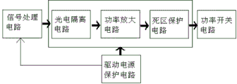
Described drive circuit and protective circuit thereof comprise signal processing circuit, photoelectric isolating circuit, power amplification circuit, dead zone protecting circuit, power switch circuit, driving power protective circuit, the input of photoelectric isolating circuit connects the signal processing circuit output, the output of photoelectric isolating circuit connects the input of power amplification circuit, the output of power amplification circuit connects the input of dead zone protecting circuit, and the output of dead zone protecting circuit connects the input of power switch circuit; When driving power is normal, Drive Protecting Circuit output high level signal, when driving power is lower than 15V, Drive Protecting Circuit output low level signal, signal processing circuit is turn-offed and is driven signal.
Further, radiator is comprised of radiator base plate and a plurality of radiator tooth bar, be rectangular shape, the long edge fore-and-aft direction of cuboid, minor face is along left and right directions, the lower surface of described radiator base plate is all arranged and all vertically be fixedly connected with to each described radiator tooth bar along the long side direction of cuboid, the air outlet of described blower fan faces described radiator tooth bar.
After the present invention adopts technique scheme, compare with the conventional inverter power cell, have following beneficial effect:
1, the present invention passes through at space reasonable Arrangement thin-film capacitor, stack bus bar, power model, drive circuit, current sensor, radiator and blower fan, make the area of substrate of the erection space of whole inverter power unit and radiator close, volume is less, structure is more compact, each several part is integrated, be the power device of Highgrade integration, reduce the cost of power cell, the space of saving power unit, thus can satisfy the demand of miniaturization.
2, the air outlet of blower fan acts on the most of zone of tooth bar of radiator among the present invention, and it is more even to dispel the heat, and can improve utilization rate and the reliability of power model.
3, the present invention only uses an independent power model and single current sensor, can reduce the area of radiator, and erection space is less than the conventional power unit, saves cost, the maintenance of convenient blower fan.
4, the drive circuit among the present invention and protective circuit thereof can increase its life cycle so that whole power cell is safer reliable, strengthen the reliability of system.
5, to adopt thin-film capacitor and power model be the compound mode of core in the present invention, the advantage that thin-film capacitor has is nonpolarity, dielectric loss is few, insulation impedance is high, the life-span is long, replace traditional electrochemical capacitor so that power cell has better effect with thin-film capacitor, solved the problems such as the ubiquitous efficient of power cell is not high in the high-power inverter, useful life short, integrated level is not high.
Description of drawings
In order to be easy to explanation, the present invention is described in detail by following the drawings and the specific embodiments.
Fig. 1 is inverter power unit package assembly schematic diagram traditional in the background technology;
Fig. 2 is inverter power unit package assembly schematic perspective view of the present invention;
Fig. 3 is the exploded view of Fig. 2;
Fig. 4 is the composition diagram of drive circuit and protective circuit thereof among Fig. 2;
1. blower fan; 2. radiator; The 2-1 radiator base plate; 2-2 radiator tooth bar; 3. thin-film capacitor; 4. stack bus bar; 5. current sensor; 6. drive circuit and protective circuit thereof; 7. power model; 8.AC copper bar; 9. the left fixed head of radiator; 10. the right fixed head of radiator; 11. electric capacity fixed head; 12. base plate.
Embodiment
Shown in Fig. 2-3, inverter power unit of the present invention comprises blower fan 1, radiator 2, a plurality of thin-film capacitor 3, stack bus bar 4, current sensor 5, drive circuit and protective circuit 6 thereof, power model 7, AC copper bar 8, base plate 12 etc.
Fix a power model 7 at the upper surface of radiator 2, power model 7 rated power are rated power sums of traditional 4 power models, the uneven flow problem of sound attitude when so not only avoiding high power module in parallel, the inconsistent problem of the temperature when also avoiding multiple module paralleling.
Be close to drive circuit and protective circuit 6 thereof above power model 7, be fixedly connected with a current sensor 5 above power model 7, current sensor 5 is near the output of power model 7.The output of power model 7 is AC copper bar 8 fixedly, and AC copper bar 8 passes the center of current sensor 5 simultaneously.Come the size of the output end current of detection power module 7 with single current sensor 5, the sampling error when having avoided so a plurality of transducers in parallel has improved the precision of sampling.
Rear side at radiator 2 is installed a blower fan 1, and blower fan 1 is screwed in radiator base plate 2-1 upper [U1], and the air outlet of blower fan 1 is conducive to heat radiation evenly like this over against radiator tooth bar 2-2 blowing.The quantity of blower fan 1 only is 1, and air quantity does not need too large.
As shown in Figure 4, drive circuit of the present invention and protective circuit 6 thereof mainly comprise signal processing circuit, photoelectric isolating circuit, power amplification circuit, dead zone protecting circuit, power switch circuit, driving power protective circuit.The input of photoelectric isolating circuit is connected on the corresponding output end of signal processing circuit; the output of photoelectric isolating circuit is connected to the input of power amplification circuit; the output of power amplification circuit is connected to the input of dead zone protecting circuit; the output of dead zone protecting circuit is connected to the input of power switch circuit, and the driving power protective circuit is then protected the power supply of drive circuit.Wherein, the driving power protective circuit mainly is comprised of resistance, voltage-stabiliser tube, triode and optocoupler.When driving power was normal, the protective circuit output signal was high level, and pull-up resistor can be got rid of the interference of outer bound pair output signal; in case driving power is lower than 15V, the optocoupler conducting, the protective circuit output signal is low level; signal processing circuit is turn-offed the driving signal immediately, and the output fault-signal.
Is which side problem: a side of shorter substrate actually? be which parts write by reference to the accompanying drawings, a side that is positioned at?
Now 3-1 illustrates by reference to the accompanying drawings, has indicated in the drawings orientation all around.
Claims (3)
1. inverter power unit, comprise blower fan (1), radiator (2), stack bus bar (4), current sensor (5), power model (7), base plate (12), base plate (12) is positioned at the bottom, it is characterized in that: the left side, top of base plate (12) is provided with thin-film capacitor (3), and the top of thin-film capacitor (3) connects the input of a power model (7) by stack bus bar (4); The right side, top of base plate (12) is provided with radiator (2), be fixedly installed described power model (7) on the upper surface of radiator (2), the top of described power model (7) is glued with drive circuit and protective circuit (6) thereof, be fixedly connected with a current sensor (5) in the top of described power model (7) and near its output, the affixed AC copper bar (8) that passes current sensor (5) center of the output of described power model (7); The rear side of radiator (2) arranges a blower fan (1) that is fixedly connected with radiator (2).
2. a kind of inverter power unit according to claim 1, it is characterized in that: described drive circuit and protective circuit thereof (6) comprise signal processing circuit, photoelectric isolating circuit, power amplification circuit, dead zone protecting circuit, power switch circuit, the driving power protective circuit, the input of photoelectric isolating circuit connects the signal processing circuit output, the output of photoelectric isolating circuit connects the input of power amplification circuit, the output of power amplification circuit connects the input of dead zone protecting circuit, and the output of dead zone protecting circuit connects the input of power switch circuit; When driving power is normal, Drive Protecting Circuit output high level signal, when driving power is lower than 15V, Drive Protecting Circuit output low level signal, signal processing circuit is turn-offed and is driven signal.
3. a kind of inverter power unit according to claim 1, it is characterized in that: radiator (2) is comprised of radiator base plate (2-1) and a plurality of radiator tooth bar (2-2), be rectangular shape, the long edge fore-and-aft direction of cuboid, minor face is along left and right directions, the lower surface of described radiator base plate (2-1) is all arranged and all vertically be fixedly connected with to each described radiator tooth bar (2-2) along the long side direction of cuboid, the air outlet of described blower fan (1) faces described radiator tooth bar (2-2).
Priority Applications (1)
| Application Number | Priority Date | Filing Date | Title |
|---|---|---|---|
| CN2012104239099A CN102882408A (en) | 2012-10-29 | 2012-10-29 | Power unit of inverter |
Applications Claiming Priority (1)
| Application Number | Priority Date | Filing Date | Title |
|---|---|---|---|
| CN2012104239099A CN102882408A (en) | 2012-10-29 | 2012-10-29 | Power unit of inverter |
Publications (1)
| Publication Number | Publication Date |
|---|---|
| CN102882408A true CN102882408A (en) | 2013-01-16 |
Family
ID=47483613
Family Applications (1)
| Application Number | Title | Priority Date | Filing Date |
|---|---|---|---|
| CN2012104239099A Pending CN102882408A (en) | 2012-10-29 | 2012-10-29 | Power unit of inverter |
Country Status (1)
| Country | Link |
|---|---|
| CN (1) | CN102882408A (en) |
Cited By (7)
| Publication number | Priority date | Publication date | Assignee | Title |
|---|---|---|---|---|
| CN103401434A (en) * | 2013-06-21 | 2013-11-20 | 国家电网公司 | Power unit of large-power current transformer |
| CN105098531A (en) * | 2015-09-23 | 2015-11-25 | 上海电科电器科技有限公司 | Connector of switch |
| CN110247611A (en) * | 2018-03-09 | 2019-09-17 | 上海电驱动股份有限公司 | A kind of integrated electrical device for high power controller |
| CN111245359A (en) * | 2020-01-20 | 2020-06-05 | 上海发电设备成套设计研究院有限责任公司 | Cascaded photovoltaic inverter unit module device and control method |
| CN111624923A (en) * | 2020-06-12 | 2020-09-04 | 绍宏机电(苏州)有限公司 | Low-voltage high-power controller structure |
| CN112005120A (en) * | 2018-04-24 | 2020-11-27 | 舍弗勒技术股份两合公司 | Hybrid drive train comprising two electric machines and an internal combustion engine |
| CN116232013A (en) * | 2023-05-06 | 2023-06-06 | 深圳市首航新能源股份有限公司 | Inverter and electrical equipment |
Citations (5)
| Publication number | Priority date | Publication date | Assignee | Title |
|---|---|---|---|---|
| CN1298568A (en) * | 1999-02-24 | 2001-06-06 | 三菱电机株式会社 | power driver |
| CN101188386A (en) * | 2007-11-26 | 2008-05-28 | 天津理工大学 | PWM rectification system based on DSP and CPLD |
| CN201789431U (en) * | 2010-08-04 | 2011-04-06 | 苏州西典机电有限公司 | General inverter module |
| CN201975982U (en) * | 2011-04-11 | 2011-09-14 | 浙江埃菲生能源科技有限公司 | IGBT (Insulated Gate Bipolar Translator) module of high-power converter |
| CN102522908A (en) * | 2011-12-09 | 2012-06-27 | 浙江永升新能源科技有限公司 | Modular structure of inverting units of photovoltaic grid-connected inverter |
-
2012
- 2012-10-29 CN CN2012104239099A patent/CN102882408A/en active Pending
Patent Citations (5)
| Publication number | Priority date | Publication date | Assignee | Title |
|---|---|---|---|---|
| CN1298568A (en) * | 1999-02-24 | 2001-06-06 | 三菱电机株式会社 | power driver |
| CN101188386A (en) * | 2007-11-26 | 2008-05-28 | 天津理工大学 | PWM rectification system based on DSP and CPLD |
| CN201789431U (en) * | 2010-08-04 | 2011-04-06 | 苏州西典机电有限公司 | General inverter module |
| CN201975982U (en) * | 2011-04-11 | 2011-09-14 | 浙江埃菲生能源科技有限公司 | IGBT (Insulated Gate Bipolar Translator) module of high-power converter |
| CN102522908A (en) * | 2011-12-09 | 2012-06-27 | 浙江永升新能源科技有限公司 | Modular structure of inverting units of photovoltaic grid-connected inverter |
Cited By (11)
| Publication number | Priority date | Publication date | Assignee | Title |
|---|---|---|---|---|
| CN103401434A (en) * | 2013-06-21 | 2013-11-20 | 国家电网公司 | Power unit of large-power current transformer |
| CN103401434B (en) * | 2013-06-21 | 2015-09-23 | 国家电网公司 | A kind of power unit of large-power current transformer |
| CN105098531A (en) * | 2015-09-23 | 2015-11-25 | 上海电科电器科技有限公司 | Connector of switch |
| CN110247611A (en) * | 2018-03-09 | 2019-09-17 | 上海电驱动股份有限公司 | A kind of integrated electrical device for high power controller |
| CN110247611B (en) * | 2018-03-09 | 2024-05-10 | 上海电驱动股份有限公司 | Integrated electrical device for high power controller |
| CN112005120A (en) * | 2018-04-24 | 2020-11-27 | 舍弗勒技术股份两合公司 | Hybrid drive train comprising two electric machines and an internal combustion engine |
| CN112005120B (en) * | 2018-04-24 | 2023-10-24 | 舍弗勒技术股份两合公司 | Hybrid drive train comprising two electric machines and an internal combustion engine |
| CN111245359A (en) * | 2020-01-20 | 2020-06-05 | 上海发电设备成套设计研究院有限责任公司 | Cascaded photovoltaic inverter unit module device and control method |
| CN111624923A (en) * | 2020-06-12 | 2020-09-04 | 绍宏机电(苏州)有限公司 | Low-voltage high-power controller structure |
| CN116232013A (en) * | 2023-05-06 | 2023-06-06 | 深圳市首航新能源股份有限公司 | Inverter and electrical equipment |
| CN116232013B (en) * | 2023-05-06 | 2023-08-04 | 深圳市首航新能源股份有限公司 | Inverter and electrical equipment |
Similar Documents
| Publication | Publication Date | Title |
|---|---|---|
| CN105957991B (en) | Battery module | |
| CN106058112A (en) | Cylindrical battery module | |
| CN105763076A (en) | Water-cooling type power unit | |
| CN209233705U (en) | A kind of high power high efficiency and heat radiation controller integrated control device | |
| CN203456525U (en) | Energy storage battery device | |
| CN204145263U (en) | Based on the water-cooled power cell of IGBT | |
| CN202454623U (en) | Unit thermal battery combination fixing frame | |
| CN204067381U (en) | Solar module | |
| CN208835986U (en) | A kind of power device of generic encapsulation | |
| CN203537004U (en) | Intelligent lithium battery stand-by power supply device | |
| CN106549584A (en) | Power modules for wind power converters | |
| CN102201727A (en) | Liquid cooling power module for electric vehicle | |
| CN204046403U (en) | Based on the wind cooling power unit of IGBT | |
| CN222015586U (en) | A square battery module | |
| CN204067393U (en) | Photovoltaic module convergent belt structure | |
| CN201478992U (en) | Detachable power unit water cooling system | |
| CN219892351U (en) | Battery module and battery | |
| CN102723878B (en) | High-power solar three-phase grid-connected inverter | |
| CN203617913U (en) | Off-grid inverter bus bar component | |
| CN204517672U (en) | A kind of power layout structure of independent capacitance module | |
| CN203193517U (en) | Inverter power module structure of insulated gate bipolar transistor (IGBT) | |
| CN207199734U (en) | Battery modules | |
| CN201616905U (en) | Solar environmental-protection active speaker | |
| CN205846059U (en) | A battery module | |
| CN214011457U (en) | Multi-channel power supply test system |
Legal Events
| Date | Code | Title | Description |
|---|---|---|---|
| C06 | Publication | ||
| PB01 | Publication | ||
| C10 | Entry into substantive examination | ||
| SE01 | Entry into force of request for substantive examination | ||
| C02 | Deemed withdrawal of patent application after publication (patent law 2001) | ||
| WD01 | Invention patent application deemed withdrawn after publication |
Application publication date: 20130116 |