CN102864596A - Reverse crank for industrial sewing machine - Google Patents
Reverse crank for industrial sewing machine Download PDFInfo
- Publication number
- CN102864596A CN102864596A CN2012103058363A CN201210305836A CN102864596A CN 102864596 A CN102864596 A CN 102864596A CN 2012103058363 A CN2012103058363 A CN 2012103058363A CN 201210305836 A CN201210305836 A CN 201210305836A CN 102864596 A CN102864596 A CN 102864596A
- Authority
- CN
- China
- Prior art keywords
- crank
- hole
- sewing machine
- boss
- industrial sewing
- Prior art date
- Legal status (The legal status is an assumption and is not a legal conclusion. Google has not performed a legal analysis and makes no representation as to the accuracy of the status listed.)
- Pending
Links
- 238000009958 sewing Methods 0.000 title claims abstract description 14
- 238000009434 installation Methods 0.000 abstract description 3
- 230000004048 modification Effects 0.000 description 2
- 238000012986 modification Methods 0.000 description 2
- 230000007812 deficiency Effects 0.000 description 1
- 238000000034 method Methods 0.000 description 1
Images
Landscapes
- Sewing Machines And Sewing (AREA)
Abstract
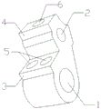
The invention relates to a reverse crank for an industrial sewing machine, and belongs to the field of machines. The reverse crank comprises a reverse crank body, wherein the reverse crank body comprises a first crank hole (1) and a second crank hole (2); a first boss (3) is arranged on the upper part of the first crank hole (1); two first column holes (5) are formed in the first boss (3); a second boss (4) is arranged on the upper part of the second crank hole (2); and a second column hole (6) is formed in the second boss (4). The reverse crank is reasonable in structural design, firm and tight in the installation with equipment, and the failure generated during the running of the industrial sewing machine is reduced.
Description
Technical field
The present invention relates to a kind of counter-rotating crank for industrial sewing machine, belong to mechanical field.
Background technology
At present, counter-rotating crank of the prior art is unreasonable owing to structure arranges, and can break down when the production of industrial sewing machine, and its reason is because the installation of counter-rotating crank is not tight, and is loosening when causing crank-swinging, thereby produces fault when causing industrial sewing machine to move.
Summary of the invention
For above deficiency, the invention provides a kind of counter-rotating crank that is used for industrial sewing machine of new structure.
Main technical content of the present invention is as follows: a kind of counter-rotating crank for industrial sewing machine, comprise a counter-rotating crank body, described body comprises the first crank hole (1) and the second crank hole (2), described the first crank hole (1) top arranges first boss (3), two the first post holes (5) are set on described the first boss (3), described the second crank hole (2) top arranges second boss (4), and second a post hole (6) is set on described the second boss (4).
Above-mentioned the first post hole (5) is perpendicular to the first crank hole (1), and communicates with it.
Above-mentioned the second post hole (6) is perpendicular to the second crank hole (2), and communicates with it.
By technique scheme, the present invention has following advantages at least: reasonable in design of the present invention, and the counter-rotating crank is more firm, and so that counter-rotating crank and equipment installation are tightr, the fault that has produced when having reduced the industrial sewing machine operation.
The specific embodiment of the present invention is provided in detail by following examples and accompanying drawing thereof.
Description of drawings
Fig. 1 is structural representation of the present invention.
The specific embodiment
Reach technological means and the effect that predetermined goal of the invention is taked for further setting forth the present invention, below in conjunction with accompanying drawing and preferred embodiment, its specific embodiment, structure, feature and effect thereof to foundation the present invention proposes are described in detail as follows.
As shown in Figure 1, a kind of counter-rotating crank for industrial sewing machine, comprise a counter-rotating crank body, described body comprises the first crank hole 1 and the second crank hole 2, described the first crank hole 1 top arranges first boss 3, two the first post holes 5 are set on described the first boss 3, and described the second crank hole 2 tops arrange second boss 4, and second a post hole 6 is set on described the second boss 4.
Above-mentioned the first post hole 5 is perpendicular to the first crank hole 1, and communicates with it.
Above-mentioned the second post hole 6 is perpendicular to the second crank hole 2, and communicates with it.
The above, it only is preferred embodiment of the present invention, be not that the present invention is done any pro forma restriction, although the present invention discloses as above with preferred embodiment, yet be not to limit the present invention, any those skilled in the art, within not breaking away from the technical solution of the present invention scope, when the technology contents that can utilize above-mentioned announcement is made a little change or is modified to the equivalent embodiment of equivalent variations, in every case be the content that does not break away from technical solution of the present invention, any simple modification that foundation technical spirit of the present invention is done above embodiment, equivalent variations and modification all still belong in the scope of technical solution of the present invention.
Claims (3)
1. counter-rotating crank that is used for industrial sewing machine, comprise a counter-rotating crank body, it is characterized in that: described body comprises the first crank hole (1) and the second crank hole (2), described the first crank hole (1) top arranges first boss (3), two the first post holes (5) are set on described the first boss (3), described the second crank hole (2) top arranges second boss (4), and second a post hole (6) is set on described the second boss (4).
2. a kind of counter-rotating crank for industrial sewing machine according to claim 1 is characterized in that: described the first post hole (5) is perpendicular to the first crank hole (1), and communicates with it.
3. a kind of counter-rotating crank for industrial sewing machine according to claim 1 is characterized in that: described the second post hole (6) is perpendicular to the second crank hole (2), and communicates with it.
Priority Applications (1)
| Application Number | Priority Date | Filing Date | Title |
|---|---|---|---|
| CN2012103058363A CN102864596A (en) | 2012-08-27 | 2012-08-27 | Reverse crank for industrial sewing machine |
Applications Claiming Priority (1)
| Application Number | Priority Date | Filing Date | Title |
|---|---|---|---|
| CN2012103058363A CN102864596A (en) | 2012-08-27 | 2012-08-27 | Reverse crank for industrial sewing machine |
Publications (1)
| Publication Number | Publication Date |
|---|---|
| CN102864596A true CN102864596A (en) | 2013-01-09 |
Family
ID=47443712
Family Applications (1)
| Application Number | Title | Priority Date | Filing Date |
|---|---|---|---|
| CN2012103058363A Pending CN102864596A (en) | 2012-08-27 | 2012-08-27 | Reverse crank for industrial sewing machine |
Country Status (1)
| Country | Link |
|---|---|
| CN (1) | CN102864596A (en) |
Cited By (1)
| Publication number | Priority date | Publication date | Assignee | Title |
|---|---|---|---|---|
| CN108149395A (en) * | 2018-03-19 | 2018-06-12 | 苏州强逸机械有限公司 | A kind of feeding crank for sewing machine |
Citations (6)
| Publication number | Priority date | Publication date | Assignee | Title |
|---|---|---|---|---|
| CN2808964Y (en) * | 2005-06-06 | 2006-08-23 | 建联缝衣机股份有限公司 | Drive Structure of Industrial Sewing Machine |
| CN201864926U (en) * | 2010-09-26 | 2011-06-15 | 西安标准工业股份有限公司 | Speed regulator with compact structure for industrial sewing machine |
| CN102102282A (en) * | 2011-03-18 | 2011-06-22 | 上海宝狮缝纫机有限公司 | Adjusting mechanism for sewing machine motor |
| CN202030916U (en) * | 2011-03-11 | 2011-11-09 | 黄旭明 | Driving device of industrial sewing machine |
| CN202227082U (en) * | 2011-09-15 | 2012-05-23 | 张金福 | Crank of three-needle lock stitch flat sewing machine |
| CN202766803U (en) * | 2012-08-27 | 2013-03-06 | 吴江市中盛机械有限公司 | Reverse rotation crank for industrial sewing machine |
-
2012
- 2012-08-27 CN CN2012103058363A patent/CN102864596A/en active Pending
Patent Citations (6)
| Publication number | Priority date | Publication date | Assignee | Title |
|---|---|---|---|---|
| CN2808964Y (en) * | 2005-06-06 | 2006-08-23 | 建联缝衣机股份有限公司 | Drive Structure of Industrial Sewing Machine |
| CN201864926U (en) * | 2010-09-26 | 2011-06-15 | 西安标准工业股份有限公司 | Speed regulator with compact structure for industrial sewing machine |
| CN202030916U (en) * | 2011-03-11 | 2011-11-09 | 黄旭明 | Driving device of industrial sewing machine |
| CN102102282A (en) * | 2011-03-18 | 2011-06-22 | 上海宝狮缝纫机有限公司 | Adjusting mechanism for sewing machine motor |
| CN202227082U (en) * | 2011-09-15 | 2012-05-23 | 张金福 | Crank of three-needle lock stitch flat sewing machine |
| CN202766803U (en) * | 2012-08-27 | 2013-03-06 | 吴江市中盛机械有限公司 | Reverse rotation crank for industrial sewing machine |
Cited By (1)
| Publication number | Priority date | Publication date | Assignee | Title |
|---|---|---|---|---|
| CN108149395A (en) * | 2018-03-19 | 2018-06-12 | 苏州强逸机械有限公司 | A kind of feeding crank for sewing machine |
Similar Documents
| Publication | Publication Date | Title |
|---|---|---|
| CN102864584A (en) | Cloth feeding crank for industrial sewing machine | |
| CN202766773U (en) | Cloth feeding crank for industrial sewing machine | |
| CN202766789U (en) | Needle bar crank for industrial sewing machine | |
| CN202766803U (en) | Reverse rotation crank for industrial sewing machine | |
| CN202766797U (en) | Eccentric cam for industrial sewing machine | |
| CN202766775U (en) | Feeding regulator for industrial sewing machine | |
| CN202766780U (en) | Presser foot lifting eccentric link for industrial sewing machine | |
| CN202766798U (en) | Crank for industrial sewing machine | |
| CN202766779U (en) | Presser foot lifting spring bracket for industrial sewing machine | |
| CN202766792U (en) | Half shaft for industrial sewing machine | |
| CN202766771U (en) | Downward-bending needle shaft crank for industrial sewing machine | |
| CN202766778U (en) | Compression bar beam clamp for industrial sewing machine | |
| CN202766793U (en) | Differential shaft crank for industrial sewing machine | |
| CN202766794U (en) | Slide block swaying component for industrial sewing machine | |
| CN202766795U (en) | Connecting rod for industrial sewing machine | |
| CN202766791U (en) | Coiling seat for industrial sewing machine | |
| CN202766802U (en) | Transmission seat for industrial sewing machine | |
| CN202766774U (en) | Cloth feeding regulator for industrial sewing machine | |
| CN202766790U (en) | Needle bar wobble crank for industrial sewing machine | |
| CN202766800U (en) | Fork-shaped connecting rod for industrial sewing machine | |
| CN202766801U (en) | Pendulum shaft chuck for industrial sewing machine | |
| CN102828359A (en) | Swinging crank for needle bar of industrial sewing machine | |
| CN202766807U (en) | Oil collector for industrial sewing machine | |
| CN202766796U (en) | Wind-guiding and feeding crank assembly for industrial sewing machine | |
| CN102828365A (en) | Crank for industrial sewing machine |
Legal Events
| Date | Code | Title | Description |
|---|---|---|---|
| C06 | Publication | ||
| PB01 | Publication | ||
| C10 | Entry into substantive examination | ||
| SE01 | Entry into force of request for substantive examination | ||
| C02 | Deemed withdrawal of patent application after publication (patent law 2001) | ||
| WD01 | Invention patent application deemed withdrawn after publication |
Application publication date: 20130109 |