CN102848241A - Multi-work-piece flexible clamping device for machine tool - Google Patents
Multi-work-piece flexible clamping device for machine tool Download PDFInfo
- Publication number
- CN102848241A CN102848241A CN2012101166397A CN201210116639A CN102848241A CN 102848241 A CN102848241 A CN 102848241A CN 2012101166397 A CN2012101166397 A CN 2012101166397A CN 201210116639 A CN201210116639 A CN 201210116639A CN 102848241 A CN102848241 A CN 102848241A
- Authority
- CN
- China
- Prior art keywords
- clamp body
- pull bar
- oil cylinder
- rotary oil
- work
- Prior art date
- Legal status (The legal status is an assumption and is not a legal conclusion. Google has not performed a legal analysis and makes no representation as to the accuracy of the status listed.)
- Granted
Links
- 238000003754 machining Methods 0.000 abstract description 4
- 238000004519 manufacturing process Methods 0.000 abstract description 4
- 238000003825 pressing Methods 0.000 description 4
- 238000010586 diagram Methods 0.000 description 2
- 239000012530 fluid Substances 0.000 description 2
- 238000005520 cutting process Methods 0.000 description 1
- 230000007812 deficiency Effects 0.000 description 1
- 238000005516 engineering process Methods 0.000 description 1
- 239000002184 metal Substances 0.000 description 1
Images



Landscapes
- Jigs For Machine Tools (AREA)
Abstract
The invention discloses a multi-work-piece flexible clamping device for a machine tool. The clamping device comprises a clamp body, which is provided with at least two rotary oil cylinders and a rotary oil cylinder connection pressure arm, wherein the at least two rotary oil cylinders are linearly arranged on the clamp body; a pull rod is arranged on the clamp body through a support seat; the pull rod is consistent with the arrangement direction of the rotary oil cylinders and is connected with the piston rod of a pull rod oil cylinder; the pull rod oil cylinder is fixedly connected to the clamp body; the pull rod is sleeved with at least two connection blocks; the pull rods at the two sides of the connection blocks are respectively provided with a right baffle and a left baffle; the pull rod between the left baffle and the connection blocks is sleeved with a spring; each connection block is connected with a carriage; the carriage is connected with the clamp body in a sliding manner; the upper side of the carriage is provided with a work piece central locating block; and the clamp body is fixedly provided with a locating post and a work piece support block. A plurality of work pieces can be located accurately and reliably at the same time; the clamping force is uniform, so that the machining precision of the work pieces is improved, and the pace of a production line is met; and the multi-work-piece flexible clamping device for the machine tool disclosed by the invention is simple in structure and convenient to operate, is time-saving and labor-saving.
Description
Technical field
The present invention relates to a kind of clamping device, particularly a kind of lathe is mainly used in the occasion that a plurality of workpiece are fixedly clamped simultaneously with multi-work piece Flexible Fixturing device.
Background technology
In the Metal Cutting Machine Tool, at workbench fixedly during clamping workpiece, usually use pressing plate and bolt that Workpiece clamping is fixed, the nut of bolt one end is positioned at the T-slot on the workbench, pressing plate is pressed on the workpiece of workbench top, but pressing plate one side pressure is on workpiece, and opposite side is pressed on the cushion block, by the nuts and bolt clamping work pieces.This mode clamping work pieces has randomness, causes Workpiece Machining Accuracy on the low side, needs to be equipped with the clamp fixer of a large amount of different specification sizes, troublesome poeration, and inefficiency can not adapt to the needs that production line formula continuous batch is produced.
Summary of the invention
The purpose of this invention is to provide a kind of simple in structure, easy to operate, simultaneously a plurality of workpiece of clamping, time saving and energy saving lathe overcome the deficiencies in the prior art with multi-work piece Flexible Fixturing device.
Lathe of the present invention multi-work piece Flexible Fixturing device, comprise clamp body, at clamp body rotary oil cylinder is installed, rotary oil cylinder connects pressure arm, at least two of described rotary oil cylinders are also arranged in a straight line on clamp body, on clamp body, by supporting seat pull bar is installed, pull bar is consistent with the orientation of rotary oil cylinder, piston rod in pull bar and the pull bar oil cylinder joins, the pull bar oil cylinder is fixedly connected on the clamp body, be set with at least two contiguous blocks on the pull bar, be respectively equipped with right plate and the right baffle-plate of working as on two lateral bracing struts of contiguous block, pull bar is set with spring between right baffle-plate and contiguous block, each contiguous block all is connected with saddle, for being slidingly connected, there is the workpiece centre locating piece saddle top, is fixed with locating dowel and workpiece support piece at clamp body between saddle and the clamp body.
Lathe of the present invention multi-work piece Flexible Fixturing device, wherein said pull bar is positioned at the below on plane on the clamp body, and clamp body is provided with the hole, and described contiguous block protrudes upward from the hole and joins with described saddle.
Lathe of the present invention is with multi-work piece Flexible Fixturing device, and being slidingly connected between wherein said saddle and the clamp body is slidingly connected for dovetail groove type.
Lathe of the present invention multi-work piece Flexible Fixturing device, during use, each workpiece places on the workpiece support piece, driving pull bar by fluid pressure drive device moves axially, spring top moves by contiguous block, makes saddle and workpiece centre locating piece and workpiece thereupon mobile and lean against on the locating dowel, because the adjusting of spring force is arranged, each workpiece is leaned against on the locating dowel simultaneously, then drive pressure arm with Work-sheet pressing by rotary oil cylinder.A plurality of workpiece can be located simultaneously, and accurately and reliably, clamping force is even, improve the machining accuracy of workpiece, are suitable for the needs of production line beat.Simple in structure, easy to operate, time saving and energy saving.
Description of drawings
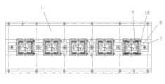
Fig. 1 is the structural representation of the specific embodiment of the invention;
Fig. 2 is schematic top plan view shown in Figure 1;
Fig. 3 is that schematic diagram is looked on a left side shown in Figure 1;
Fig. 4 is the local enlarged diagram of I section shown in Figure 1.
The specific embodiment
Shown in Fig. 1,2,3,4: 1 is clamp body, the rotary oil cylinder 7 that joins with hydraulic control device is installed at clamp body 1, the quantity of rotary oil cylinder 7 is 6 and arranged in a straight line on clamp body 1, each rotary oil cylinder 7 connects a pressure arm 8, the pressure arm 8 that turns oil cylinder 7 connections that is positioned at two ends is single armed, the pressure arm 8 that rotary oil cylinder 7 in the middle of being positioned at connects is both arms, and namely the both sides pressure arm is symmetrical arranged.By supporting seat 4 pull bar 5 is installed on clamp body 1, supporting seat 4 is fixedly connected on the clamp body 1, is provided with axle sleeve between supporting seat 4 and pull bar 5, is convenient to moving axially of pull bar 5.Pull bar 5 is consistent with the orientation of rotary oil cylinder 7.
Piston rod in the right-hand member of pull bar 5 and the pull bar oil cylinder 6 joins, concrete connected mode is that the right-hand member at pull bar 5 is processed with notch, the nut 12 of connecting bolt 11 terminations is positioned at notch, and connecting bolt 11 is threaded with piston rod end in the pull bar oil cylinder 6, and tightens fixing with nut 10.Pull bar 5 can be many and join end to end and connect the mode that can adopt pull bar 5 right-hand members to be connected with piston rod during connection.
Pull bar oil cylinder 6 is bolted to connection on clamp body 1.
Be set with 6 contiguous blocks 3 on the pull bar 5, be respectively equipped with right when plate 13 and right baffle-plate 15 on two lateral bracing struts 5 of each contiguous block 3, pull bar 5 is set with spring 14 between right baffle-plate 15 and contiguous block 3, each contiguous block 3 all is connected with saddle 2, for being slidingly connected, this is slidingly connected as dovetail groove type is slidingly connected between saddle 2 and the clamp body 1, and pull bar 5 is positioned at the below on plane on the clamp body 1, clamp body 1 is provided with hole 19, contiguous block 3 from the hole 19 protrude upward and with saddle 2 join (referring to Fig. 3).Saddle 2 tops have been bolted to connection workpiece centre locating piece 16.A side that is positioned at each rotary oil cylinder 7 at clamp body 1 is fixed with locating dowel 18 and workpiece support piece 17.
During use, each workpiece 9 places on the workpiece support piece 17, driving pull bar 5 by fluid pressure drive device moves axially, spring 14 leans contiguous block 3 and moves, make saddle 2 and workpiece centre locating piece 16 and workpiece 9 move thereupon and lean against on the locating dowel 18, because the adjusting of spring 14 elastic force is arranged, each workpiece 9 is leaned against on the locating dowel 18 simultaneously, then drive pressure arm 8 by rotary oil cylinder 7 workpiece 9 is compressed.A plurality of workpiece can be located simultaneously, and accurately and reliably, clamping force is even, improve the machining accuracy of workpiece, are suitable for the needs of production line beat.Simple in structure, easy to operate, time saving and energy saving.
Claims (3)
1. a lathe is with multi-work piece Flexible Fixturing device, comprise clamp body (1), at clamp body (1) rotary oil cylinder (7) is installed, rotary oil cylinder (7) connects pressure arm (8), it is characterized in that: (7) at least two of described rotary oil cylinders are also upper arranged in a straight line at clamp body (1), by supporting seat (4) pull bar (5) is installed at clamp body (1), pull bar (5) is consistent with the orientation of rotary oil cylinder (7), piston rod in pull bar (5) and the pull bar oil cylinder (6) joins, pull bar oil cylinder (6) is fixedly connected on the clamp body (1), be set with at least two contiguous blocks (3) on the pull bar (5), be respectively equipped with right when plate (13) and right baffle-plate (15) on two lateral bracing struts (5) of contiguous block (3), pull bar (5) is set with spring (14) between right baffle-plate (15) and contiguous block (3), each contiguous block (3) all is connected with saddle (2), between saddle (2) and the clamp body (1) for being slidingly connected, there is workpiece centre locating piece (16) saddle (2) top, is fixed with locating dowel (18) and workpiece support piece (17) at clamp body (1).
2. lathe according to claim 1 is with multi-work piece Flexible Fixturing device, it is characterized in that: described pull bar (5) is positioned at the below on the upper plane of clamp body (1), clamp body (1) is provided with hole (19), and (19) protrude upward and join with described saddle (2) described contiguous block (3) from the hole.
3. lathe according to claim 2 is characterized in that with multi-work piece Flexible Fixturing device: being slidingly connected between described saddle (2) and the clamp body (1) is slidingly connected for dovetail groove type.
Priority Applications (1)
| Application Number | Priority Date | Filing Date | Title |
|---|---|---|---|
| CN201210116639.7A CN102848241B (en) | 2012-04-20 | 2012-04-20 | Lathe multi-work piece Flexible Fixturing device |
Applications Claiming Priority (1)
| Application Number | Priority Date | Filing Date | Title |
|---|---|---|---|
| CN201210116639.7A CN102848241B (en) | 2012-04-20 | 2012-04-20 | Lathe multi-work piece Flexible Fixturing device |
Publications (2)
| Publication Number | Publication Date |
|---|---|
| CN102848241A true CN102848241A (en) | 2013-01-02 |
| CN102848241B CN102848241B (en) | 2015-11-11 |
Family
ID=47395429
Family Applications (1)
| Application Number | Title | Priority Date | Filing Date |
|---|---|---|---|
| CN201210116639.7A Expired - Fee Related CN102848241B (en) | 2012-04-20 | 2012-04-20 | Lathe multi-work piece Flexible Fixturing device |
Country Status (1)
| Country | Link |
|---|---|
| CN (1) | CN102848241B (en) |
Cited By (5)
| Publication number | Priority date | Publication date | Assignee | Title |
|---|---|---|---|---|
| CN103722421A (en) * | 2013-12-26 | 2014-04-16 | 上海戈吕克机械制造有限公司 | Drilling tool for thread sleeves of car trailing hooks |
| CN103990993A (en) * | 2014-05-14 | 2014-08-20 | 安徽机电职业技术学院 | Rotational multi-workpiece clamping and multi-station pneumatic clamp |
| CN104842195A (en) * | 2015-04-29 | 2015-08-19 | 佛山市普拉迪数控科技有限公司 | Clamping clamp for machining I-steel or channel steel |
| CN109304632A (en) * | 2017-07-26 | 2019-02-05 | 福士瑞精密工业(郑州)有限公司 | Clamping device |
| CN115781509A (en) * | 2022-11-15 | 2023-03-14 | 方华智能装备(秦皇岛)股份有限公司 | A flexible multi-workpiece clamping device for grinding operations |
Citations (5)
| Publication number | Priority date | Publication date | Assignee | Title |
|---|---|---|---|---|
| CN101722431A (en) * | 2008-10-31 | 2010-06-09 | 吴江市吴刚冲压机械有限公司 | Multi-station drilling jig |
| CN102198706A (en) * | 2011-05-12 | 2011-09-28 | 无锡机床股份有限公司 | Workpiece clamping mechanism of multi-wire cutting machine |
| CN202053094U (en) * | 2011-04-28 | 2011-11-30 | 浙江亿洋工具制造有限公司 | Clamp for machining slotted hole of ratchet wrench |
| DE202012001539U1 (en) * | 2012-02-15 | 2012-03-14 | Hohenstein Vorrichtungsbau Und Spannsysteme Gmbh | Self-sufficient hydraulic clamping pallet |
| CN202655960U (en) * | 2012-04-20 | 2013-01-09 | 大连华根机械有限公司 | Multi-workpiece flexible clamping device for machine tool |
-
2012
- 2012-04-20 CN CN201210116639.7A patent/CN102848241B/en not_active Expired - Fee Related
Patent Citations (5)
| Publication number | Priority date | Publication date | Assignee | Title |
|---|---|---|---|---|
| CN101722431A (en) * | 2008-10-31 | 2010-06-09 | 吴江市吴刚冲压机械有限公司 | Multi-station drilling jig |
| CN202053094U (en) * | 2011-04-28 | 2011-11-30 | 浙江亿洋工具制造有限公司 | Clamp for machining slotted hole of ratchet wrench |
| CN102198706A (en) * | 2011-05-12 | 2011-09-28 | 无锡机床股份有限公司 | Workpiece clamping mechanism of multi-wire cutting machine |
| DE202012001539U1 (en) * | 2012-02-15 | 2012-03-14 | Hohenstein Vorrichtungsbau Und Spannsysteme Gmbh | Self-sufficient hydraulic clamping pallet |
| CN202655960U (en) * | 2012-04-20 | 2013-01-09 | 大连华根机械有限公司 | Multi-workpiece flexible clamping device for machine tool |
Cited By (7)
| Publication number | Priority date | Publication date | Assignee | Title |
|---|---|---|---|---|
| CN103722421A (en) * | 2013-12-26 | 2014-04-16 | 上海戈吕克机械制造有限公司 | Drilling tool for thread sleeves of car trailing hooks |
| CN103722421B (en) * | 2013-12-26 | 2016-09-14 | 上海戈吕克机械制造有限公司 | A kind of Drilling operation frock of automobile tow hook thread bush |
| CN103990993A (en) * | 2014-05-14 | 2014-08-20 | 安徽机电职业技术学院 | Rotational multi-workpiece clamping and multi-station pneumatic clamp |
| CN104842195A (en) * | 2015-04-29 | 2015-08-19 | 佛山市普拉迪数控科技有限公司 | Clamping clamp for machining I-steel or channel steel |
| CN109304632A (en) * | 2017-07-26 | 2019-02-05 | 福士瑞精密工业(郑州)有限公司 | Clamping device |
| CN109304632B (en) * | 2017-07-26 | 2019-10-08 | 福士瑞精密工业(郑州)有限公司 | Clamping device |
| CN115781509A (en) * | 2022-11-15 | 2023-03-14 | 方华智能装备(秦皇岛)股份有限公司 | A flexible multi-workpiece clamping device for grinding operations |
Also Published As
| Publication number | Publication date |
|---|---|
| CN102848241B (en) | 2015-11-11 |
Similar Documents
| Publication | Publication Date | Title |
|---|---|---|
| CN202219412U (en) | Multipurpose horizontal clamping apparatus for hydraulic milling machine | |
| CN102990433B (en) | The auxiliary locator of machine vice | |
| CN102873563A (en) | Shell-class machine tool fixture | |
| CN102848241B (en) | Lathe multi-work piece Flexible Fixturing device | |
| CN217551859U (en) | Fire engine movable leg machine tooling anchor clamps | |
| CN103465074B (en) | Splined hub boring mesopore air-actuated jaw | |
| CN102501109A (en) | Fixture for machining positioning holes of hydraulic pump body | |
| CN202162440U (en) | Piston rod milling tool | |
| CN202655960U (en) | Multi-workpiece flexible clamping device for machine tool | |
| CN102601569A (en) | Welding fixture for transverse side rod support assemblies | |
| CN203622020U (en) | Pneumatic tool clamp for machining plate type part through hole | |
| CN202162590U (en) | Workpiece clamping device for milling end surfaces of workpieces | |
| CN105666211A (en) | Multipurpose hydraulic vice and using method thereof | |
| CN204171735U (en) | A kind of Quick-action bench vice | |
| CN203076925U (en) | Clamp for machining counterbored hole of connecting rod and oil hole on engine | |
| CN104308427A (en) | Hand-fed air-retracted connecting rod mechanism | |
| CN103028979A (en) | Tool | |
| CN206912986U (en) | Mechanical-hydraulic dual drive precision flatnosed pliers | |
| CN106670535A (en) | Drill machine tool for four-cylinder exhaust pipe | |
| CN104669005A (en) | Main chain link fixture of chain | |
| CN202655961U (en) | Drilling clamp for flange hole of water valve | |
| CN103464944A (en) | Soldering and locating device | |
| CN203566376U (en) | Clamping tool for vertical machining center | |
| CN102179712B (en) | Flat-milling tooling for piston rod of shock absorber for automobile | |
| CN222857158U (en) | A main valve frame welding clamping tool |
Legal Events
| Date | Code | Title | Description |
|---|---|---|---|
| C06 | Publication | ||
| PB01 | Publication | ||
| C10 | Entry into substantive examination | ||
| SE01 | Entry into force of request for substantive examination | ||
| C14 | Grant of patent or utility model | ||
| GR01 | Patent grant | ||
| CF01 | Termination of patent right due to non-payment of annual fee |
Granted publication date: 20151111 Termination date: 20160420 |
|
| CF01 | Termination of patent right due to non-payment of annual fee |