CN102831874A - Video signal processing circuit, video signal processing method, display device, and electronic apparatus - Google Patents
Video signal processing circuit, video signal processing method, display device, and electronic apparatus Download PDFInfo
- Publication number
- CN102831874A CN102831874A CN2012101950642A CN201210195064A CN102831874A CN 102831874 A CN102831874 A CN 102831874A CN 2012101950642 A CN2012101950642 A CN 2012101950642A CN 201210195064 A CN201210195064 A CN 201210195064A CN 102831874 A CN102831874 A CN 102831874A
- Authority
- CN
- China
- Prior art keywords
- frame
- control
- equivalent
- integrated value
- time
- Prior art date
- Legal status (The legal status is an assumption and is not a legal conclusion. Google has not performed a legal analysis and makes no representation as to the accuracy of the status listed.)
- Pending
Links
Images


Classifications
-
- G—PHYSICS
- G09—EDUCATION; CRYPTOGRAPHY; DISPLAY; ADVERTISING; SEALS
- G09G—ARRANGEMENTS OR CIRCUITS FOR CONTROL OF INDICATING DEVICES USING STATIC MEANS TO PRESENT VARIABLE INFORMATION
- G09G3/00—Control arrangements or circuits, of interest only in connection with visual indicators other than cathode-ray tubes
- G09G3/20—Control arrangements or circuits, of interest only in connection with visual indicators other than cathode-ray tubes for presentation of an assembly of a number of characters, e.g. a page, by composing the assembly by combination of individual elements arranged in a matrix no fixed position being assigned to or needed to be assigned to the individual characters or partial characters
-
- G—PHYSICS
- G09—EDUCATION; CRYPTOGRAPHY; DISPLAY; ADVERTISING; SEALS
- G09G—ARRANGEMENTS OR CIRCUITS FOR CONTROL OF INDICATING DEVICES USING STATIC MEANS TO PRESENT VARIABLE INFORMATION
- G09G2320/00—Control of display operating conditions
- G09G2320/06—Adjustment of display parameters
- G09G2320/0626—Adjustment of display parameters for control of overall brightness
-
- G—PHYSICS
- G09—EDUCATION; CRYPTOGRAPHY; DISPLAY; ADVERTISING; SEALS
- G09G—ARRANGEMENTS OR CIRCUITS FOR CONTROL OF INDICATING DEVICES USING STATIC MEANS TO PRESENT VARIABLE INFORMATION
- G09G2330/00—Aspects of power supply; Aspects of display protection and defect management
- G09G2330/02—Details of power systems and of start or stop of display operation
- G09G2330/021—Power management, e.g. power saving
-
- G—PHYSICS
- G09—EDUCATION; CRYPTOGRAPHY; DISPLAY; ADVERTISING; SEALS
- G09G—ARRANGEMENTS OR CIRCUITS FOR CONTROL OF INDICATING DEVICES USING STATIC MEANS TO PRESENT VARIABLE INFORMATION
- G09G2360/00—Aspects of the architecture of display systems
- G09G2360/16—Calculation or use of calculated indices related to luminance levels in display data
Abstract
The invention provides a video signal processing circuit, a video signal processing method, a display device, and an electronic apparatus. The video signal processing circuit includes: a control unit that calculates a luminance integrated value on the basis of an input video signal and performs luminance control for the video signal on the basis of the calculated luminance integrated value, wherein the control unit calculates the luminance integrated value at a period shorter than time equivalent to one frame.
Description
Technical field
The disclosure relates to video processing circuit, video signal processing method, display device and electronic equipment; More particularly, the disclosure relate to the brilliance control that is used to carry out vision signal video processing circuit and video signal processing method, comprise the display device of this video processing circuit and the electronic equipment that comprises this display device.
Background technology
When the high brightness vision signal is input to display device, be input to the vision signal of display panel and the electric current of the optoelectronic components that inhibition flows to pixel through control, can reduce current drain (power consumption).
Past; The video processing circuit of carrying out this control calculates the brightness integrated value of each screen (frame) according to incoming video signal; Amplitude according to the brightness integrated value control of video signal that is calculated; And the vision signal that will pass through amplitude control is provided to display device (for example, referring to JP-A-2003-255901)
Summary of the invention
Video processing circuit according to prior art calculates the brightness integrated value according to incoming video signal to each frame, and carries out the brilliance control of vision signal according to result of calculation.Therefore, because the result of calculation of previous frame is reflected in the control of present frame, so when result of calculation is reflected in the brilliance control, existence is equivalent to the time delay of a frame usually.Therefore, in the period of a frame that is used to calculate the brightness integrated value, be difficult to carry out the brilliance control of vision signal, that is, reduce the control of current drain.
Therefore, be desirable to provide video processing circuit and the video signal processing method that can control in the period shorter about the brilliance control of vision signal than the time that is equivalent to a frame, comprise the display device of this video processing circuit and the electronic equipment that comprises this display device.
Embodiment of the present disclosure relates to video processing circuit, and it carries out the brilliance control of vision signal according to incoming video signal calculating brightness integrated value and according to the brightness integrated value of calculating.This video processing circuit calculates the brightness integrated value in the period shorter than the time that is equivalent to a frame.
In display device, video processing circuit can be with acting on the circuit of handling the vision signal that is input to display device.In various electronic equipments, comprise that the display device of video processing circuit can be as the display unit of electronic equipment.
Because the period with shorter than the time that is equivalent to a frame is calculated the brightness integrated value, so can carry out brilliance control with the period shorter than the time that is equivalent to a frame according to the vision signal of result of calculation.Therefore, can control,, and need not to wait for the time (period of a frame) that is equivalent to a frame with the current drain of reduction display device.
According to embodiment of the present disclosure, can under the situation of not waiting for the time that is equivalent to a frame, carry out the brilliance control of vision signal.Therefore, can be implemented in the control of the current drain (power consumption) under the situation of the time delay that is not equivalent to a frame.
Description of drawings
Fig. 1 is the block diagram according to the circuit arrangement of the video processing circuit of disclosure embodiment;
Fig. 2 is the block diagram of particular example of the configuration of row average integral current calculation unit;
Fig. 3 is the block diagram of particular example of the configuration of row gain calculating unit;
Fig. 4 is the block diagram of particular example of the configuration of row amplitude control module;
Fig. 5 is the synoptic diagram that is used to explain according to the operation of the video processing circuit of particular example;
Fig. 6 is the block diagram according to the circuit arrangement of the video processing circuit of modification;
Fig. 7 is a skeleton view of having used the outward appearance of televisor of the present disclosure;
Fig. 8 A and Fig. 8 B are the skeleton views of having used the outward appearance of digital camera of the present disclosure, and wherein Fig. 8 A is the skeleton view of the digital camera in the past looked sideways, and Fig. 8 B be from after the skeleton view of the digital camera looked sideways;
Fig. 9 is a skeleton view of having used the outward appearance of notebook-sized personal computer of the present disclosure;
Figure 10 is a skeleton view of having used the outward appearance of video camera of the present disclosure; And
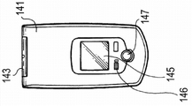
Figure 11 A to Figure 11 G is an external view of having used cellular phone of the present disclosure; Wherein Figure 11 A is the front view that is in the cellular phone under the open mode, and Figure 11 B is the side view that is in the cellular phone under the open mode, and Figure 11 C is the front view that is in the cellular phone under the closure state; Figure 11 D is the left side view of cellular phone; Figure 11 E is the right side view of cellular phone, and Figure 11 F is the vertical view of cellular phone, and Figure 11 G is the upward view of cellular phone.
Embodiment
Below with reference to accompanying drawing illustrated in detail exemplary embodiments of the present disclosure.Order to describe below makes an explanation.
1. the introduction of embodiment
1-1. circuit arrangement
1-2. circuit operation
2. modification
3. electronic equipment
4. configuration of the present disclosure
< the 1. explanation of embodiment >
Video processing circuit according to disclosure embodiment is provided between signal source and the display device (perhaps display panel).Video processing circuit is handled from the vision signal (incoming video signal) of signal source input, and vision signal is provided to display device.Video processing circuit calculates the brightness integrated value according to incoming video signal, and through carrying out brilliance control according to the brightness integrated value control of video signal that calculates.Usually, video processing circuit is called as ABL (automatic brightness limiter) circuit.
Video processing circuit according to this embodiment comprises control module, and it calculates the brightness integrated value with the period shorter than the time that is equivalent to a frame (a screen), and according to the brightness integrated value control of video signal that calculates.When brightness integrated value during greater than control target, control module is controlled to be little value with vision signal.
The period shorter than the time that is equivalent to a frame can be unit with the time that is equivalent to delegation's (pixel column).In this case, the period shorter than the time that is equivalent to a frame can be the time that is equivalent to delegation, also can be the time that is equivalent to multirow.The period shorter than the time that is equivalent to a frame be not limited to the time that is equivalent to delegation be unit, and can be with the time than shorter being equivalent to a bit of the time that is equivalent to delegation (pixel) be unit.
Video processing circuit according to this embodiment can comprise two control system, that is, and and first control system and second control system.First control system is to be used for calculating the brightness integrated value with the time period that is equivalent to a frame, and according to the control system of this brightness integrated value control of video signal.Second control system is the control system that is equivalent to control module, and is used for calculating the brightness integrated value with the period shorter than the time that is equivalent to a frame, and according to this brightness integrated value control of video signal.
In second control system, the period shorter than the time that is equivalent to a frame can be with the time that is equivalent to delegation be unit.In this case, the period shorter than the time that is equivalent to a frame can be the time that is equivalent to delegation, also can be the time that is equivalent to multirow.The period shorter than the time that is equivalent to a frame be not limited to the time that is equivalent to delegation be unit, and can be that time than shorter being equivalent to a bit of the time that is equivalent to delegation (pixel) is unit.
About the relation of the step between first control system and second control system, preferably second control system is arranged on the back level of first control system.In other words; In video processing circuit according to this embodiment; Except well-known first control system, be used for to calculate the brightness integrated value than shorter period time that is equivalent to a frame and to be arranged in the back level of first control system according to second control system of this brightness integrated value control of video signal.In this case, about the control target of first control system and second control system, the control target of second control system is set to the value higher than the control target of first control system.
[1-1. circuit arrangement]
Fig. 1 is the block diagram according to the circuit arrangement of the video processing circuit of present embodiment.
In Fig. 1, be arranged between signal source (not shown) and the display device 20 according to the video processing circuit 10 of this embodiment.Video processing circuit 10 is handled the incoming video signal that provides from signal source, and vision signal is provided to display device 20.The video processing circuit 10 that is commonly referred to the ABL circuit preferably includes two control system, that is, and and the combination of first control system 30 and second control system 40.Second control system 40 is arranged on the back level of first control system 30.
First control system 30 comprises: frame average current computing unit 31, frame gain calculating unit 32 and frame video signal control module 33.First control system 30 is calculated the brightness integrated value with period time that is equivalent to a frame (screen), and comes the control of video signal according to the brightness integrated value that calculates.First control system 30 is equivalent to the well-known ABL circuit that carries out vision signal control (brilliance control) with the time period that is equivalent to a frame.
In first control system 30, frame average current computing unit 31 calculates the average current of frame for every frame.This frame average current is equivalent to the brightness integrated value of a frame.In other words, frame average current computing unit 31 calculates the frame average current that is equivalent to the brightness integrated value with the time period that is equivalent to a frame.
Frame gain calculating unit 32 reference control desired values (frame control target) calculate gain about the vision signal of frame (below be called " frame gain ") according to the frame average current that is calculated by frame average current computing unit 31.Frame video signal control module 33 gains according to the frame that is calculated by frame gain calculating unit 32 and controls the vision signal of next frame.
Second control system 40 comprises: row average integral current calculation unit 41, row gain calculating unit 42 and row vision signal control module 43.Second control system 40 is calculated the brightness integrated value with the time period that is equivalent to delegation's (pixel column), and according to the amplitude of the brightness integrated value control of video signal that calculates.Specifically, when the brightness integrated value greater than the control target of explained later when (surpassing control target), second control system 40 is controlled to be little value with the amplitude of vision signal.Second control system 40 is according to characteristic of the present disclosure.
Below with the capable average integral current calculation unit of specific explanations 41, row gain calculating unit 42 and row vision signal control module 43 configuration separately.
(row average integral current calculation unit)
Fig. 2 is the block diagram of particular example of the configuration of row average integral current calculation unit 41.As shown in Figure 2, row average integral current calculation unit 41 comprises: average signal computing unit 411, average current computing unit 412 and average integral current calculation unit 413.Row average integral current calculation unit 41 is to go the period operation of (horizontal scanning period) executive circuit.
Be expert in the average integral current calculation unit 41, average signal computing unit 411 is according to calculating average signal level by the vision signal of frame video signal control module 33 controls for every row.Average current computing unit 412 calculates the average current corresponding to average signal level according to the average signal level that is calculated by average signal computing unit 411 for every row.
Average integral current calculation unit 413 is till current line; Average current to every row of being calculated by average current computing unit 412 carries out integration; And the integral mean electric current is provided to the capable gain calculating unit 42 at next stage, as row average integral electric current.Row average integral electric current is equivalent to the brightness integrated value up to every row.In other words, average integral current calculation unit 413 calculates the capable average integral electric current that is equivalent to the brightness integrated value with the period shorter than the time that is equivalent to a frame.
(row gain calculating unit)
Fig. 3 is the block diagram of particular example of the configuration of row gain calculating unit 42.As shown in Figure 3, row gain calculating unit 42 comprises that electric current comparing unit 421 is with gain calculating unit 422 and to go period executive circuit operation.
In the gain calculating of the being expert at unit 42, electric current comparing unit 421 will be compared by capable average integral current calculation unit 41 capable average integral electric current that calculates and the control target that is provided with in advance (row control target) in prime.The capable control target of second control system 40 is set to the value bigger than the frame control target of first control system 30 (its reason of explained later).Electric current comparing unit 421 will be equal to or less than control target about row average integral electric current and still give the gain calculating unit 422 at next stage above the comparative result of control target.
For example; Comparative result according to electric current comparing unit 421; When row average integral electric current is equal to or less than control target; Gain calculating unit 422 will gain " 1 " be provided at the capable vision signal control module of next stage 43 as the row gain, and when row average integral electric current surpasses control target, will gain " 0 " is provided to go in capable vision signal control module 43 conducts of next stage and gains.
(row vision signal control module)
Fig. 4 is the block diagram of particular example of the configuration of row vision signal control module 43.As shown in Figure 4, row vision signal control module 43 comprises multiplier 431.Row vision signal control module 43 is to go period executive circuit operation.Multiplier 431 receives the input by the vision signal of frame video signal control module 33 controls, and this incoming video signal multiply by the row gain that provides from row gain calculating unit 42, with the control of video signal.
The vision signal of being expert at control module 43 promptly in the multiplier 431, is carried out brilliance control according to the control of vision signal.Be provided to display device 20 from the vision signal (outputting video signal) of multiplier 431 outputs.
[1-2. circuit operation]
To explain circuit operation below according to the video processing circuit 10 of this embodiment with top configuration of explaining.
(first control system)
The vision signal of supplying with from the signal source (not shown) at first is input to first control system 30.The video signal flow that is input to first control system 30 is divided into two vision signals.One directly sends to frame video signal control module 33, and another sends to frame average current computing unit 31.
The vision signal that sends to frame video signal control module 33 is input to second control system 40 at next stage after the control that experience frame video signal control module 33 is carried out according to the frame gain that is calculated by frame gain calculating unit 32.On the other hand, the vision signal that sends to frame average current computing unit 31 is used to calculate the frame average current till the vision signal of a frame finishes.
The stage of frame average current computing unit 31 when the vision signal of a frame finishes confirmed the average current of a frame,, is equivalent to the frame average current of brightness integrated value of the vision signal of a frame that is.Frame average current computing unit 31 sends to frame gain calculating unit 32 with the frame average current of confirming.Frame gain calculating unit 32 utilizes the frame control target as the control benchmark, confirms the frame gain according to the frame average current that sends from frame average current computing unit 31.Frame gain calculating unit 32 sends to frame video signal control module 33 with the frame gain of confirming.
Obvious in the superincumbent explanation, in first control system 30, calculate the frame average current that is equivalent to the brightness integrated value about a particular frame; Confirm the frame gain according to the frame average current; And the frame gain is reflected in the control to the vision signal of next frame, that is, and and in the brilliance control.
Therefore, even the frame average current surpasses the frame control target in a particular frame, the vision signal of this frame is not used brilliance control yet, and the vision signal of next frame is used brilliance control.In other words, when the result of calculation of frame average current is reflected in the brilliance control, be equivalent to the time delay of a frame usually.Therefore, be difficult in the period of a frame, carry out the brilliance control of vision signal, that is, reduce the control of current drain (power consumption).
(second control system)
The vision signal of first control system, 30 controls is input to second control system 40.The video signal flow that is input to second control system 40 is divided into two vision signals.One directly sends to capable vision signal control module 43, and another sends to capable average integral current calculation unit 41.
The vision signal that sends to capable vision signal control module 43 outputs to the data driver (not shown) of the display device 20 that is positioned at the back level after having experienced by the control of row vision signal control module 43 according to the row gain of being calculated by row gain calculating unit 42.In this embodiment, going the vision signal of vision signal control module 43 control directly is provided to display device 20.Yet this vision signal can be provided to display device 20 through the signal processing circuit of carrying out the signal Processing that requires.
On the other hand, the vision signal that sends to capable average integral current calculation unit 41 is used to calculate the capable average integral electric current till the vision signal of delegation finishes.Row average integral current calculation unit 41 calculates the integration current of current line in the stage that the vision signal of delegation finishes, and, is equivalent to the capable average integral electric current of the brightness integrated value of current line that is.Row average integral current calculation unit 41 will be gone the average integral electric current and sent to capable gain calculating unit 42.
Row gain calculating unit 42 utilizes the row control target as the control benchmark, confirms the row gain according to the capable average integral electric current that sends from row average integral current calculation unit 41.Specifically, for example, when row average integral electric current is equal to or less than control target, go to gain and be set to " 1 " in row gain calculating unit 42, and when row average integral electric current surpassed control target, the gain of going was set to " 0 ".The row gain that row gain calculating unit 42 will be confirmed like this sends to capable vision signal control module 43.
As stated, in first control system 30, till a frame end, be difficult to carry out brilliance control.On the other hand, in second control system 40, calculate the capable average integral electric current that is equivalent to the brightness integrated value with behavior unit; Confirm the row gain according to row average integral electric current; The row gain is reflected in the control of vision signal, that is, and and in the brilliance control of the next one and subsequent rows.Therefore, can need not to wait for the period of a frame, that is, in the unit shorter, carry out brilliance control than the time that is equivalent to a frame.
Through carrying out the control of vision signal, that is, brilliance control can suppress to flow to the electric current of optoelectronic components of the pixel of display device 20.Therefore, can reduce the current drain (power consumption) of display device 20.In other words, the brightness of control of video signal is exactly the current drain of control display device 20.
(particular example)
The research particular example, in this particular example, the average signal level of incoming video signal promptly, is transferred to duty to the control of vision signal from off working state from low state transitions to higher state and to the control of current drain.
At the time point when frame begins under the situation of the control of vision signal being transferred to duty from off working state, the value that average signal level is in low state is set to the frame gain of first control system 30.Therefore, frame video signal control module 33 utilizes the frame gain of this value to carry out control.Specifically, as shown in Figure 5, the frame gain when duty is transferred in control from off working state before the frame is for example 1.0 the time, and the frame gain of present frame also remains on 1.0.
In other words, 33 outputs of frame video signal control module are transferred to the duty identical vision signal of vision signal before with control from off working state.Therefore, in only by the control of carrying out as first control system 30 of prior art, reckon without the fact of average signal level from low state transitions to higher state of incoming video signal, not controlled vision signal is input to display device 20.Therefore, before controlling a frame of transferring to duty from off working state and in the period of maximum two frames afterwards, produce excess current.Till the period of two frames finishes, be difficult to current drain is carried out control.
On the other hand, in this embodiment, second control system 40 is arranged in the back level of first control system 30.Carry out the control of the vision signal of every row in second control system 40.Therefore, as shown in Figure 5 when being in control and transferring to frame middle row average integral electric current under the situation of duty from off working state and surpass the row control target, for example, being about to the end gain from next line is set to 0.0.When the row gain is set to 0.0,, show so in the period of going to the end, carry out black (black-tape) from next line because the signal level of vision signal is reduced to 0.
Therefore, can carry out the brilliance control of vision signal with behavior unit, and need not to wait for that the period of a frame finishes.Therefore, can in maximum two frames, suppress excess current.When row average integral electric current surpasses the row control target, carry out black display.Yet this only is an example.For example, can carry out grey shows.
Time point when the average signal level of incoming video signal frame end and the next frame from low state transitions to higher state begins; As shown in Figure 5, the value of high state average signal level, promptly; The value of formerly calculating in the frame (for example, 0.4) is set to the frame gain.Therefore, frame video signal control module 33 utilizes the frame gain of this value to control.
The frame of the value of in other words, calculating in frame video signal control module 33 output and the frame formerly corresponding small video signal that gains.Therefore, be arranged in second control system 40 of back level, the amplitude of incoming video signal is little, and control target is provided with greater than the control target of first control system 30.Therefore, after this, do not carry out control, that is, change to off working state with the control of behavior unit with behavior unit.
In Fig. 5, show the instantaneous display panel current drain of special time.When display panel drives with row order, and display image is when being raster image (uniform image on the whole surface), and Fig. 5 illustrates its work behavior.In natural image such as broadcast singal, the complicated non-linear behavior of curve indication shown in Figure 5.
(effect and effect)
As stated, utilize video processing circuit 10, average signal level that being controlled at of carrying out of second control system 40 the is in incoming video signal frame under from low state transitions to the situation of higher state, work according to this embodiment.In the frame outside this frame, the control of second control system 40 is not worked, and the Control work of first control system 30.
Therefore, can carry out the brilliance control of vision signal, and need not to wait for the time that is equivalent to a frame.Therefore, can realize the control of current drain (power consumption) and be not equivalent to the delay of a frame, carry out simultaneously and the identical Current Control of system of passing by.Can prevent in maximum two frames, excess current to take place.Depend on the electronic equipment that display device 20 has been installed, be provided with the upper limit of the power consumption of a frame.Therefore, owing to can control the power consumption of a frame, so display device 20 is fit to be applied to be provided with the electronic equipment of the power consumption upper limit of a frame, particularly, portable electric appts.
Mention in passing, adopt the method for utilizing frame memory to carry out brilliance control, also can under the situation of not waiting for the time that is equivalent to a frame, carry out the brilliance control of vision signal.Yet cost raises when using frame memory.On the other hand, when the configuration of adopting according to the video processing circuit 10 of this embodiment, that is, when comprising the configuration of first control system 30 and second control system 40, need not use expensive frame memory.Therefore, the advantage of existence is can be with the implemented with low cost its intended purposes.
About being that unit carries out first control system 30 of control and the layout of carrying out second control system 40 of control with behavior unit with the frame, require first control system 30 to be arranged in prime, and second control system 40 is arranged in the arrangement relation of back level.This is because if second control system 40 is arranged in prime, then frequently carry out the control of second control system 40, and when each execution is controlled, all show black-tape on the screen.Therefore, picture quality reduces.
On the other hand, if second control system 40 is arranged on back level, then 40 pairs of second control system vision signal that is positioned at first control system, 30 controls of prime is controlled.Therefore, the defective that when second control system 40 is arranged in prime, occurs can not take place.In other words, first control system 30 is not carried out the control that the frame of amplitude control is used second control system 40.Therefore, even black-tape occurs, also only at this frame black-tape appears.
Mention in passing, for the control of only first control system, 30 unsteered frames being used second control system 40, control target that need second control system 40 is set to the value higher than the control target of first control system 30.
2. modification
In the examples of circuits of explaining, adopt second control system 40 to control the configuration of (brilliance control) with the time period that is equivalent to delegation's (that is, for each row) in the above.Yet, also can be employed in the configuration that time period of being equivalent to multirow (that is, for every a plurality of row) controls.
Can be with the time that is equivalent to a bit (pixel) unit (promptly; To every bit or every a plurality of points) carry out the control of second control system 40; And be not that unit (that is, to each row or every multirow) carries out the control of second control system 40 with the time that is equivalent to delegation.Yet,, can carry out such as calculating row average integral electric current and the processing of calculating the row gain in the horizontal blanking period when with the time that is equivalent to delegation being unit when controlling.Therefore, and be that unit controls and compares with the time that is equivalent to a bit, be that unit controls with the time that is equivalent to delegation be favourable, because it need not be used for the special set time of computing.
(the amplitude control of some unit)
Fig. 6 is the block diagram according to the circuit arrangement of the video processing circuit of the modification that every bit is controlled.In the figure, utilize identical Reference numeral or symbolic representation and the equivalent parts of parts shown in Figure 1.
In video processing circuit 10 ' according to this modification, to compare with video processing circuit 10 according to the embodiment of top explanation, the configuration of second control system 40 ' is different with the configuration of second control system 40.Specifically; The time period of utilizing some current calculation unit 44, some gain calculating unit 45 and point video signal control module 46 to replace row average integral current calculation unit 41, row gain calculating unit 42 and row vision signal control module 43, the second control system 40 ' to be configured to be used for for example to be equivalent to any is controlled.
In second control system 40 '; When controlling with the time period that is equivalent to a bit; Point current calculation unit 44 detects the some electric current of the brightness that is equivalent to a pixel; And when controlling, detect the some average current of the brightness integrated value that is equivalent to a plurality of pixels with the time period that is equivalent to a plurality of points.Compare with controlling with behavior unit, utilizing with the point is second control system 40 ' that unit controls, and can consume with shorter period Control current.
(display device)
In the superincumbent explanation, be set to the external circuit of display device 20 according to the video processing circuit 10 or 10 ' of the modification of disclosure embodiment or embodiment.Yet display device 20 can be used as display panel and provides, and display panel 20 can be provided as display device (according to display device of the present disclosure) with video processing circuit 10 or 10 '.
As display device (panel) 20; Except well-known liquid crystal indicator (LCD) and well-known plasma display system (PDP); Also illustrate and comprise the current drives optoelectronic components; For example, as organic field luminescence (EL) display device of organic EL parts of the luminous component of pixel.The current drives optoelectronic components is the luminous component that its luminosity changes according to the current value that flows to device.As the current drives optoelectronic components, except organic EL parts, also for example clear inorganic EL parts, LED parts, semiconductor laser parts etc.
< electronic equipment >
Comprise that display device (according to display device of the present disclosure) according to the video processing circuit of the modification of the embodiment of the present disclosure of top explanation or embodiment can be applied to the display unit with the electronic equipment in the every field that the vision signal of its input or the vision signal that produces in it is shown as image or video.Specifically, can be according to display device of the present disclosure as digital camera for example, notebook-sized personal computer, such as the portable terminal of cellular phone and the display unit of video camera.
Can find out from the description that the modification of embodiment and embodiment is done, utilize according to video processing circuit of the present disclosure, can be in maximum two frames control power consumptions.Therefore; When comprising according to the display device of video processing circuit of the present disclosure as the display unit of the electronic equipment of the power consumption upper limit that wherein is provided with a frame; Because the power consumption of display device can be restricted to and be equal to or less than fixedly power consumption, so help to reduce the power consumption of electronic equipment.
Explained later has been used the particular example of electronic equipment of the present disclosure.
Fig. 7 is a skeleton view of having used the outward appearance of televisor of the present disclosure.Televisor according to this applying examples comprises the video display screen unit 101 that comprises front panel 102 and filter glass 103.Be used as video display screen unit 101 according to display device of the present disclosure.
Fig. 8 A and Fig. 8 B are the skeleton views of having used the outward appearance of digital camera of the present disclosure.Fig. 8 A is the skeleton view of the digital camera in the past looked sideways, and Fig. 8 B be from after the skeleton view of the digital camera looked sideways.Digital camera according to this applying examples comprises: the luminescence unit 111 that is used to glisten, display unit 112, menu switch 113 and shutter release button 114.Be used as display unit 112 according to display device of the present disclosure.
Fig. 9 is a skeleton view of having used the outward appearance of notebook-sized personal computer of the present disclosure.Notebook-sized personal computer according to this applying examples comprises in main body 121: the keyboard 122 of operation when input character etc. and the display unit 123 that is used for display image.Be used as display device 123 according to display device of the present disclosure.
Figure 10 is a skeleton view of having used the outward appearance of video camera of the present disclosure.Video camera according to this applying examples comprises: main unit 131, be positioned at main unit 131 the front side be used for the camera lens 132 that object takes, startup/shutdown switch 133 and the display unit 134 that when taking, uses.Be used as display device 134 according to display device of the present disclosure.
Figure 11 A to Figure 11 G is an external view of having used the portable terminal of for example cellular phone of the present disclosure.Figure 11 A is the front view that is in the cellular phone under the open mode; Figure 11 B is the side view that is in the cellular phone under the open mode; Figure 11 C is the front view that is in the cellular phone under the closure state, and Figure 11 D is the left side view of cellular phone, and Figure 11 E is the right side view of cellular phone; Figure 11 F is the vertical view of cellular phone, and Figure 11 G is the upward view of cellular phone.Cellular phone according to this applying examples comprises: upper case 141, lower case 142, coupling part (hinge portion) 143, display 144, slave display 145, picture lamp 146 and camera 147.Be used as display 144 and slave display 145 according to display device of the present disclosure.
< configuration 4. of the present disclosure >
(1) a kind of video processing circuit comprises according to incoming video signal and calculates the brightness integrated value and carry out the control module of the brilliance control of vision signal according to the brightness integrated value that calculates, wherein
Control module calculates the brightness integrated value with the period shorter than the time that is equivalent to a frame.
(2) according to (1) described video processing circuit, wherein, control module is in the brightness integrated value during greater than control target, and the amplitude of vision signal is controlled to be little value.
(3) according to (1) perhaps (2) described video processing circuit, wherein, the period shorter than the time that is equivalent to a frame is unit with the time that is equivalent to delegation.
(4) according to (3) described video processing circuit, wherein, the period shorter than the time that is equivalent to a frame is the time that is equivalent to delegation.
(5) according to (3) described video processing circuit, wherein, the period shorter than the time that is equivalent to a frame is the time that is equivalent to multirow.
(6) according to (1) perhaps (2) described video processing circuit, wherein, the period shorter than the time that is equivalent to a frame is unit with the time that is equivalent to a bit.
(7) a kind of video processing circuit comprises:
First control system is calculated the brightness integrated value with period time that is equivalent to a frame, and according to the brightness integrated value control of video signal that calculates; And
Second control system, with the period calculating brightness integrated value shorter than the time that is equivalent to a frame, and according to the brightness integrated value control of video signal that calculates.
(8) according to (7) described video processing circuit, wherein, first control system and second control system during greater than control target, are controlled to be little value with vision signal in the brightness integrated value.
(9) according to (7) perhaps (8) described video processing circuit, wherein, second control system is that unit calculates the brightness integrated value with the time that is equivalent to delegation.
(10) according to (9) described video processing circuit, wherein, second control system is calculated the brightness integrated value with the time period that is equivalent to delegation.
(11) according to (9) described video processing circuit, wherein, second control system is calculated the brightness integrated value with the time period that is equivalent to a plurality of row.
(12) according to (7) described video processing circuit, wherein, second control system is that unit calculates the brightness integrated value with the time that is equivalent to a bit.
(13) according to any one the described video processing circuit in (7) to (12), wherein, second control system is provided at the back level of first control system.
(14) according to (13) described video processing circuit, wherein, the control target of second control system is set to the value higher than the control target of first control system.
(15) a kind of video signal processing method is included in when calculating the brightness integrated value and carrying out the brilliance control of vision signal according to the brightness integrated value of calculating according to incoming video signal, calculates the brightness integrated value with the period shorter than the time that is equivalent to a frame.
(16) a kind of display device comprises according to incoming video signal to calculate the brightness integrated value than shorter period time that is equivalent to a frame and to carry out the control module of the brilliance control of vision signal according to the brightness integrated value that calculates.
(17) a kind of electronic equipment comprises comprising according to incoming video signal to calculate the brightness integrated value than shorter period time that is equivalent to a frame and to carry out the display device of control module of the brilliance control of vision signal according to the brightness integrated value that calculates.
The disclosure contains the relevant theme of theme that discloses with the JP2011-132006 japanese priority patent application of submitting to Jap.P. office on June 14th, 2011, comprises the full content of this patented claim by reference at this.
Those skilled in the art should be understood that according to designing requirement and other factors, it is contemplated that various modifications, combination, part combination and modification, yet they fall into all in appended claims or its equivalent scope.
Claims (17)
1. video processing circuit comprises:
Control module calculates the brightness integrated value and carries out the brilliance control of vision signal according to the brightness integrated value that is calculated according to incoming video signal, wherein
Said control module calculates the brightness integrated value with the period shorter than the time that is equivalent to a frame.
2. video processing circuit according to claim 1, wherein, said control module is in the brightness integrated value during greater than control target, and the amplitude of vision signal is controlled to be little value.
3. video processing circuit according to claim 1, wherein, the period shorter than the time that is equivalent to a frame is unit with the time that is equivalent to delegation.
4. video processing circuit according to claim 3, wherein, the period shorter than the time that is equivalent to a frame is the time that is equivalent to delegation.
5. video processing circuit according to claim 3, wherein, the period shorter than the time that is equivalent to a frame is the time that is equivalent to a plurality of row.
6. video processing circuit according to claim 1, wherein, the period shorter than the time that is equivalent to a frame is unit with the time that is equivalent to a bit.
7. video processing circuit comprises:
First control system is calculated the brightness integrated value with the time period that is equivalent to a frame, and is come the control of video signal according to the brightness integrated value of being calculated; And
Second control system calculating the brightness integrated value than shorter period time that is equivalent to a frame, and is come the control of video signal according to the brightness integrated value of being calculated.
8. video processing circuit according to claim 7, wherein, said first control system and said second control system during greater than control target, are controlled to be little value with vision signal in the brightness integrated value.
9. video processing circuit according to claim 7, wherein, said second control system is that unit calculates the brightness integrated value with the time that is equivalent to delegation.
10. video processing circuit according to claim 9, wherein, said second control system is calculated the brightness integrated value with the time period that is equivalent to delegation.
11. video processing circuit according to claim 9, wherein, said second control system is calculated the brightness integrated value with the time period that is equivalent to a plurality of row.
12. video processing circuit according to claim 7, wherein, said second control system is that unit calculates the brightness integrated value with the time that is equivalent to a bit.
13. video processing circuit according to claim 7, wherein, said second control system is provided at the back level of said first control system.
14. video processing circuit according to claim 13, wherein, the control target of said second control system is set to the value higher than the control target of said first control system.
15. a video signal processing method is included in when calculating the brightness integrated value and carrying out the brilliance control of vision signal according to the brightness integrated value that is calculated according to incoming video signal,
Period with shorter than the time that is equivalent to a frame is calculated the brightness integrated value.
16. a display device comprises:
Control module calculates the brightness integrated value according to incoming video signal with the period shorter than the time that is equivalent to a frame, and carries out the brilliance control of vision signal according to the brightness integrated value that is calculated.
17. an electronic equipment comprises:
Display device comprises according to incoming video signal to calculate the brightness integrated value than shorter period time that is equivalent to a frame and to carry out the control module of the brilliance control of vision signal according to the brightness integrated value that is calculated.
Applications Claiming Priority (2)
| Application Number | Priority Date | Filing Date | Title |
|---|---|---|---|
| JP2011132006A JP2013003238A (en) | 2011-06-14 | 2011-06-14 | Video signal processing circuit, video signal processing method, display device, and electronic apparatus |
| JP2011-132006 | 2011-06-14 |
Publications (1)
| Publication Number | Publication Date |
|---|---|
| CN102831874A true CN102831874A (en) | 2012-12-19 |
Family
ID=47334973
Family Applications (1)
| Application Number | Title | Priority Date | Filing Date |
|---|---|---|---|
| CN2012101950642A Pending CN102831874A (en) | 2011-06-14 | 2012-06-13 | Video signal processing circuit, video signal processing method, display device, and electronic apparatus |
Country Status (3)
| Country | Link |
|---|---|
| US (1) | US8896758B2 (en) |
| JP (1) | JP2013003238A (en) |
| CN (1) | CN102831874A (en) |
Families Citing this family (5)
| Publication number | Priority date | Publication date | Assignee | Title |
|---|---|---|---|---|
| JP5221780B1 (en) * | 2012-02-03 | 2013-06-26 | シャープ株式会社 | Video display device and television receiver |
| JP6167324B2 (en) * | 2012-07-25 | 2017-07-26 | 株式会社Joled | Display device, image processing device, and image processing method |
| US20140285531A1 (en) * | 2013-03-19 | 2014-09-25 | Ericsson Television Inc. | System, method, and device for adjusting display luminance |
| US10789892B2 (en) * | 2015-03-11 | 2020-09-29 | Facebook Technologies, Llc | Dynamic illumination persistence for organic light emitting diode display device |
| KR20230064719A (en) * | 2021-11-04 | 2023-05-11 | 주식회사 엘엑스세미콘 | Display Device And Apparatus and Method for Driving Display Device |
Citations (9)
| Publication number | Priority date | Publication date | Assignee | Title |
|---|---|---|---|---|
| CN1292623A (en) * | 1999-10-08 | 2001-04-25 | 松下电器产业株式会社 | Lighting scintillation detecting, compensating device and ac power supply frequency detecting device and method |
| US20030016189A1 (en) * | 2001-07-10 | 2003-01-23 | Naoto Abe | Display driving method and display apparatus utilizing the same |
| CN1525747A (en) * | 2003-02-26 | 2004-09-01 | ���µ�����ҵ��ʽ���� | Flicker detecting method and flicker detecting apparatus |
| CN1591532A (en) * | 2003-08-25 | 2005-03-09 | 精工爱普生株式会社 | Electro-optical device, method of driving the same and electronic apparatus |
| US20050200571A1 (en) * | 2004-03-09 | 2005-09-15 | Pioneer Corporation | Display device |
| CN1684134A (en) * | 2003-11-17 | 2005-10-19 | 夏普株式会社 | Image display apparatus and method , electronic apparatus, liquid crystal TV, liquid crystal monitoring apparatus medium |
| JP2007248653A (en) * | 2006-03-14 | 2007-09-27 | Eastman Kodak Co | Driving device of display device or method of driving display device |
| JP2008026761A (en) * | 2006-07-25 | 2008-02-07 | Sony Corp | Power consumption controller and control method, image processor, self-luminous light emitting display device, electronic equipment, and computer program |
| CN101221728A (en) * | 2001-12-28 | 2008-07-16 | 三洋电机株式会社 | Luminance control method and luminance control circuit for organic EL display |
Family Cites Families (40)
| Publication number | Priority date | Publication date | Assignee | Title |
|---|---|---|---|---|
| US6836288B1 (en) * | 1999-02-09 | 2004-12-28 | Linvatec Corporation | Automatic exposure control system and method |
| JP3695737B2 (en) * | 1999-07-01 | 2005-09-14 | パイオニア株式会社 | Driving device for plasma display panel |
| US6771243B2 (en) * | 2001-01-22 | 2004-08-03 | Matsushita Electric Industrial Co., Ltd. | Display device and method for driving the same |
| JP4416959B2 (en) * | 2001-04-26 | 2010-02-17 | 富士通マイクロエレクトロニクス株式会社 | Flicker noise reduction method for XY address type solid-state imaging device |
| JP3823314B2 (en) * | 2001-12-18 | 2006-09-20 | ソニー株式会社 | Imaging signal processing apparatus and flicker detection method |
| JP2003255901A (en) | 2001-12-28 | 2003-09-10 | Sanyo Electric Co Ltd | Organic el display luminance control method and luminance control circuit |
| JP3995505B2 (en) * | 2002-03-25 | 2007-10-24 | 三洋電機株式会社 | Display method and display device |
| JP4794801B2 (en) * | 2002-10-03 | 2011-10-19 | ルネサスエレクトロニクス株式会社 | Display device for portable electronic device |
| US7348957B2 (en) * | 2003-02-14 | 2008-03-25 | Intel Corporation | Real-time dynamic design of liquid crystal display (LCD) panel power management through brightness control |
| US7106352B2 (en) * | 2003-03-03 | 2006-09-12 | Sun Microsystems, Inc. | Automatic gain control, brightness compression, and super-intensity samples |
| US7259769B2 (en) * | 2003-09-29 | 2007-08-21 | Intel Corporation | Dynamic backlight and image adjustment using gamma correction |
| US7154468B2 (en) * | 2003-11-25 | 2006-12-26 | Motorola Inc. | Method and apparatus for image optimization in backlit displays |
| KR20050052193A (en) * | 2003-11-29 | 2005-06-02 | 삼성에스디아이 주식회사 | Panel driving device |
| JP3802536B2 (en) * | 2004-02-20 | 2006-07-26 | 沖電気工業株式会社 | Auto gain control circuit |
| JP4403401B2 (en) * | 2004-10-13 | 2010-01-27 | ソニー株式会社 | Information processing apparatus and method, recording medium, and program |
| KR100629586B1 (en) * | 2005-03-31 | 2006-09-27 | 삼성에스디아이 주식회사 | Light emitting display and driving method thereof |
| EP2184733B1 (en) * | 2005-11-07 | 2012-08-22 | Sharp Kabushiki Kaisha | Image displaying apparatus |
| TWI325575B (en) * | 2005-11-24 | 2010-06-01 | Ind Tech Res Inst | Method and structure for automatic adjusting brightness and display apparatus |
| JP5201705B2 (en) * | 2005-11-24 | 2013-06-05 | 東北パイオニア株式会社 | Display control apparatus and display control method for video signal |
| JP2007156045A (en) * | 2005-12-05 | 2007-06-21 | Sony Corp | Spontaneous light emission display device, power consumption detecting device, and program |
| JP4621585B2 (en) * | 2005-12-15 | 2011-01-26 | 株式会社東芝 | Image processing apparatus and image processing method |
| US7728829B2 (en) * | 2006-01-13 | 2010-06-01 | Hewlett-Packard Development Company, L.P. | Display system |
| JP2007212644A (en) * | 2006-02-08 | 2007-08-23 | Matsushita Electric Ind Co Ltd | Spontaneous light display device |
| JP4555785B2 (en) * | 2006-02-10 | 2010-10-06 | シャープ株式会社 | Fixed pattern noise removal device, solid-state imaging device, electronic device, and fixed pattern noise removal program |
| JP2007298693A (en) * | 2006-04-28 | 2007-11-15 | Matsushita Electric Ind Co Ltd | Video display device and semiconductor circuit |
| JP4208904B2 (en) * | 2006-07-03 | 2009-01-14 | キヤノン株式会社 | Imaging apparatus, control method therefor, and imaging system |
| JP2008026395A (en) * | 2006-07-18 | 2008-02-07 | Sony Corp | Power consumption detection device and method, power consumption controller, image processor, self-luminous light emitting display device, electronic equipment, power consumption control method, and computer program |
| JP4353223B2 (en) * | 2006-09-07 | 2009-10-28 | ソニー株式会社 | Image data processing apparatus, image data processing method, and imaging system |
| JP4491646B2 (en) * | 2006-09-08 | 2010-06-30 | 株式会社 日立ディスプレイズ | Display device |
| JP4259567B2 (en) * | 2006-11-02 | 2009-04-30 | セイコーエプソン株式会社 | Projector, projection system, program, and recording medium |
| US20080238856A1 (en) * | 2007-03-29 | 2008-10-02 | Achintva Bhowmik | Using spatial distribution of pixel values when determining adjustments to be made to image luminance and backlight |
| US20080297662A1 (en) * | 2007-06-01 | 2008-12-04 | Gibbs Benjamin K | Method and system for optimizing mobile electronic device performance when processing video content |
| KR101088070B1 (en) * | 2007-07-30 | 2011-11-29 | 엘지디스플레이 주식회사 | Image display device, control method of image display device, and adjustment system of image display device |
| US8284218B2 (en) * | 2008-05-23 | 2012-10-09 | Semiconductor Energy Laboratory Co., Ltd. | Display device controlling luminance |
| US20100054542A1 (en) * | 2008-09-03 | 2010-03-04 | Texas Instruments Incorporated | Processing video frames with the same content but with luminance variations across frames |
| US8077219B2 (en) * | 2009-02-12 | 2011-12-13 | Xilinx, Inc. | Integrated circuit having a circuit for and method of providing intensity correction for a video |
| EP2421249A4 (en) * | 2009-04-16 | 2013-02-20 | Panasonic Corp | Imaging device, external flash detection method, program, and integrated circuit |
| CA2687631A1 (en) * | 2009-12-06 | 2011-06-06 | Ignis Innovation Inc | Low power driving scheme for display applications |
| WO2011148573A1 (en) * | 2010-05-28 | 2011-12-01 | パナソニック株式会社 | Image pickup device |
| TWI428898B (en) * | 2010-07-20 | 2014-03-01 | Mstar Semiconductor Inc | Backlight control circuit and method thereof |
-
2011
- 2011-06-14 JP JP2011132006A patent/JP2013003238A/en active Pending
-
2012
- 2012-04-30 US US13/460,177 patent/US8896758B2/en not_active Expired - Fee Related
- 2012-06-13 CN CN2012101950642A patent/CN102831874A/en active Pending
Patent Citations (9)
| Publication number | Priority date | Publication date | Assignee | Title |
|---|---|---|---|---|
| CN1292623A (en) * | 1999-10-08 | 2001-04-25 | 松下电器产业株式会社 | Lighting scintillation detecting, compensating device and ac power supply frequency detecting device and method |
| US20030016189A1 (en) * | 2001-07-10 | 2003-01-23 | Naoto Abe | Display driving method and display apparatus utilizing the same |
| CN101221728A (en) * | 2001-12-28 | 2008-07-16 | 三洋电机株式会社 | Luminance control method and luminance control circuit for organic EL display |
| CN1525747A (en) * | 2003-02-26 | 2004-09-01 | ���µ�����ҵ��ʽ���� | Flicker detecting method and flicker detecting apparatus |
| CN1591532A (en) * | 2003-08-25 | 2005-03-09 | 精工爱普生株式会社 | Electro-optical device, method of driving the same and electronic apparatus |
| CN1684134A (en) * | 2003-11-17 | 2005-10-19 | 夏普株式会社 | Image display apparatus and method , electronic apparatus, liquid crystal TV, liquid crystal monitoring apparatus medium |
| US20050200571A1 (en) * | 2004-03-09 | 2005-09-15 | Pioneer Corporation | Display device |
| JP2007248653A (en) * | 2006-03-14 | 2007-09-27 | Eastman Kodak Co | Driving device of display device or method of driving display device |
| JP2008026761A (en) * | 2006-07-25 | 2008-02-07 | Sony Corp | Power consumption controller and control method, image processor, self-luminous light emitting display device, electronic equipment, and computer program |
Also Published As
| Publication number | Publication date |
|---|---|
| US20120320274A1 (en) | 2012-12-20 |
| US8896758B2 (en) | 2014-11-25 |
| JP2013003238A (en) | 2013-01-07 |
Similar Documents
| Publication | Publication Date | Title |
|---|---|---|
| CN107025890B (en) | Display system and power control method thereof | |
| US8902132B2 (en) | Self light emission display device, power consumption detecting device, and program | |
| US8462101B2 (en) | Apparatus for and method of controlling backlight of display panel in camera system | |
| US10115353B2 (en) | Backlight adjustment method, liquid crystal display device and electronic apparatus | |
| US9330610B2 (en) | Liquid crystal display device including a backlight unit employing a light source and method for driving the same | |
| CN102831874A (en) | Video signal processing circuit, video signal processing method, display device, and electronic apparatus | |
| US20170278464A1 (en) | Led backlight color temperature adjustment circuit and display device having the same | |
| US20110057967A1 (en) | Image display device | |
| CN104933983A (en) | Method and system for reducing power consumption of mobile terminal | |
| CN102087830B (en) | Display device, method of driving the display device, and electronic device | |
| KR20070080020A (en) | Method and apparatus of driving light source and liquid crystal display device | |
| CN102957934A (en) | Display processing method, device and display device | |
| JP2011133747A (en) | Image display device, luminance determination circuit for light source used for the same, and lsi mounted with the luminance determination circuit | |
| US20200004084A1 (en) | Liquid crystal display device and method of controlling the same | |
| US20140198123A1 (en) | Image display apparatus and method for controlling the same | |
| JP2009002976A (en) | Display driving circuit | |
| CN109493809B (en) | Display device and backlight driving method | |
| US20120026203A1 (en) | Image compensation apparatus and method thereof and field sequential color liquid crystal display using the same | |
| US9536478B2 (en) | Color dependent content adaptive backlight control | |
| JP5576587B2 (en) | Liquid crystal display | |
| KR101385264B1 (en) | Power saving control system and method for led electronic sign | |
| CN105788554A (en) | Display screen driver, display screen and terminal | |
| US20230162668A1 (en) | Signal Processing Device, Signal Processing Method, And Display Device | |
| JP2006259250A (en) | Display apparatus | |
| CN102820008A (en) | Display control circuit and method |
Legal Events
| Date | Code | Title | Description |
|---|---|---|---|
| C06 | Publication | ||
| PB01 | Publication | ||
| C10 | Entry into substantive examination | ||
| SE01 | Entry into force of request for substantive examination | ||
| ASS | Succession or assignment of patent right |
Owner name: JANPAN ORGANIC RATE DISPLAY CO., LTD. Free format text: FORMER OWNER: SONY CORP Effective date: 20150714 |
|
| C41 | Transfer of patent application or patent right or utility model | ||
| TA01 | Transfer of patent application right |
Effective date of registration: 20150714 Address after: Tokyo, Japan, Japan Applicant after: The special display of the organic thunder of Japan of Co., Ltd. Address before: Tokyo, Japan, Japan Applicant before: Sony Corp |
|
| C02 | Deemed withdrawal of patent application after publication (patent law 2001) | ||
| WD01 | Invention patent application deemed withdrawn after publication |
Application publication date: 20121219 |