CN102818316A - Dust removal dehumidifier - Google Patents
Dust removal dehumidifier Download PDFInfo
- Publication number
- CN102818316A CN102818316A CN 201210280236 CN201210280236A CN102818316A CN 102818316 A CN102818316 A CN 102818316A CN 201210280236 CN201210280236 CN 201210280236 CN 201210280236 A CN201210280236 A CN 201210280236A CN 102818316 A CN102818316 A CN 102818316A
- Authority
- CN
- China
- Prior art keywords
- air
- filter screen
- water
- outlet pipe
- water tank
- Prior art date
- Legal status (The legal status is an assumption and is not a legal conclusion. Google has not performed a legal analysis and makes no representation as to the accuracy of the status listed.)
- Pending
Links
- 239000000428 dust Substances 0.000 title abstract description 9
- XLYOFNOQVPJJNP-UHFFFAOYSA-N water Substances O XLYOFNOQVPJJNP-UHFFFAOYSA-N 0.000 claims abstract description 25
- 238000004140 cleaning Methods 0.000 abstract description 6
- 238000007791 dehumidification Methods 0.000 abstract description 3
- 238000000034 method Methods 0.000 abstract description 3
- 238000001914 filtration Methods 0.000 description 1
- 238000004519 manufacturing process Methods 0.000 description 1
Images
Landscapes
- Drying Of Gases (AREA)
Abstract
The invention aims at providing a dust removal dehumidifier capable of simultaneously cleaning and dehumidifying air. The dust removal dehumidifier comprises a machine case, a heat exchanger and a water tank, wherein the machine case is provided with an air suction opening and an air discharge opening, the heat exchanger consists of an evaporator and a condenser, the water tank is used for storing falling condensed water which is generated on the surface of the evaporator, the air suction opening and the air discharge opening are communicated through a pipeline, a position of the pipeline between the air suction opening and the air discharge opening above the water tank is provided with a filter screen, a water outlet pipe is arranged above the filter screen, and the water tank is communicated with the water outlet pipe through a water pump. In the dehumidifying process, dust in the air flowing from the air sucking opening can be intercepted by the filter screen, the condensed water accumulated in the water tank flows to the water outlet pipe under the effect of the water pump, flows out from the water outlet pipe and downwards flows along the filter screen, the dust on the filter screen is taken away, and finally, the water is dripped in the water tank, so the air dehumidification is realized, and meanwhile, the air is purified.
Description
Technical field
The present invention relates to a kind of dedusting dehumidifier.
Background technology
No matter for commercial production or resident living, air humidity and clean level all are very crucial, and air humidity can have influence on industrial product quality, and when for example workshop was too moist, the quality of package, printed matter will descend; Air humidity also can have influence on the healthy etc. of people.People have developed and have produced dehumidifier at present, and to be used to adjust indoor air humidity, still present dehumidifier is only considered the adjusting of air humidity, and does not consider the adjusting of air cleaning degree.
The utility model content
The objective of the invention is to propose a kind of dedusting dehumidifier that can clean air and dehumidify simultaneously.
The heat exchanger that dedusting dehumidifier of the present invention comprises casing with air suction inlet and air outlet, is made up of evaporimeter and condenser; To the surface that results from evaporimeter and the tank that the condensed water that falls is stored; Air suction inlet and air outlet communicate through pipeline; Pipeline between said air suction inlet and the air outlet is provided with filter screen in the tank top position, and the top of said filter screen is provided with outlet pipe, and said tank communicates with outlet pipe through water pump.
In dehumidification process; Dust from the air suction inlet leaked-in air can be tackled by filter screen, and the condensed water of tank accumulated can flow to outlet pipe under the effect of water pump, and flows out from outlet pipe; Flow down along filter screen; Dust on the filter screen is taken away, finally dropped onto in the tank, thereby carry out air cleaning when realizing air dewetting.
Further, the top of said filter screen is provided with a plurality of mozzles that are radial arrangement, and an end of said mozzle communicates with outlet pipe, and the other end links to each other with the top of filter screen.Can guarantee that like this current that outlet pipe flows out can evenly spread to whole filtering net, improve the effect of air cleaning.
Dedusting dehumidifier of the present invention is simple in structure, can in to air dewetting, carry out air cleaning, has good practicability.
Description of drawings
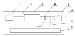
Fig. 1 is the structural representation of dedusting dehumidifier of the present invention.
The specific embodiment
Contrast accompanying drawing below; Through the description to embodiment, the effect of mutual alignment between the shape of specific embodiments of the invention such as related each member, structure, the each several part and annexation, each several part and operation principle etc. are done further to specify.
Embodiment 1:
As shown in Figure 1; The heat exchanger 4 that the dedusting dehumidifier of present embodiment comprises casing 3 with air suction inlet 1 and air outlet 2, is made up of evaporimeter and condenser; The tank 5 that the condensed water that the surface that results from evaporimeter is fallen is stored, air suction inlet 1 communicates through pipeline 6 with air outlet 2, and pipeline 6 is provided with filter screen 7 in tank 5 top positions; The top of filter screen 7 is provided with outlet pipe 8, and tank 5 communicates with outlet pipe 8 through water pump 9.
In dehumidification process; Dust from air suction inlet 1 leaked-in air can be tackled by filter screen 7, and the condensed water of tank 5 accumulated can flow to outlet pipe 8 under the effect of water pump 9, and flows out from outlet pipe 8; Flow down along filter screen 7; Dust on the filter screen 7 is taken away, finally dropped onto in the tank 5, thereby carry out air cleaning when realizing air dewetting.
Claims (2)
1. dedusting dehumidifier; The heat exchanger that it is characterized in that comprising casing, constitutes by evaporimeter and condenser with air suction inlet and air outlet; To the surface that results from evaporimeter and the tank that the condensed water that falls is stored, air suction inlet and air outlet communicate through pipeline, and the pipeline between said air suction inlet and the air outlet is provided with filter screen in the tank top position; The top of said filter screen is provided with outlet pipe, and said tank communicates with outlet pipe through water pump.
2. dedusting dehumidifier according to claim 1 is characterized in that the top of said filter screen is provided with a plurality of mozzles that are radial arrangement, and an end of said mozzle communicates with outlet pipe, and the other end links to each other with the top of filter screen.
Priority Applications (1)
| Application Number | Priority Date | Filing Date | Title |
|---|---|---|---|
| CN 201210280236 CN102818316A (en) | 2012-08-08 | 2012-08-08 | Dust removal dehumidifier |
Applications Claiming Priority (1)
| Application Number | Priority Date | Filing Date | Title |
|---|---|---|---|
| CN 201210280236 CN102818316A (en) | 2012-08-08 | 2012-08-08 | Dust removal dehumidifier |
Publications (1)
| Publication Number | Publication Date |
|---|---|
| CN102818316A true CN102818316A (en) | 2012-12-12 |
Family
ID=47302597
Family Applications (1)
| Application Number | Title | Priority Date | Filing Date |
|---|---|---|---|
| CN 201210280236 Pending CN102818316A (en) | 2012-08-08 | 2012-08-08 | Dust removal dehumidifier |
Country Status (1)
| Country | Link |
|---|---|
| CN (1) | CN102818316A (en) |
Cited By (6)
| Publication number | Priority date | Publication date | Assignee | Title |
|---|---|---|---|---|
| CN103267318A (en) * | 2013-05-10 | 2013-08-28 | 南京师范大学 | Triple-effect energy-saving gas washing and purification system and method |
| CN109028336A (en) * | 2018-07-17 | 2018-12-18 | 李成锦 | A kind of air dehumidifier |
| CN110822613A (en) * | 2018-08-13 | 2020-02-21 | 南通诺亚居环保科技有限公司 | A new air system for dehumidification, heat preservation and heat exchange for bathroom and its working method |
| CN113323845A (en) * | 2021-05-31 | 2021-08-31 | 江苏气老板节能技术有限公司 | Air compressor machine cooling dehumidification economizer that admits air |
| CN119146497A (en) * | 2024-11-18 | 2024-12-17 | 绿诺科技有限公司 | Heat abstractor of carbon dioxide heat pump air conditioner |
| CN120845831A (en) * | 2025-09-19 | 2025-10-28 | 格瑞海思人居环境科技(江苏)有限公司 | A dual-mode dehumidification air conditioning unit |
-
2012
- 2012-08-08 CN CN 201210280236 patent/CN102818316A/en active Pending
Cited By (7)
| Publication number | Priority date | Publication date | Assignee | Title |
|---|---|---|---|---|
| CN103267318A (en) * | 2013-05-10 | 2013-08-28 | 南京师范大学 | Triple-effect energy-saving gas washing and purification system and method |
| CN109028336A (en) * | 2018-07-17 | 2018-12-18 | 李成锦 | A kind of air dehumidifier |
| CN110822613A (en) * | 2018-08-13 | 2020-02-21 | 南通诺亚居环保科技有限公司 | A new air system for dehumidification, heat preservation and heat exchange for bathroom and its working method |
| CN113323845A (en) * | 2021-05-31 | 2021-08-31 | 江苏气老板节能技术有限公司 | Air compressor machine cooling dehumidification economizer that admits air |
| CN119146497A (en) * | 2024-11-18 | 2024-12-17 | 绿诺科技有限公司 | Heat abstractor of carbon dioxide heat pump air conditioner |
| CN119146497B (en) * | 2024-11-18 | 2025-02-18 | 绿诺科技有限公司 | A heat dissipation device for a carbon dioxide heat pump air conditioner |
| CN120845831A (en) * | 2025-09-19 | 2025-10-28 | 格瑞海思人居环境科技(江苏)有限公司 | A dual-mode dehumidification air conditioning unit |
Similar Documents
| Publication | Publication Date | Title |
|---|---|---|
| CN203744409U (en) | Water-column-shaped waterfall type indoor air filtering machine | |
| CN104266270A (en) | Air purifier and purifying method thereof | |
| CN201988277U (en) | Drainage plate and filter device using the same | |
| WO2014091087A1 (en) | An arrangement for cleaning of an exhaust air ductwork and a movable dust separation unit for cleaning of an exhaust air ductwork | |
| JP3156483U7 (en) | ||
| CN202719707U (en) | Dust-removing humidifier | |
| CN102865640B (en) | Clean room | |
| CN202734080U (en) | Machine capable of removing dust and moisture | |
| JP6506546B2 (en) | Gas turbine intake filter device | |
| CN201632176U (en) | Dry high efficiency dust collector | |
| CN203803300U (en) | Air purification device | |
| CN204227563U (en) | Air purifier | |
| CN202460385U (en) | Water-washing air purifier | |
| CN205825274U (en) | Multistage purification high-efficiency dehumidifier | |
| CN207654887U (en) | A kind of steelshop suction type fume dust remover | |
| CN206444360U (en) | A kind of oil removal filter | |
| CN205867884U (en) | Industrial dust filter unit | |
| CN203183843U (en) | Workshop smoke dust self-circulation purification treatment device | |
| CN102818328A (en) | Dust removing humidifier | |
| CN203663584U (en) | Oil fume and mist purifying equipment with high air volume | |
| CN102125409A (en) | Collection device and dust collector with same | |
| CN102679475A (en) | Indoor air purification system | |
| KR20180002695U (en) | Air filtering device for factory | |
| CN208771013U (en) | A pulse backflushing dust collector with uniform airflow distribution | |
| CN1296118C (en) | Vortex type gas filter |
Legal Events
| Date | Code | Title | Description |
|---|---|---|---|
| C06 | Publication | ||
| PB01 | Publication | ||
| C02 | Deemed withdrawal of patent application after publication (patent law 2001) | ||
| WD01 | Invention patent application deemed withdrawn after publication |
Application publication date: 20121212 |