CN102811587A - Communication machine cabinet for accommodating electronic elements - Google Patents

Communication machine cabinet for accommodating electronic elements Download PDF

Info

Publication number
CN102811587A
CN102811587A CN2012102678176A CN201210267817A CN102811587A CN 102811587 A CN102811587 A CN 102811587A CN 2012102678176 A CN2012102678176 A CN 2012102678176A CN 201210267817 A CN201210267817 A CN 201210267817A CN 102811587 A CN102811587 A CN 102811587A
Authority
CN
China
Prior art keywords
electronic component
communication cabinet
crossbeam
lead frame
component according
Prior art date
Legal status (The legal status is an assumption and is not a legal conclusion. Google has not performed a legal analysis and makes no representation as to the accuracy of the status listed.)
Pending
Application number
CN2012102678176A
Other languages
Chinese (zh)
Inventor
丁志永
Current Assignee (The listed assignees may be inaccurate. Google has not performed a legal analysis and makes no representation or warranty as to the accuracy of the list.)
SUZHOU A-RACK ENCLOSURE SYSTEMS Co Ltd
Original Assignee
SUZHOU A-RACK ENCLOSURE SYSTEMS Co Ltd
Priority date (The priority date is an assumption and is not a legal conclusion. Google has not performed a legal analysis and makes no representation as to the accuracy of the date listed.)
Filing date
Publication date
Application filed by SUZHOU A-RACK ENCLOSURE SYSTEMS Co Ltd filed Critical SUZHOU A-RACK ENCLOSURE SYSTEMS Co Ltd
Priority to CN2012102678176A priority Critical patent/CN102811587A/en
Publication of CN102811587A publication Critical patent/CN102811587A/en
Pending legal-status Critical Current

Links

Images

Landscapes

  • Casings For Electric Apparatus (AREA)

Abstract

The invention discloses a communication machine cabinet for accommodating electronic elements. The cabinet comprises two welding frames and at least two pairs of connecting cross beams, wherein the welding frames are arranged correspondingly; the connecting cross beams are arranged between the welding frames; connecting pieces are respectively fixed at the two ends of the connecting cross beams; the connecting cross beams are fixedly connected with the welding frames through the connecting piece; installing plates are fixed on the connecting cross beams; at least two pairs of installing brackets and wiring brackets which can slide along the installing plates are covered on the installing plates; a plurality of positioning holes are arranged at the bottom of the installing plate uniformly; and the positioning holes are arranged corresponding to round holes on the installing brackets and the wiring brackets. The communication machine cabinet for accommodating electronic elements is firm in structure; members are connected reliably and stably with good flexibility, frames are convenient to install and dismantle, the cabinet can be installed and transported conveniently by workers, the injury caused by collision or the damage during the transportation is prevented, thereby saving a great deal of time and labor.

Description

Be used to accommodate the communication cabinet of electronic component
Technical field
The present invention relates to electronic applications, particularly relate to a kind of communication cabinet that is used to accommodate electronic component.
Background technology
The high speed development that Along with computer technology is maked rapid progress, the extensive use of computer network has been deep into each corner of people's daily life.And be the supporting computer network rack market of computer network; The enclosure product that most of manufacturer provided all is the integral solder rack; Manufacturer carries out integrated welding with each parts of whole rack; Manufacture a rack integral body, integral body offers the computer network user then.The flexibility of this rack is relatively poor, and cost of transportation is also than higher, damages or damages if run in transit, must scrap by complete machine.
Summary of the invention
The technical problem that the present invention mainly solves provide a kind of good stability, flexibility good, be connected firmly, the communication cabinet that is used to accommodate electronic component of easy installation and removal.
For solving the problems of the technologies described above; The technical scheme that the present invention adopts is: a kind of communication cabinet that is used to accommodate electronic component is provided, comprises two corresponding lead frame that are provided with and at least two pairs of connection crossbeams, said connection crossbeam is arranged between the lead frame; Said connection crossbeam two ends are fixed with connector respectively; Connect crossbeam and be fixedly connected with lead frame through connector, be fixed with mounting panel on the said connection crossbeam, being coated with at least two pairs on the said mounting panel can be along the mounting bracket and the chute of mounting panel slip; Mounting panel bottom evenly offers some location holes, said location hole and the corresponding setting of circular hole on mounting bracket and the chute.
In preferred embodiment of the present invention, said connector is " П " type, connector be connected the crossbeam clamping.
In preferred embodiment of the present invention, be connected through some screw between said connector and the lead frame.
In preferred embodiment of the present invention, evenly offer some installing holes on the said mounting panel, said mounting bracket and chute are fixedly connected with installing hole through screw.
In preferred embodiment of the present invention, the rectangular and triangle of said location hole, rectangle location hole and triangle location hole are provided with at interval.
In preferred embodiment of the present invention, said mounting bracket and chute through hook plate be connected crossbeam and be slidingly connected.
In preferred embodiment of the present invention, further comprise top cover, said top cover both sides are respectively arranged with latch, and said latch is connected with lead frame respectively.
In preferred embodiment of the present invention, further comprise side door, said side door is connected with lead frame through hinge.
In preferred embodiment of the present invention, further comprise side cover, said side cover is arranged on and connects between the crossbeam, and the side cover lower end is " ㄣ " type, and is connected crossbeam and is connected.
In preferred embodiment of the present invention, further comprise castor, said castor is arranged on the lead frame bottom.
The invention has the beneficial effects as follows: the present invention is used to accommodate the communication cabinet sound construction of electronic component; Connect reliable, stable between each parts; Flexibility is good, and each framework easy installation and removal has made things convenient for workman's installation and carrying; Avoided running in the transportation and damaged or damage, saved great amount of time and labour.
Description of drawings
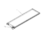
Fig. 1 is the perspective view that the present invention is used to accommodate communication cabinet one preferred embodiment of electronic component;
Fig. 2 is that the present invention is used to accommodate the structural representation that the connection crossbeam of the communication cabinet of electronic component is connected with lead frame;
Fig. 3 is the local enlarged diagram of I part among Fig. 2;
Fig. 4 is mounting bracket, the chute of the present invention's communication cabinet of being used to accommodate electronic component and is connected the structural representation that crossbeam connects;
Fig. 5 is the local enlarged diagram of II part among Fig. 4;
Fig. 6 is that the present invention is used to accommodate the structural representation that the side door of the communication cabinet of electronic component is connected with lead frame;
Fig. 7 is the local enlarged diagram of III part among Fig. 6;
Fig. 8 is that the present invention is used to accommodate the structural representation that the castor of the communication cabinet of electronic component is connected with lead frame;
The mark of each parts is following in the accompanying drawing: 1, lead frame, 2, connect crossbeam, 3, side door, 4, side cover, 5, top cover; 6, mounting bracket, 7, chute, 8, connector, 9, hinge, 10, mounting panel; 11, installing hole, 12, circular hole, 13, location hole, 14, castor.
 
Embodiment
Below in conjunction with accompanying drawing preferred embodiment of the present invention is set forth in detail, thereby protection scope of the present invention is made more explicit defining so that advantage of the present invention and characteristic can be easier to it will be appreciated by those skilled in the art that.
See also Fig. 1 to Fig. 5, the embodiment of the invention comprises:
A kind of communication cabinet that is used to accommodate electronic component; Comprise two corresponding lead frame that are provided with 1 and at least two pairs of connection crossbeams 2; Said connection crossbeam 2 is arranged between the lead frame 1, and said connection crossbeam 2 two ends are fixed with connector 8 respectively, connects crossbeam 2 and is fixedly connected with lead frame 1 through connector 8; Be fixed with mounting panel 10 on the said connection crossbeam 2; Be coated with at least two pairs of mounting bracket 6 and chutes 7 that can slide along mounting panel 10 on the said mounting panel 10, mounting panel 10 bottoms evenly offer some location holes 13, the circular hole 12 corresponding settings on said location hole 13 and mounting bracket 6 and the chute 7.
Said connection crossbeam 2 is three pairs, evenly is arranged between the lead frame 1, makes this rack more stable.
Like Fig. 2, shown in Figure 3, said connector 8 is " П " type, connector 8 be connected crossbeam 2 clampings, be connected through some screw between said connector 8 and the lead frame 1, this structure connects robust, easy installation and removal.
Like Fig. 4, shown in Figure 5; Said mounting bracket 6 and chute 7 through hook plate be connected crossbeam 2 and be slidingly connected; Evenly offer some installing holes 11 on the said mounting panel 10; Said mounting bracket 6 and chute 7 are fixedly connected with installing hole 11 through screw, and mounting bracket 6 and chute 7 can connect any sliding position on the crossbeam 2.
Said location hole 13 rectangular and triangles; Rectangle location hole and triangle location hole are provided with at interval; When location hole 13 punctual with 12 pairs of circular holes on mounting bracket 6, the chute 7; Mounting bracket 6, chute 7 accurate positioning then are described, promptly can mounting bracket 6, chute 7 be fixed on the mounting panel 10.
The present invention further comprises top cover 5, and said top cover 5 both sides are respectively arranged with latch, and said latch is connected with lead frame 1 respectively.The present invention further comprises side cover 4, and said side cover 4 is arranged on and connects between the crossbeam 2, and side cover 4 lower ends are " ㄣ " type, and is connected crossbeam 2 and is connected.Like Fig. 6, shown in Figure 7, the present invention further comprises side door 3, and said side door 3 is connected with lead frame 1 through hinge 9.The design of top cover 5, side door 3 and side cover 4 can let the staff watch the situation in the rack, in rack, takes out electronic equipment easily.
As shown in Figure 8, the present invention further comprises castor 14, and said castor 14 is arranged on lead frame 1 bottom, makes this rack convenient in carrying.
Compared with prior art; The present invention is used to accommodate the communication cabinet sound construction of electronic component, connects between each parts reliably, stablizes, and flexibility is good; Each framework easy installation and removal; Make things convenient for workman's installation and carrying, avoided running in the transportation and damaged or damage, saved great amount of time and labour.
The above is merely embodiments of the invention; Be not so limit claim of the present invention; Every equivalent structure or equivalent flow process conversion that utilizes specification of the present invention and accompanying drawing content to be done; Or directly or indirectly be used in other relevant technical fields, all in like manner be included in the scope of patent protection of the present invention.

Claims (10)

1. communication cabinet that is used to accommodate electronic component; Comprise two corresponding lead frame (1) that are provided with and at least two pairs of connection crossbeams (2); Said connection crossbeam (2) is arranged between the lead frame (1); It is characterized in that: said connection crossbeam (2) two ends are fixed with connector (8) respectively; Connect crossbeam (2) and be fixedly connected with lead frame (1) through connector (8), be fixed with mounting panel (10) on the said connection crossbeam (2), being coated with at least two pairs on the said mounting panel (10) can be along the mounting bracket (6) and the chute (7) of mounting panel (10) slip; Mounting panel (10) bottom evenly offers some location holes (13), the corresponding setting of circular hole (12) on said location hole (13) and mounting bracket (6) and the chute (7).
2. the communication cabinet that is used to accommodate electronic component according to claim 1 is characterized in that: said connector (8) is " П " type, connector (8) be connected crossbeam (2) clamping.
3. the communication cabinet that is used to accommodate electronic component according to claim 1 is characterized in that: be connected through some screw between said connector (8) and the lead frame (1).
4. the communication cabinet that is used to accommodate electronic component according to claim 1; It is characterized in that: evenly offer some installing holes (11) on the said mounting panel (10), said mounting bracket (6) and chute (7) are fixedly connected with installing hole (11) through screw.
5. the communication cabinet that is used to accommodate electronic component according to claim 1 is characterized in that: the rectangular and triangle of said location hole (13), rectangle location hole and triangle location hole are provided with at interval.
6. the communication cabinet that is used to accommodate electronic component according to claim 1 is characterized in that: said mounting bracket (6) and chute (7) through hook plate be connected crossbeam (2) and be slidingly connected.
7. the communication cabinet that is used to accommodate electronic component according to claim 1 is characterized in that: further comprise top cover (5), said top cover (5) both sides are respectively arranged with latch, and said latch is connected with lead frame (1) respectively.
8. the communication cabinet that is used to accommodate electronic component according to claim 1 is characterized in that: further comprise side door (3), said side door (3) is connected with lead frame (1) through hinge (9).
9. the communication cabinet that is used to accommodate electronic component according to claim 1; It is characterized in that: further comprise side cover (4); Said side cover (4) is arranged on and connects between the crossbeam (2), and side cover (4) lower end is " ㄣ " type, and is connected crossbeam (2) and is connected.
10. the communication cabinet that is used to accommodate electronic component according to claim 1 is characterized in that: further comprise castor (14), said castor (14) is arranged on lead frame (1) bottom.
CN2012102678176A 2012-07-31 2012-07-31 Communication machine cabinet for accommodating electronic elements Pending CN102811587A (en)

Priority Applications (1)

Application Number Priority Date Filing Date Title
CN2012102678176A CN102811587A (en) 2012-07-31 2012-07-31 Communication machine cabinet for accommodating electronic elements

Applications Claiming Priority (1)

Application Number Priority Date Filing Date Title
CN2012102678176A CN102811587A (en) 2012-07-31 2012-07-31 Communication machine cabinet for accommodating electronic elements

Publications (1)

Publication Number Publication Date
CN102811587A true CN102811587A (en) 2012-12-05

Family

ID=47235126

Family Applications (1)

Application Number Title Priority Date Filing Date
CN2012102678176A Pending CN102811587A (en) 2012-07-31 2012-07-31 Communication machine cabinet for accommodating electronic elements

Country Status (1)

Country Link
CN (1) CN102811587A (en)

Cited By (2)

* Cited by examiner, † Cited by third party
Publication number Priority date Publication date Assignee Title
CN104955288A (en) * 2014-03-28 2015-09-30 苏州安瑞可机柜系统有限公司 Splicing-type communication cabinet
CN105283027A (en) * 2014-07-24 2016-01-27 苏州安瑞可机柜系统有限公司 Quickly-installed cabinet frame body

Citations (4)

* Cited by examiner, † Cited by third party
Publication number Priority date Publication date Assignee Title
CN201690691U (en) * 2010-05-06 2010-12-29 上海新朋金属制品有限公司 Assembling type network cabinet
CN201766793U (en) * 2010-08-09 2011-03-16 中兴通讯股份有限公司 General stand for machine cabinet
CN102548288A (en) * 2011-12-14 2012-07-04 李华 Cabinet for accommodating electric element
CN202841785U (en) * 2012-07-31 2013-03-27 苏州美露机柜系统有限公司 Communication cabinet for accommodating electronic component

Patent Citations (4)

* Cited by examiner, † Cited by third party
Publication number Priority date Publication date Assignee Title
CN201690691U (en) * 2010-05-06 2010-12-29 上海新朋金属制品有限公司 Assembling type network cabinet
CN201766793U (en) * 2010-08-09 2011-03-16 中兴通讯股份有限公司 General stand for machine cabinet
CN102548288A (en) * 2011-12-14 2012-07-04 李华 Cabinet for accommodating electric element
CN202841785U (en) * 2012-07-31 2013-03-27 苏州美露机柜系统有限公司 Communication cabinet for accommodating electronic component

Cited By (2)

* Cited by examiner, † Cited by third party
Publication number Priority date Publication date Assignee Title
CN104955288A (en) * 2014-03-28 2015-09-30 苏州安瑞可机柜系统有限公司 Splicing-type communication cabinet
CN105283027A (en) * 2014-07-24 2016-01-27 苏州安瑞可机柜系统有限公司 Quickly-installed cabinet frame body

Similar Documents

Publication Publication Date Title
CN202958083U (en) Service cabinet
CN202708512U (en) Support with adjustable height
CN202958084U (en) Network cabinet
CN202197457U (en) Cabinet used for containing electronic elements
CN202488905U (en) Cabinet for accommodating electronic components
CN203491581U (en) Draw-out type switch cabinet interlocking device
CN201946654U (en) Detachable battery rack
CN202841785U (en) Communication cabinet for accommodating electronic component
CN106129819A (en) Device framework structure and use the prefabricated cabin frame of this structure
CN107626488B (en) Can dismantle and hide and spout tool
CN204948511U (en) A kind of fixture of docking for auxiliary pcb board
CN207070539U (en) Circuit board mounting structure and display
CN205407016U (en) Make simple and direct block terminal
CN201947570U (en) Installation piece
CN202857201U (en) Tray used for communication cabinet
CN203939253U (en) A kind of horizontal channel bracing frame for Construction of High-rise
CN104909272B (en) Modular cable discharges coaster and application method thereof
CN204517314U (en) A kind of trough type bridge frame
CN205950275U (en) A device for fixing the electrical box of a machine tool
CN203351960U (en) A universal capacitor installing board
CN204727474U (en) Modular cable discharges coaster
CN210725691U (en) Novel computer network rack
CN202799513U (en) An assembled rack
CN205385654U (en) Panel turnover machine activity track
CN204886663U (en) Inverter wheel module installation guide rail device

Legal Events

Date Code Title Description
C06 Publication
PB01 Publication
C10 Entry into substantive examination
SE01 Entry into force of request for substantive examination
DD01 Delivery of document by public notice

Addressee: Patent holder of Suzhou display cabinet system Co., Ltd.

Document name: Notification that Application Deemed not to be Proposed

C53 Correction of patent of invention or patent application
CB02 Change of applicant information

Address after: Wuzhong District Wuzhong Economic Development Zone Suzhou city Jiangsu province 215000 Yue Xi Youxiang Street Road No. 1

Applicant after: SUZHOU A-RACK ENCLOSURE SYSTEM CO., LTD.

Address before: Wuzhong District Wuzhong Economic Development Zone Suzhou city Jiangsu province 215000 Yue Xi Youxiang Street Road No. 1

Applicant before: SUZHOU A-RACK ENCLOSURE SYSTEMS CO., LTD.

COR Change of bibliographic data

Free format text: CORRECT: APPLICANT; FROM: SUZHOU MERO CABINET SYSTEM CO., LTD. TO: SUZHOU A-RACK ENCLOSURE SYSTEMS CO., LTD.

DD01 Delivery of document by public notice

Addressee: office

Document name: Notification that Application Deemed not to be Proposed

C53 Correction of patent of invention or patent application
CB02 Change of applicant information

Address after: 215000 No. 10 Ting Road, Suzhou hi tech Development Zone, Jiangsu, Suzhou

Applicant after: SUZHOU A-RACK ENCLOSURE SYSTEM CO., LTD.

Address before: Wuzhong District Wuzhong Economic Development Zone Suzhou city Jiangsu province 215000 Yue Xi Youxiang Street Road No. 1

Applicant before: SUZHOU A-RACK ENCLOSURE SYSTEMS CO., LTD.

COR Change of bibliographic data

Free format text: CORRECT: APPLICANT; FROM: SUZHOU MERO CABINET SYSTEM CO., LTD. TO: SUZHOU A-RACK ENCLOSURE SYSTEMS CO., LTD.

C12 Rejection of a patent application after its publication
RJ01 Rejection of invention patent application after publication

Application publication date: 20121205