CN102699178A - Top cropping mould for car decorative part with strip-shaped abnormal section - Google Patents
Top cropping mould for car decorative part with strip-shaped abnormal section Download PDFInfo
- Publication number
- CN102699178A CN102699178A CN2012101648559A CN201210164855A CN102699178A CN 102699178 A CN102699178 A CN 102699178A CN 2012101648559 A CN2012101648559 A CN 2012101648559A CN 201210164855 A CN201210164855 A CN 201210164855A CN 102699178 A CN102699178 A CN 102699178A
- Authority
- CN
- China
- Prior art keywords
- lower knife
- knife
- fixed
- spring
- movable
- Prior art date
- Legal status (The legal status is an assumption and is not a legal conclusion. Google has not performed a legal analysis and makes no representation as to the accuracy of the status listed.)
- Granted
Links
Images





Landscapes
- Details Of Cutting Devices (AREA)
- Manufacturing And Processing Devices For Dough (AREA)
Abstract
Description
技术领域 technical field
本发明涉及一种冲裁模具,尤其是一种适用于窄条状异型截面汽车装饰件切头的模具,属于金属冲压技术领域。 The invention relates to a blanking die, in particular to a die suitable for cutting the head of a narrow strip-shaped special-shaped cross-section automobile trim, and belongs to the technical field of metal stamping.
背景技术 Background technique
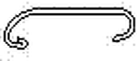
在汽车附件中,有一类截面呈“C”型(图1、图2所示)的长条形零件,如雨檐、饰条等。此类零件的生产过程是先辊压定型,然后经模具切头来确定零件的长度、形状。 Among the automotive accessories, there is a type of long strip parts with a "C" cross section (shown in Figure 1 and Figure 2), such as rain eaves and decorative strips. The production process of this kind of parts is first rolling and shaping, and then the length and shape of the parts are determined by cutting the head of the die.
目前,此类零件的切头加工通常采用固定切刀,上料时需要按产品的弧形将工件穿进下模,由于产品截面一般很窄,穿料费时费力;另外,该加工方式只能冲切零件的一个端头,需通过下道工序冲切另一个端头来确定零件的长度,为保证产品长度的精度要求就必须设置准确的定位机构,这又给调试、生产增加了难度,不仅工作效率低、生产周期长,还增加了模具及产品的制造成本。 At present, the head cutting process of such parts usually adopts a fixed cutter. When feeding, the workpiece needs to be inserted into the lower die according to the arc shape of the product. Since the cross section of the product is generally very narrow, it takes time and effort to thread the material; in addition, this processing method can only When punching one end of a part, the other end needs to be punched in the next process to determine the length of the part. In order to ensure the accuracy of the product length, an accurate positioning mechanism must be set, which adds difficulty to debugging and production. Not only the work efficiency is low, the production cycle is long, but also the manufacturing cost of molds and products is increased.
发明内容 Contents of the invention
本发明的目的在于针对现有技术之弊端,提供一种性能可靠、操作方便、可通过同时冲切两个端头的方法来确定零件长度、并能降低调试及生产的难度、提高生产效率、降低生产成本的窄条状异形截面汽车装饰件切头模具。 The object of the present invention is to aim at the drawbacks of the prior art, to provide a method with reliable performance, convenient operation, which can determine the length of the part by punching two ends at the same time, reduce the difficulty of debugging and production, and improve production efficiency. A cutting die for trimming automotive trim parts with narrow strips and special-shaped cross-sections to reduce production costs.
本发明所述问题是以下述技术方案实现的: Problem described in the present invention is realized with following technical scheme:
一种窄条状异形截面汽车装饰件切头模具,它包括结构相同、左右布置的两个切头模具单元及中间托料块,所述两个切头模具单元摆放角度与工件两端弧形匹配,两个切头模具单元摆放位置与工件长度尺寸匹配。 A trimming die for a narrow strip-shaped special-shaped cross-section automobile trim, which includes two trimming die units with the same structure and arranged left and right and a middle support block. Shape matching, the placement of the two cutting die units matches the length and size of the workpiece.
上述窄条状异形截面汽车装饰件切头模具,所述切头模具单元由上模部分和下模部分组成,所述上模部分包括上模板、上垫板、上刀座、上刀和弹性压料机构,所述上刀座、上垫板由螺纹连接机构依次固定于上模板上,上刀固定在上刀座上,所述弹性压料机构包括压料板、卸料螺钉和弹簧Ⅰ,所述压料板通过卸料螺钉与上刀座相连,所述弹簧Ⅰ穿过上垫板及上刀座,上端与上模板连接,下端与压料板连接。 The above-mentioned narrow-strip special-shaped cross-section automotive trim cutting die, the cutting die unit is composed of an upper die part and a lower die part, and the upper die part includes an upper template, an upper backing plate, an upper knife seat, an upper knife and an elastic The pressing mechanism, the upper knife seat and the upper backing plate are sequentially fixed on the upper template by the threaded connection mechanism, the upper knife is fixed on the upper knife seat, and the elastic pressing mechanism includes a pressing plate, a discharge screw and a spring I , the clamping plate is connected with the upper tool seat through the discharge screw, the spring I passes through the upper backing plate and the upper tool seat, the upper end is connected with the upper template, and the lower end is connected with the pressing plate.
上述窄条状异形截面汽车装饰件切头模具,所述切头模具单元的下模部分包括下模板、下垫板、下刀座、下刀、弹簧Ⅱ和浮料销,所述下刀座、下垫板采用螺纹连接依次固定于下模板上,所述下刀包括固定下刀和活动下刀,所述固定下刀由固定下刀Ⅰ、固定下刀Ⅱ、固定下刀Ⅲ组成,所述活动下刀由活动下刀Ⅰ和活动下刀Ⅱ组成,其中三个固定下刀固定在下刀座上,两个活动下刀分插在三个固定下刀之间,所述弹簧Ⅱ和浮料销均为对称布置结构,弹簧Ⅱ下端安装在下模板上,上端与浮料销连接,所述浮料销下端为阶梯结构,浮料销位于弹簧Ⅱ和活动下刀之间。 The above-mentioned narrow-strip special-shaped cross-section automotive trim cutting die, the lower die part of the cutting die unit includes a lower template, a lower backing plate, a lower knife seat, a lower knife, a spring II and a floating material pin, and the lower knife seat , The lower backing plate is sequentially fixed on the lower template by screw connection. The lower knife includes a fixed lower knife and a movable lower knife. The fixed lower knife is composed of a fixed lower knife I, a fixed lower knife II, and a fixed lower knife III. The movable lower knife is composed of movable lower knife I and movable lower knife II, among which three fixed lower knives are fixed on the lower knife seat, and two movable lower knives are respectively inserted between the three fixed lower knives. The spring II and the floating The material pins are arranged in a symmetrical structure. The lower end of the spring II is installed on the lower template, and the upper end is connected with the floating material pin. The lower end of the floating material pin is a stepped structure, and the floating material pin is located between the spring II and the movable lower knife.
上述窄条状异形截面汽车装饰件切头模具,所述活动下刀Ⅰ、活动下刀Ⅱ与固定下刀Ⅰ的接触面为斜面,其中固定下刀Ⅰ左侧斜面与固定下刀Ⅰ右侧斜面之间夹角α=8~10°,在固定下刀Ⅰ的两侧斜面上均设有燕尾导向槽,在活动下刀Ⅰ、活动下刀Ⅱ的斜面上设置导向滑块,所述固定下刀Ⅰ的燕尾导向槽与活动下刀Ⅰ、活动下刀Ⅱ的导向滑块配装。 In the above-mentioned narrow-strip special-shaped cross-section cutting head mold for automotive trim parts, the contact surfaces of the movable lower knife I, the movable lower knife II and the fixed lower knife I are inclined surfaces, wherein the inclined surface on the left side of the fixed lower knife I and the right side of the fixed lower knife I The angle between the slopes is α=8~10°. Dovetail guide grooves are provided on the slopes on both sides of the fixed lower knife I, and guide sliders are set on the slopes of the movable lower knife I and the movable lower knife II. The dovetail guide groove of the lower knife I is assembled with the guide sliders of the movable lower knife I and the movable lower knife II.
上述窄条状异形截面汽车装饰件切头模具,所述上模部分的弹簧Ⅰ为中载荷弹簧,所述下模部分的弹簧Ⅱ为轻小载荷弹簧。 In the head-cutting mold for automotive decorative parts with narrow strips and special-shaped cross-sections, the spring I of the upper mold part is a spring with a medium load, and the spring II of the lower mold part is a spring with a light and small load.
上述窄条状异形截面汽车装饰件切头模具,所述中间托料块工作型面与工件截面形状匹配。 In the head-cutting mold for the narrow strip-shaped special-shaped cross-section automotive trim, the working surface of the intermediate support block matches the cross-sectional shape of the workpiece.
本发明通过左右布置的两个切头模具单元实现了同时冲切两个端头的目的,去除了两次冲切所必须的定位机构,既确保了工件的加工精度,又简化了放料操作;在本发明结构中,活动下刀Ⅰ、活动下刀Ⅱ与固定下刀Ⅰ均设有相同角度的斜面,且固定下刀Ⅰ的两侧斜面角度内倾,夹角在8-10°之间,固定下刀Ⅰ及活动下刀Ⅰ、活动下刀Ⅱ还分别设有相互配合滑动的燕尾式导向机构,可使活动下刀在弹簧Ⅱ的弹力作用下向上、向内移动,从而使两活动下刀外侧边的横向距离随着刀具的移动而逐渐减小,直至小于产品截形内侧宽度,以此可实现从上向下直接放料的目的;在本发明结构中,上模部分的弹簧Ⅰ为中载荷弹簧,下模部分的弹簧Ⅱ为轻小载荷弹簧,故弹性压料机构弹簧的力量要比支撑活动下刀弹簧的力量大得多,这样就使得上模下行时先将活动下刀压下,在活动下刀与固定下刀结合并处于与产品截面形状一致的状态后,上下刀具配合完成工件端头的冲切动作。总之,本发明具有性能可靠、结构合理、操作方便的特点,不仅能显著提高生产效率和产品质量,而且能降低模具及产品的制造成本。 The invention realizes the purpose of punching two ends at the same time through the two cutting die units arranged on the left and right, and eliminates the positioning mechanism necessary for the two punching, which not only ensures the processing accuracy of the workpiece, but also simplifies the discharging operation ; In the structure of the present invention, the movable lower knife I, the movable lower knife II and the fixed lower knife I are all provided with inclined surfaces of the same angle, and the angles of the inclined surfaces on both sides of the fixed lower knife I are inwardly inclined, and the included angle is between 8-10° The fixed lower knife Ⅰ, the movable lower knife Ⅰ, and the movable lower knife Ⅱ are also provided with dovetail guide mechanisms that cooperate with each other and slide, so that the movable lower knife can move upward and inward under the elastic force of the spring Ⅱ, so that the two movable The lateral distance of the outer edge of the lower knife gradually decreases with the movement of the knife until it is less than the inner width of the sectional shape of the product, so that the purpose of direct discharging from top to bottom can be realized; in the structure of the present invention, the upper mold part Spring Ⅰ is a medium-load spring, and spring Ⅱ of the lower die is a spring with light and small load. Therefore, the force of the spring of the elastic pressing mechanism is much greater than the force of the spring supporting the movable lower knife, so that the upper die will be moved first when it goes down. The lower knife is pressed down. After the movable lower knife is combined with the fixed lower knife and is in a state consistent with the cross-sectional shape of the product, the upper and lower knives cooperate to complete the punching action of the end of the workpiece. In a word, the present invention has the characteristics of reliable performance, reasonable structure and convenient operation, which can not only significantly improve production efficiency and product quality, but also reduce the manufacturing cost of molds and products.
附图说明 Description of drawings
下面结合附图对本发明作进一步说明。 The present invention will be further described below in conjunction with accompanying drawing.
图1、图2是适用于本发明的工件截面图; Fig. 1, Fig. 2 are workpiece cross-sectional views applicable to the present invention;
图3是本发明的结构图; Fig. 3 is a structural diagram of the present invention;
图4是切头模具单元结构示意图; Fig. 4 is a structural schematic diagram of a cutting die unit;
图5是模具闭合状态上下刀位置示意图; Fig. 5 is a schematic diagram of the position of the upper and lower cutters in the closed state of the mold;
图6是固定下刀Ⅰ结构示意图; Fig. 6 is a schematic diagram of the structure of the fixed lower knife I;
图7是活动下刀Ⅰ、活动下刀Ⅱ结构示意图; Fig. 7 is a schematic diagram of the structure of movable lower knife I and movable lower knife II;
图8是模具开模状态示意图; Fig. 8 is a schematic diagram of the mold opening state;
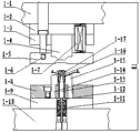
图9是模具上模下行状态示意图; Fig. 9 is a schematic diagram of the downward movement state of the mold upper mold;
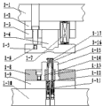
图10是模具闭合状态示意图。 Fig. 10 is a schematic diagram of the closed state of the mold.
图中各标号为:1、切头模具单元,1-1、上模板,1-2、上垫板,1-3、上刀座,1-4、上刀,1-5、压料板,1-6、卸料螺钉,1-7、弹簧Ⅰ,1-8、下刀座,1-9、下垫板,1-10、下模板,1-11、弹簧Ⅱ,1-12、浮料销,1-13、固定下刀Ⅰ,1-14、固定下刀Ⅱ,1-15、固定下刀Ⅲ,1-16、活动下刀Ⅰ,1-17、活动下刀Ⅱ,2、中间托料块,3、工件; Each label in the figure is: 1, head cutting die unit, 1-1, upper template, 1-2, upper backing plate, 1-3, upper knife seat, 1-4, upper knife, 1-5, pressure plate , 1-6, unloading screw, 1-7, spring Ⅰ, 1-8, lower knife seat, 1-9, lower backing plate, 1-10, lower template, 1-11, spring Ⅱ, 1-12, Floating material pin, 1-13, fixed lower knife Ⅰ, 1-14, fixed lower knife Ⅱ, 1-15, fixed lower knife Ⅲ, 1-16, movable lower knife Ⅰ, 1-17, movable lower knife Ⅱ, 2 , the middle support block, 3, the workpiece;
a、固定下刀Ⅰ左侧斜面,b、固定下刀Ⅰ右侧斜面,a’、活动下刀Ⅰ的斜面,b’、活动下刀Ⅱ的斜面。 a. The left inclined surface of the fixed lower knife I, b. The right inclined surface of the fixed lower knife I, a', the inclined surface of the movable lower knife I, b', the inclined surface of the movable lower knife II.
具体实施方式 Detailed ways
参看图 3,本发明包括结构相同、左右布置的两个切头模具单元1及中间托料块2,所述两个切头模具单元1摆放角度与工件3两端的弧形匹配,两个切头模具单元1摆放位置与工件3的长度尺寸匹配。
Referring to Fig. 3, the present invention comprises two head-cutting die units 1 and an
参看图3、图4,本发明的切头模具单元1由上模部分和下模部分组成,所述上模部分包括上模板1-1、上垫板1-2、上刀座1-3、上刀1-4和弹性压料机构,所述上刀座1-3、上垫板1-2采用螺纹连接依次固定于上模板1-1上,上刀1-4固定在上刀座1-3上,所述弹性压料机构包括压料板1-5、卸料螺钉1-6和弹簧Ⅰ1-7,所述压料板1-5通过卸料螺钉1-6与上刀座1-3相连,所述弹簧Ⅰ1-7穿过上垫板1-2及上刀座1-3,上端与上模板1-1连接,下端与压料板1-5连接。 Referring to Fig. 3 and Fig. 4, the head cutting die unit 1 of the present invention is composed of an upper die part and a lower die part, and the upper die part includes an upper template 1-1, an upper backing plate 1-2, and an upper knife seat 1-3 , the upper knife 1-4 and the elastic pressing mechanism, the upper knife seat 1-3 and the upper backing plate 1-2 are fixed on the upper template 1-1 in turn by screw connection, and the upper knife 1-4 is fixed on the upper knife seat 1-3, the elastic pressing mechanism includes a pressing plate 1-5, a discharge screw 1-6 and a spring I1-7, and the pressing plate 1-5 connects with the upper knife seat through the discharging screw 1-6 1-3 are connected, the spring I1-7 passes through the upper backing plate 1-2 and the upper knife seat 1-3, the upper end is connected with the upper template 1-1, and the lower end is connected with the pressure plate 1-5.
参看图3、图4,本发明切头模具单元的下模部分包括下模板1-10、下垫板1-9、下刀座1-8、下刀、弹簧Ⅱ1-11和浮料销1-12,所述下刀座1-8、下垫板1-9采用螺纹连接依次固定于下模板1-10上,所述下刀包括固定下刀和活动下刀,所述固定下刀由固定下刀Ⅰ1-13、固定下刀Ⅱ1-14、固定下刀Ⅲ1-15组成,所述活动下刀由活动下刀Ⅰ1-16和活动下刀Ⅱ1-17组成,其中三个固定下刀固定在下刀座1-8上,两个活动下刀分插在三个固定下刀之间,所述弹簧Ⅱ1-11和浮料销1-12均为对称布置结构,弹簧Ⅱ1-11下端安装在下模板1-10上,上端与浮料销1-12连接,所述浮料销1-12下端为阶梯结构,浮料销1-12位于弹簧Ⅱ1-11和活动下刀之间。 Referring to Fig. 3 and Fig. 4, the lower mold part of the head cutting die unit of the present invention includes a lower template 1-10, a lower backing plate 1-9, a lower knife seat 1-8, a lower knife, a spring II 1-11 and a floating material pin 1 -12, the lower knife seat 1-8 and the lower backing plate 1-9 are sequentially fixed on the lower template 1-10 by screw connection, the lower knife includes a fixed lower knife and a movable lower knife, and the fixed lower knife is composed of Fixed lower knife I1-13, fixed lower knife II1-14, fixed lower knife III1-15, the movable lower knife is composed of movable lower knife I1-16 and movable lower knife II1-17, three of which are fixed On the lower knife seat 1-8, two movable lower knives are inserted between three fixed lower knives, the spring II1-11 and the floating material pin 1-12 are symmetrically arranged, and the lower end of the spring II1-11 is installed on the lower On the template 1-10, the upper end is connected with the floating material pin 1-12, the lower end of the floating material pin 1-12 is a stepped structure, and the floating material pin 1-12 is located between the spring II 1-11 and the movable lower knife.
参看图4、图6、图7,本发明的活动下刀Ⅰ1-16、活动下刀Ⅱ1-17与固定下刀Ⅰ1-13的接触面为斜面,其中固定下刀Ⅰ左侧斜面a与固定下刀Ⅰ右侧斜面b之间夹角α=8~10°,在固定下刀Ⅰ1-13的两侧斜面上均设有燕尾导向槽,在活动下刀Ⅰ的斜面a’、活动下刀Ⅱ的斜面b’上设置导向滑块,所述固定下刀Ⅰ1-13的燕尾导向槽与活动下刀Ⅰ1-16、活动下刀Ⅱ1-17的导向滑块配装。 Referring to Fig. 4, Fig. 6, Fig. 7, the contact surfaces of the movable lower knife I1-16, the movable lower knife II1-17 and the fixed lower knife I1-13 of the present invention are inclined planes, wherein the left slope a of the fixed lower knife I and the fixed The included angle between the slope b on the right side of the lower knife I is α=8~10°. There are dovetail guide grooves on the slopes on both sides of the fixed lower knife I1-13. A guide slider is set on the slope b' of II, and the dovetail guide groove of the fixed lower knife I1-13 is fitted with the guide sliders of the movable lower knife I1-16 and the movable lower knife II1-17.
参看图4,本发明的上模部分的弹簧Ⅰ1-7为中载荷弹簧,所述下模部分的弹簧Ⅱ1-11为轻小载荷弹簧。 Referring to Fig. 4, the springs I1-7 of the upper die part of the present invention are medium-load springs, and the springs II1-11 of the lower die part are light and small-load springs.
参看图3,本发明的中间托料块2工作型面与工件3的截面形状匹配。
Referring to FIG. 3 , the working surface of the
参看图8、图9、图10,并结合具体实施例对本发明的工作过程进行描述: With reference to Fig. 8, Fig. 9, Fig. 10, and in conjunction with specific embodiment the course of work of the present invention is described:
图8为一种窄条状“C”型截面汽车装饰件切头模具的切头模具单元1开模状态示意图,此时上模抬起,上模板1-1与下模板1-10之间距离H1=240mm, 活动下刀Ⅰ1-16、活动下刀Ⅱ1-17被弹簧Ⅱ 1-11抬起7mm的高度,活动下刀1-16、1-17两侧边的横向距离小于工件3的截面内空宽度。将待加工的工件从上向下放在模具下刀上,工件3的中部由中间托料块2托住,注意目视工件3的两端头均伸出模具下刀边缘。
Fig. 8 is a schematic diagram of the mold opening state of the cutting die unit 1 of a narrow "C"-shaped cross-section cutting die for automobile trim parts. Distance H1=240mm, movable lower knife Ⅰ 1-16, movable lower knife Ⅱ 1-17 are lifted by spring Ⅱ 1-11 to a height of 7mm, and the lateral distance between the two sides of movable lower knife 1-16, 1-17 is less than that of workpiece 3 Section inner void width. Put the workpiece to be processed on the lower knife of the mold from top to bottom, the middle part of the workpiece 3 is supported by the
图9所示为机床上滑块带动上模板1-1下行至压料板1-5与工件接触时的结构状态,活动下刀1-16、1-17开始在压料板1-5的推力作用下下行,同时压料板1-5相对于上刀座1-3向上运动,但压料板1-5上行的速度远小于活动下刀的下行速度,直到活动下刀下行到底,并与固定下刀1-13结合,顶面形状与工件截面形态一致后,此时上模板1-1与下模板1-10之间距离H2=215mm,上刀1-4仍未接触到工件3,本实施例中活动下刀下行7mm,压料板上行3mm。 Figure 9 shows the structural state when the upper slide block of the machine tool drives the upper template 1-1 down to the pressure plate 1-5 when it contacts the workpiece. Under the action of the thrust, the pressing plate 1-5 moves upward relative to the upper knife seat 1-3, but the upward speed of the pressing plate 1-5 is much lower than the downward speed of the movable lower knife, until the movable lower knife goes down to the end, and Combined with the fixed lower knife 1-13, after the shape of the top surface is consistent with the cross-sectional shape of the workpiece, the distance between the upper template 1-1 and the lower template 1-10 is H2=215mm, and the upper knife 1-4 has not yet touched the workpiece 3 , In the present embodiment, the movable lower knife moves downward by 7mm, and the pressing plate moves upward by 3mm.
然后上模继续下行,下刀状态不变,压料板1-5上行,上刀1-4凸出压料板1-5下边缘,开始冲切工件3,直到机床到达下死点工件端头被切断,此时状态如图10所示,上模板1-1与下模板1-10之间距离H3=207mm。最后,机床上滑块回程,上模上行,压料板1-5离开零件,弹簧Ⅱ 1-11将活动下刀抬起,活动下刀两侧边横向距离又小于工件3的截面内空宽度,机床停止运行后,从下向上取出产品件,完成切头过程。 Then the upper mold continues to move downward, the state of the lower knife remains unchanged, the pressure plate 1-5 moves upward, the upper knife 1-4 protrudes from the lower edge of the pressure plate 1-5, and the workpiece 3 starts to be punched until the machine tool reaches the workpiece end at the bottom dead point The head is cut off, and the state is shown in Figure 10 at this time, the distance H3=207mm between the upper template 1-1 and the lower template 1-10. Finally, the upper slider of the machine tool returns, the upper mold moves upward, the pressing plate 1-5 leaves the part, the spring II 1-11 lifts the movable lower knife, and the lateral distance between the two sides of the movable lower knife is smaller than the cross-sectional inner width of the workpiece 3 , after the machine tool stops running, take out the product parts from the bottom up to complete the head cutting process.
Claims (6)
Priority Applications (1)
| Application Number | Priority Date | Filing Date | Title |
|---|---|---|---|
| CN201210164855.9A CN102699178B (en) | 2012-05-25 | 2012-05-25 | Top cropping mould for car decorative part with strip-shaped abnormal section |
Applications Claiming Priority (1)
| Application Number | Priority Date | Filing Date | Title |
|---|---|---|---|
| CN201210164855.9A CN102699178B (en) | 2012-05-25 | 2012-05-25 | Top cropping mould for car decorative part with strip-shaped abnormal section |
Publications (2)
| Publication Number | Publication Date |
|---|---|
| CN102699178A true CN102699178A (en) | 2012-10-03 |
| CN102699178B CN102699178B (en) | 2014-08-27 |
Family
ID=46892396
Family Applications (1)
| Application Number | Title | Priority Date | Filing Date |
|---|---|---|---|
| CN201210164855.9A Expired - Fee Related CN102699178B (en) | 2012-05-25 | 2012-05-25 | Top cropping mould for car decorative part with strip-shaped abnormal section |
Country Status (1)
| Country | Link |
|---|---|
| CN (1) | CN102699178B (en) |
Cited By (3)
| Publication number | Priority date | Publication date | Assignee | Title |
|---|---|---|---|---|
| CN103111509A (en) * | 2013-01-24 | 2013-05-22 | 宁波福耀汽车零部件有限公司 | One-time punching device adjustable in three dimensions of vehicle window frame strip |
| CN109877214A (en) * | 2019-03-22 | 2019-06-14 | 厦门金龙汽车车身有限公司 | A kind of material drag component and its waste material with the component utilize mechanism |
| CN113600671A (en) * | 2021-08-30 | 2021-11-05 | 秦皇岛方华埃西姆机械有限公司 | Die-cut frock of aluminium alloy trim side stud |
Citations (5)
| Publication number | Priority date | Publication date | Assignee | Title |
|---|---|---|---|---|
| JPH08323428A (en) * | 1995-05-31 | 1996-12-10 | Nissan Motor Co Ltd | Stamping die and stamping method |
| JP2003230919A (en) * | 2002-02-14 | 2003-08-19 | Japan Aviation Electronics Industry Ltd | Press mold equipment |
| CN101767143A (en) * | 2009-12-31 | 2010-07-07 | 王瑞峰 | One-off edge cutting device |
| CN201791815U (en) * | 2010-09-30 | 2011-04-13 | 鑫鸿交通工业(安徽)有限公司 | Shearing die for metal plate of automobile |
| CN202129336U (en) * | 2011-06-20 | 2012-02-01 | 宁波福耀汽车零部件有限公司 | Top crop die |
-
2012
- 2012-05-25 CN CN201210164855.9A patent/CN102699178B/en not_active Expired - Fee Related
Patent Citations (5)
| Publication number | Priority date | Publication date | Assignee | Title |
|---|---|---|---|---|
| JPH08323428A (en) * | 1995-05-31 | 1996-12-10 | Nissan Motor Co Ltd | Stamping die and stamping method |
| JP2003230919A (en) * | 2002-02-14 | 2003-08-19 | Japan Aviation Electronics Industry Ltd | Press mold equipment |
| CN101767143A (en) * | 2009-12-31 | 2010-07-07 | 王瑞峰 | One-off edge cutting device |
| CN201791815U (en) * | 2010-09-30 | 2011-04-13 | 鑫鸿交通工业(安徽)有限公司 | Shearing die for metal plate of automobile |
| CN202129336U (en) * | 2011-06-20 | 2012-02-01 | 宁波福耀汽车零部件有限公司 | Top crop die |
Cited By (4)
| Publication number | Priority date | Publication date | Assignee | Title |
|---|---|---|---|---|
| CN103111509A (en) * | 2013-01-24 | 2013-05-22 | 宁波福耀汽车零部件有限公司 | One-time punching device adjustable in three dimensions of vehicle window frame strip |
| CN103111509B (en) * | 2013-01-24 | 2016-01-20 | 宁波宏协承汽车部件有限公司 | The three-dimensional adjustable disposable hole punched device of a kind of vehicle window moulding |
| CN109877214A (en) * | 2019-03-22 | 2019-06-14 | 厦门金龙汽车车身有限公司 | A kind of material drag component and its waste material with the component utilize mechanism |
| CN113600671A (en) * | 2021-08-30 | 2021-11-05 | 秦皇岛方华埃西姆机械有限公司 | Die-cut frock of aluminium alloy trim side stud |
Also Published As
| Publication number | Publication date |
|---|---|
| CN102699178B (en) | 2014-08-27 |
Similar Documents
| Publication | Publication Date | Title |
|---|---|---|
| CN102513445B (en) | Trimming and flanging composite stamping die | |
| CN104998969A (en) | Continuous die for manufacturing vehicle connecting plate and continuous manufacture method of vehicle connecting plate | |
| CN109759523B (en) | Online cutting method for special-shaped end of automobile frame cross beam | |
| CN204770216U (en) | Continuous mould is used in manufacturing of vehicle connecting plate | |
| CN204353384U (en) | Window frame stretch bending frock | |
| CN113118307B (en) | One-step negative angle structure bending forming die | |
| CN102699178B (en) | Top cropping mould for car decorative part with strip-shaped abnormal section | |
| CN210450558U (en) | Negative angle bending die | |
| CN112620417A (en) | High-precision bending die capable of being formed flexibly | |
| CN205253891U (en) | Device is repaiied to side | |
| CN210758180U (en) | Aluminum foil part shearing forming tool structure | |
| CN204892714U (en) | Be suitable for mould of whole structure of shaping novel side of automobile panel | |
| CN205629097U (en) | Reverse tensile lid upgrades mould | |
| CN211135051U (en) | L type workpiece cutting and bending machine | |
| CN210647853U (en) | Workpiece side multi-section shaping stamping die | |
| CN219093232U (en) | Lateral pressing material side bending structure | |
| CN103357752A (en) | Processing mould for car parts | |
| CN112355121B (en) | Refrigerator slide rail rolling burr-free cutting die | |
| CN106734600B (en) | A stamping multi-station progressive die and punching process for electric contact support | |
| CN211489268U (en) | Automobile part continuous cutting and flanging progressive die | |
| CN213104110U (en) | Double-acting sliding block side forming structure of die | |
| CN103658377A (en) | Three-shaft driving structure mold capable of achieving bi-directional hole flanging | |
| CN203265470U (en) | Valve key production device | |
| CN223862707U (en) | Automatic feeding blanking and punching die for automobile side plate reinforcing plate | |
| CN222370050U (en) | Ultra-narrow U-shaped workpiece bending die with automatic material returning structure |
Legal Events
| Date | Code | Title | Description |
|---|---|---|---|
| C06 | Publication | ||
| PB01 | Publication | ||
| C10 | Entry into substantive examination | ||
| SE01 | Entry into force of request for substantive examination | ||
| C14 | Grant of patent or utility model | ||
| GR01 | Patent grant | ||
| CF01 | Termination of patent right due to non-payment of annual fee |
Granted publication date: 20140827 |
|
| CF01 | Termination of patent right due to non-payment of annual fee |