CN102639181A - Multiple layer filamentary devices or treatment of vascular defects - Google Patents
Multiple layer filamentary devices or treatment of vascular defects Download PDFInfo
- Publication number
- CN102639181A CN102639181A CN2010800543559A CN201080054355A CN102639181A CN 102639181 A CN102639181 A CN 102639181A CN 2010800543559 A CN2010800543559 A CN 2010800543559A CN 201080054355 A CN201080054355 A CN 201080054355A CN 102639181 A CN102639181 A CN 102639181A
- Authority
- CN
- China
- Prior art keywords
- long filament
- permeable shell
- inner structure
- far
- shell
- Prior art date
- Legal status (The legal status is an assumption and is not a legal conclusion. Google has not performed a legal analysis and makes no representation as to the accuracy of the status listed.)
- Pending
Links
Images


Classifications
-
- A—HUMAN NECESSITIES
- A61—MEDICAL OR VETERINARY SCIENCE; HYGIENE
- A61B—DIAGNOSIS; SURGERY; IDENTIFICATION
- A61B17/00—Surgical instruments, devices or methods, e.g. tourniquets
- A61B17/12—Surgical instruments, devices or methods, e.g. tourniquets for ligaturing or otherwise compressing tubular parts of the body, e.g. blood vessels, umbilical cord
- A61B17/12022—Occluding by internal devices, e.g. balloons or releasable wires
- A61B17/12099—Occluding by internal devices, e.g. balloons or releasable wires characterised by the location of the occluder
- A61B17/12109—Occluding by internal devices, e.g. balloons or releasable wires characterised by the location of the occluder in a blood vessel
- A61B17/12113—Occluding by internal devices, e.g. balloons or releasable wires characterised by the location of the occluder in a blood vessel within an aneurysm
-
- A—HUMAN NECESSITIES
- A61—MEDICAL OR VETERINARY SCIENCE; HYGIENE
- A61B—DIAGNOSIS; SURGERY; IDENTIFICATION
- A61B17/00—Surgical instruments, devices or methods, e.g. tourniquets
- A61B17/12—Surgical instruments, devices or methods, e.g. tourniquets for ligaturing or otherwise compressing tubular parts of the body, e.g. blood vessels, umbilical cord
- A61B17/12022—Occluding by internal devices, e.g. balloons or releasable wires
- A61B17/12099—Occluding by internal devices, e.g. balloons or releasable wires characterised by the location of the occluder
- A61B17/12109—Occluding by internal devices, e.g. balloons or releasable wires characterised by the location of the occluder in a blood vessel
- A61B17/12113—Occluding by internal devices, e.g. balloons or releasable wires characterised by the location of the occluder in a blood vessel within an aneurysm
- A61B17/12118—Occluding by internal devices, e.g. balloons or releasable wires characterised by the location of the occluder in a blood vessel within an aneurysm for positioning in conjunction with a stent
-
- A—HUMAN NECESSITIES
- A61—MEDICAL OR VETERINARY SCIENCE; HYGIENE
- A61B—DIAGNOSIS; SURGERY; IDENTIFICATION
- A61B17/00—Surgical instruments, devices or methods, e.g. tourniquets
- A61B17/12—Surgical instruments, devices or methods, e.g. tourniquets for ligaturing or otherwise compressing tubular parts of the body, e.g. blood vessels, umbilical cord
- A61B17/12022—Occluding by internal devices, e.g. balloons or releasable wires
- A61B17/12131—Occluding by internal devices, e.g. balloons or releasable wires characterised by the type of occluding device
- A61B17/12168—Occluding by internal devices, e.g. balloons or releasable wires characterised by the type of occluding device having a mesh structure
- A61B17/12172—Occluding by internal devices, e.g. balloons or releasable wires characterised by the type of occluding device having a mesh structure having a pre-set deployed three-dimensional shape
-
- A—HUMAN NECESSITIES
- A61—MEDICAL OR VETERINARY SCIENCE; HYGIENE
- A61B—DIAGNOSIS; SURGERY; IDENTIFICATION
- A61B17/00—Surgical instruments, devices or methods, e.g. tourniquets
- A61B17/12—Surgical instruments, devices or methods, e.g. tourniquets for ligaturing or otherwise compressing tubular parts of the body, e.g. blood vessels, umbilical cord
- A61B17/12022—Occluding by internal devices, e.g. balloons or releasable wires
- A61B17/12131—Occluding by internal devices, e.g. balloons or releasable wires characterised by the type of occluding device
- A61B17/12168—Occluding by internal devices, e.g. balloons or releasable wires characterised by the type of occluding device having a mesh structure
- A61B17/12177—Occluding by internal devices, e.g. balloons or releasable wires characterised by the type of occluding device having a mesh structure comprising additional materials, e.g. thrombogenic, having filaments, having fibers or being coated
-
- A—HUMAN NECESSITIES
- A61—MEDICAL OR VETERINARY SCIENCE; HYGIENE
- A61B—DIAGNOSIS; SURGERY; IDENTIFICATION
- A61B17/00—Surgical instruments, devices or methods, e.g. tourniquets
- A61B2017/00526—Methods of manufacturing
-
- A—HUMAN NECESSITIES
- A61—MEDICAL OR VETERINARY SCIENCE; HYGIENE
- A61B—DIAGNOSIS; SURGERY; IDENTIFICATION
- A61B17/00—Surgical instruments, devices or methods, e.g. tourniquets
- A61B17/12—Surgical instruments, devices or methods, e.g. tourniquets for ligaturing or otherwise compressing tubular parts of the body, e.g. blood vessels, umbilical cord
- A61B17/12022—Occluding by internal devices, e.g. balloons or releasable wires
- A61B2017/1205—Introduction devices
-
- A—HUMAN NECESSITIES
- A61—MEDICAL OR VETERINARY SCIENCE; HYGIENE
- A61B—DIAGNOSIS; SURGERY; IDENTIFICATION
- A61B17/00—Surgical instruments, devices or methods, e.g. tourniquets
- A61B17/22—Implements for squeezing-off ulcers or the like on the inside of inner organs of the body; Implements for scraping-out cavities of body organs, e.g. bones; Calculus removers; Calculus smashing apparatus; Apparatus for removing obstructions in blood vessels, not otherwise provided for
- A61B2017/22051—Implements for squeezing-off ulcers or the like on the inside of inner organs of the body; Implements for scraping-out cavities of body organs, e.g. bones; Calculus removers; Calculus smashing apparatus; Apparatus for removing obstructions in blood vessels, not otherwise provided for with an inflatable part, e.g. balloon, for positioning, blocking, or immobilisation
- A61B2017/22065—Functions of balloons
- A61B2017/22067—Blocking; Occlusion
Abstract
Devices and methods for treatment of a patient's vasculature with some embodiments configured for delivery with a microcatheter for treatment of the cerebral vasculature of a patient. Some embodiments may include a permeable shell and inner structure configured to occlude blood flow therethrough.
Description
Related application
The application's case is advocated the priority of following U.S. Provisional Application case according to 35 U.S.C. the 119th (e) joint: the title that P. Ma Chade (P.Marchand) people of etc.ing applied on November 5th, 2009 be " being used to treat the multilamellar filament plant (Multiple Layer Filamentary Devices for Treatment of Vascular Defects) of vascular defects " the 61/258th; No. 541 U.S. Provisional Application cases, authorized agent's case SMI-0105-PV; P. people such as Ma Chade is at the title of application on January 13rd, 2010 the 61/294th, No. 760 U.S. Provisional Application case for " being used to treat the multilamellar filament plant of vascular defects ", authorized agent's case SMI-0105-PV2; And people such as P. Ma Chade the title of application on May 12nd, 2010 for " being used to treat the multilamellar filament plant of vascular defects " the 61/334th; No. 130 U.S. Provisional Application cases; Authorized agent's case SMI-0105-PV3, each all is incorporated herein by reference in these application cases.The application's case is also relevant with following patent application case: B. Cox people such as (B.Cox) the title of on June 3rd, 2008 application for " being used to treat the method and apparatus (Methods and Devices for Treatment of Vascular Defects) of vascular defects " the 12/602nd; No. 997 patent application cases and authorized agent's case number are SMI-0103-US; And people such as P. Ma Chade the title of application on May 1st, 2009 for " being used to treat the filament plant (Filamentary Devices for Treatment of Vascular Defects) of vascular defects " the 12/434th; No. 465 patent application and authorized agent's case number are SMI-0104-UT, and each all is incorporated herein by reference in these application cases.
Technical field
Embodiment among this paper and method are to flowing through the tubulose vascular in the obstruction mammalian body or flowing into the little internal chamber in cryptomere chamber or the fluid stream of vascular defects.More particularly, the embodiment among this paper is to the device and method of the vascular defects that is used to treat the patient, comprises some embodiment of the treatment of specific cerebral aneurysm to the patient.
Background technology
Mammiferous blood circulation comprises the heart that serves as pump and blood is transported to the vascular system of each point in the health.Be applied to the power on the blood vessel owing to mobile blood, make blood vessel that various vascular defects can take place.A kind of be called aneurysmal common vascular defects be by aberrant angiogenesis widen the institute cause.Usually, vascular aneurysms is that blood vessel wall tympanites and expansion form owing to blood vessel wall dies down then.For instance, if aneurysm appears in the cerebral arteries, cerebral hemorrhage can broken and cause to aneurysm suddenly, and then death can take place.
The surgical technic that is used for the treatment of cerebral aneurysm is usually directed to craniotomy, need in patient's skull, produce opening, and through said opening, the surgeon can insert apparatus directly patient's brain is operated.For some surgical methods, must push (retracted) brain aside and form aneurysmal year tumor blood vessel to expose.In case near aneurysm, the surgeon promptly strides aneurysmal cervical region and places clamp, prevent that whereby arterial blood from getting into aneurysm.After correct placement clamp, aneurysm just will be eliminated in a few minutes.For many aneurysms, surgical technic can be the efficacious therapy means.Regrettably, the surgical technic that is used to treat the patient's condition of these types comprises great invasive surgical procedure, and it need continue period of growing down in anesthesia usually, thereby brings excessive risk to the patient.Therefore this class method needs the patient to be in good substantially condition so that become the candidate of this class method.
Various programs substituting and that invasive is less have been used to treat cerebral aneurysm, and need not to adopt large-scale surgical operation.Some these class methods relate to that stifled or packing material is delivered in the aneurysm with bolt.Sending of this type of vasoocclusive device or material can be used for promoting hemostasis or fully fills aneurysm cavity.Vasoocclusive device can (be passed through conduit usually) and be placed in the vascular system of human body, stopping up through having flowing of aneurysmal blood vessel through forming embolus, or in coming from the aneurysm of said blood vessel, forms this type of embolus.Known various implanted, coil form vasoocclusive device.The coil of this type of device self can be configured as secondary coil (secondary coil) shape, or in the multiple more complicated secondary shape any one.Vasoocclusive coil is generally used for treating cerebral aneurysm; But some restrictions are arranged; Comprise that stability is bad in the compression that relatively poor packed density, origin autoblood flowing fluid dynamic pressure cause, the wide carotid aneurysm; And the complexity and the difficulty of arranging, because use most of aneurysm treatments of the method all need arrange a plurality of coils.
Do not need aneurysmal another method of the operating treatment of invasive to relate to sleeve pipe or support be placed in the blood vessel and pass aneurysmal zone takes place.This type of device keeps the blood flow through blood vessel, reduces to be applied to the aneurysm pressure inside simultaneously.The support of some type can be expanded to suitable dimensions (being called the sacculus expandable stent) through foley's tube is expanded, and other support is through designing to pass through self expandable mode elastic dilatation.The sleeve pipe that some supports are processed with polymeric material usually (being called graft) covers to form stent-grafts.Support and stent-grafts generally are delivered to the pre-selected locations that adjoins vascular defects through delivery catheter.In the treatment of cerebral aneurysm, maybe be owing to may block unintentionally near the little perforating branches blood vessel of the vascular defects of being treated, so the support that covers or the use of stent-grafts are limited.
In addition, current unlapped support is not enough to as independent treatment usually.In order to make support be fit to pass the microtubular that is used for little cerebrovascular, reduce its density usually, so that when only a spot of supporting structure bridge joint aneurysm neck of when expansion.Therefore, it can not stop up fully and flow and cause the blood coagulation in the aneurysm, and therefore general and vasoocclusive device (for example preceding text discuss coil) combination use is to realize aneurysmal obstruction.
Many aneurysm neck bridge-sets of striding damaged part or zone have been attempted having; Yet neither one has had the major action of clinical success or use in these devices.The employing of these devices and the major limitation of clinical serviceability are striden damaged part to guarantee to cover aneurysm neck for locating.Can be compatible with neural blood vessel the existing stent delivery system of (that is, can send and have a highly flexible) through microtubular do not have necessary positioning of rotating ability.Another of many aneurysm bridge-sets described in the prior is restricted to relatively poor flexibility.Cerebrovascular be crooked and in the brain most of aneurysm sites effectively send the flexibility that needs height.
Need be used for the device and method sending and use at little and crooked blood vessel, it can stop up the blood flow that enters into aneurysm (for example cerebral aneurysm) in fact.In addition, also need under the situation of the risk that does not have significantly distortion, compression or dislocation, be suitable for during long-time, stopping up the method and the device of the blood flow in the cerebral aneurysm.
Summary of the invention
Some embodiment of device of treatment that are used for patient's vascular system comprise the permeable shell of self expandable formula elasticity, and it has near-end, far-end and the longitudinal axis.Said permeable shell also comprises many elasticity of elongation long filaments, and it has machine-knitted structure and relative to each other fastening at its near-end and far-end.Said permeable shell has the elongation state that is configured for use in the radial constraint of sending in the microtubular, and wherein thin woven long filament extends lengthwise into far-end from near-end along the length of said long filament with radially adjoining each other.Permeable shell also has the relaxed state that is the expansion of vertical shortening configuration with respect to said radial constraint state; Wherein woven long filament forms the permeable shell of self expandable formula elasticity along the smooth paths from longitudinal axis radial dilatation between near-end and the far-end; Be included in a plurality of openings that between said woven long filament, form in the said shell, the maximum in the said opening is through being configured to allow blood to cross said opening with the velocity flow that is lower than thrombotic threshold velocity.Therefore, the blood flow in said permeable shell can be slowed in fact and be lower than thrombotic threshold velocity.For some embodiment, said permeable shell can have spherical form under the relaxed state of expansion.In certain embodiments, said shell can have the cylinder form substantially that has smooth in fact or round nose.There are some also can comprise the inner structure that is placed in the long filament parts in the permeable shell of said elasticity among these embodiment.Only if state in addition, otherwise in other similar embodiment that one or more characteristics, size or the material of various embodiment can be used for discussing among this paper.
Some embodiment of device of treatment that are used for patient's vascular system comprise the permeable shell of self expandable formula elasticity, and it has near-end, far-end and the longitudinal axis.Said permeable shell also comprises many elasticity of elongation long filaments, comprises big long filament and little long filament with at least two kinds of different lateral dimensions, and said long filament has machine-knitted structure and relative to each other fastening at its near-end and far-end.Said permeable shell also can comprise the elongation state that is configured for use in the radial constraint of sending in the microtubular, and wherein thin woven long filament extends lengthwise into far-end from near-end along the length of said long filament with radially adjoining each other.Said permeable shell also has the relaxed state of expansion of the configuration of and vertical shortening spherical in shape with respect to said radial constraint state; Wherein woven long filament forms the permeable shell of self expandable formula elasticity along the smooth paths from longitudinal axis radial dilatation between near-end and the far-end, is included in a plurality of openings that between said woven long filament, form in the said shell.There are some also can comprise the inner structure that is placed in the long filament parts in the permeable shell of said elasticity among these embodiment.
Some embodiment of device of treatment that are used for patient's vascular system comprise the permeable shell of self expandable formula elasticity, and it has near-end, far-end and the longitudinal axis.Said permeable shell also comprises many elasticity of elongation long filaments, comprises big long filament and little long filament with at least two kinds of different lateral dimensions, and said long filament has machine-knitted structure and relative to each other fastening at its near-end and far-end.Said permeable shell also can comprise the elongation state that is configured for use in the radial constraint of sending in the microtubular, and wherein thin woven long filament extends lengthwise into far-end from near-end along the length of said long filament with radially adjoining each other.Said permeable shell also has with respect to have the relaxed state of expansion of the configuration of the spherical in shape and vertical shortening of the radial constraint state of main trans D; Woven long filament forms the permeable shell of self expandable formula elasticity along the smooth paths from longitudinal axis radial dilatation between near-end and the far-end, and is included in a plurality of openings that between said woven long filament, form in the said shell.There are some also can comprise the inner structure that is placed in the long filament parts in the permeable shell of said elasticity among these embodiment.In addition; Said permeable shell can have SOME PROPERTIES so that be in the number of the diameter of the permeable shell of expansion state, big long filament and the number and the diameter of diameter and little long filament has the radial rigidity of about 0.014 ft lbf (lbf) to about 0.284lbf through configuration so that be in the permeable shell of expansion state, like expression formula (1.2 * 10
6Lbf/D
4) (N
1d
1 4+ N
sd
s 4) define, wherein D is the diameter in the permeable shell that is in expansion state of inch, N
1Be the number of big long filament in the permeable shell, N
sBe the number of the medium and small long filament of permeable shell, d
1Be diameter and d in the big long filament of inch
sBe diameter in the little long filament of inch.Above equality is contained two kinds of line footpaths; Yet said equality also is applicable to the embodiment with a kind of line footpath, d in the case
1To equal d
sIn general, with respect to line and long filament size with regard to lateral dimension or diameter, in some cases, needn't make wired or long filament all satisfy the parameter of the various relations of discussing among this paper.When using the long filament of relatively large number, this point is correct especially.In some cases, when most of long filaments of permeable shell or inner structure all satisfied dimension constraint, filament structure can satisfy the relation constraint of discussing among this paper.
Some embodiment of device of treatment that are used for patient's vascular system comprise the permeable shell of self expandable formula elasticity, and it has near-end, far-end and the longitudinal axis.Root elasticity of elongation long filament more than the said permeable shell comprises big long filament and little long filament with different trans Ds, and said long filament has machine-knitted structure and relative to each other fastening at its near-end and far-end.Said permeable shell also can comprise the elongation state that is configured for use in the radial constraint of sending in the microtubular, and wherein thin woven long filament extends lengthwise into far-end from near-end along the length of said long filament with radially adjoining each other.Said permeable shell also has with respect to have the relaxed state of expansion of the configuration of the spherical in shape and vertical shortening of the said radial constraint state of main trans D; Woven long filament forms the permeable shell of self expandable formula elasticity along the smooth paths from longitudinal axis radial dilatation between near-end and the far-end, and is included in a plurality of openings that between said woven long filament, form in the said shell.There are some also can comprise the inner structure that is placed in the long filament parts in the permeable shell of said elasticity among these embodiment.Said permeable shell also can be through being configured to make said at least far-end have the back-flexing in the recessed configuration of eversion type, and consequently the fastening far-end of said long filament axially stretches out in being in the permeable shell mechanism of the nominal of expansion state (nominal).Said permeable shell can further have SOME PROPERTIES so that the diameter of number and little long filament of diameter, all long filaments that is in the permeable shell of expansion state through configuration so that the maximum open size of a part of the permeable shell that is in expansion state of crossing over vascular defects opening or vascular defects cervical region less than about 0.016 inch, wherein said maximum pore or opening size are by expression formula (1.7/N
T) (π D-N
T/ 2d
w) definition, wherein D is the diameter in the permeable shell that is in expansion state of inch, N
TTotal number and d for long filament in the permeable shell
wBe diameter in the little long filament of inch.The aperture of opening is confirmed by the maximum circle in the opening that can be placed in the braided filament structure in this article.
Some embodiment of device of treatment that are used for patient's vascular system comprise the permeable shell of self expandable formula elasticity, and it has near-end, far-end and the longitudinal axis.Said permeable shell also comprises many elasticity of elongation long filaments, comprises big long filament and little long filament with different trans Ds, and said long filament has machine-knitted structure and relative to each other fastening at its near-end and far-end.Said permeable shell also can comprise the elongation state that is configured for use in the radial constraint of sending in the microtubular, and wherein thin woven long filament extends lengthwise into far-end from near-end along the length of said long filament with radially adjoining each other.Said permeable shell also comprises with respect to have the relaxed state of expansion of the configuration of the spherical in shape and vertical shortening of the said radial constraint state of main trans D; Woven long filament forms the permeable shell of self expandable formula elasticity along the smooth paths from longitudinal axis radial dilatation between near-end and the far-end, and is included in a plurality of openings that between said woven long filament, form in the said shell.There are some also can comprise the inner structure that is placed in the long filament parts in the permeable shell of said elasticity among these embodiment.Said permeable shell also can be through being configured to make said at least far-end have the back-flexing that is the recessed configuration of eversion type, so that the fastening far-end of said long filament axially stretches out in the permeable shell mechanism of the nominal that is in expansion state.
In certain embodiments, the far-end of said inner structure can stop with connection or wheel hub at the near-end of said structure.Inside through said inner structure stops, and not influencing or minimum the ability that influences shrinkage under the outer field situation, potential length coupling and warpage issues is minimized owing to internal layer.In certain embodiments, the crimped length of said inner structure can be less than about 80% of external structure crimped length.In certain embodiments, the crimped length of said inner structure can be outside permeable shell crimped length about 40% to about 90%.
In certain embodiments, said external structure or shell can have the spherical of truncation or type subcordate shape of cross section substantially.The cross section of portions of proximal can be convex, hemispherical or semicircle substantially.These characteristics allow said device to be placed in the cryptomere vessel position (for example cerebral aneurysm) with respect to the angled orientation of aneurysm axle.No matter how the angle of aneurysm axle forms, semicircle or hemispherical proximal face all make a year tumor blood vessel present constant relatively shape.
In certain embodiments, said inner structure can be through forming so that the inner structure volume be included in the bottom of external structure or enclosure volume or more in half part of nearside at least about 80%.For some embodiment, the mesh-density of said inner structure can be higher than the density of the network of said shell or external structure.For some embodiment, the average line diameter of said inner structure is less than about 75% of the average line diameter of said external structure.In certain embodiments, the average diameter with the line number weighting of structure can be important.Said weighted mean can be confirmed by following equality: N * D=A
wIn this equality, N is the number of line, and D is linear diameter and A
wAverage diameter for weighting.Therefore, be that structured grid that line that 0.00125 inch line and 108 diameters is 0.00075 inch forms will have 0.126 inch weighted mean (A by 36 diameters
w).For some embodiment, the weighted average diameter of said inner structure can be less than about 75% of the weighted average diameter of said external structure or permeable shell.
In certain embodiments, the device of treatment that is used for patient's vascular system comprises the permeable shell of self expandable formula elasticity, and it has near-end, far-end and the longitudinal axis.Said permeable structure has the elongation state that is configured for use in the radial constraint of sending in the microtubular.In the relaxed state of expansion, said permeable structure has the configuration of and vertical shortening spherical in shape with respect to said radial constraint state, and extends between near-end and far-end along the longitudinal axis.Said permeable structure further is included in near-end and far-end both or any one relative to each other fastening many elasticity of elongation long filament in place wherein of said structure.Said long filament forms the permeable shell of elasticity, and the permeable shell of said elasticity has near-end and far-end and defines the chamber and can be placed at least one inner structure of the intracavity of said shell.The elastic filament that forms said shell and said at least one inner structure is contiguous each other.
In certain embodiments, said long filament is woven and the long filament that forms the permeable shell of self expandable formula elasticity extends along the smooth paths from longitudinal axis radial dilatation between near-end and the far-end.Said long filament forms a plurality of openings between woven long filament, the maximum in the wherein said opening is through being configured to allow blood to cross said opening with the velocity flow that is lower than the thrombosis threshold velocity.In certain embodiments, the said inner structure that is in expansion state can form the recessed or protruding outer surface with respect to shell.
In certain embodiments, the cylindrical parts or the wheel hub of the near-end of said inner structure through being attached to said shell.In comprising some embodiment of this characteristic, shell and inner structure can be formed by the continuous flexible extended part (for example tubular braid) that in one or more places, end, turns over.Distally wheel hub or labelling can be placed on long filament and just in time in the shell of shell intracavity, turn on the long filament part that converges under the part together.The whole bag of tricks that the shell long filament is connected to cylindrical parts be can use, welding, welding and the similar approach described among this paper comprised.In the embodiment that is showed, shell long filament and inner filaments form different profiles.
In certain embodiments, distally profile or labelling can be positioned under device top surface or the distal surface apart from distal most surface certain distance (its for device height at least about 10%) and locate.In certain embodiments, distally wheel hub or labelling can just in time be positioned under device top surface or the distal surface about 10% distance less than the device height.In certain embodiments, the long filament that forms permeable shell and at least one inner structure turns in can locating at least one end of said structure (for example, near-end or far-end).
In certain embodiments, each can have the expansion diameter of the expansion diameter that is different from other inner structure in a plurality of inner structures.In this configuration, a plurality of protuberances (lobe) can be in each other intussusception be in a plurality of radial layer or the protuberance of relaxed state with formation.In certain embodiments, turning in can be in the proximal end.Therefore, a plurality of radial layer can realize by single continuous structure.In certain embodiments, inner structure can comprise integrally formed a plurality of inner structures each other.In certain embodiments, the number that turns over can be generally 3 about 1 in about 5 scope in.Protuberance can be inside each other with nested mode configuration, so that has protuberance than minor diameter and can be placed in the chamber that the protuberance by inferior the highest diameter forms.
Each can have the not expansion diameter that is different from other inner structure in a plurality of inner structures.Inner structure with minimum diameter can be placed in has time the intracavity of the inner structure of high diameter, and wherein the maximum gauge inner structure can be placed in the outer shell cavity.
Among the embodiment that in arbitrary this paper, describes, inner structure or introvert can provide the inner stream of high surface baffle plate.A plurality of coaxial radial layer are useful especially for the blood flow of slowing down in the sidewall aneurysm.Circulation blood must flow through a plurality of clathrums and circulates the path to accomplish one in aneurysm.Stop that the circular flow provides flow damage, cause quick-acting haemostatic powder and thrombosis.
In certain embodiments, the total surface area of inner structure or introvert can be greater than about 100mm
2In certain embodiments, for each centimetre device full-size, the total surface area of inner structure or introvert can be at about 100mm
2With 500mm
2Between.For instance, for 1.5cm (diameter or length) device, the surface area of inner structure or introvert can be at about 150mm
2With 750mm
2Between.And for 0.5cm (diameter or length) device, the surface area of inner structure or introvert can be at about 50mm
2With 250mm
2Between.
In certain embodiments, when the device of the treatment of the vascular system that is used for the patient was under the tension force effect and is expansion configuration, said at least one inner structure and said shell extended and can be longitudinally spaced apart along common longitudinal axis.In having the embodiment of a plurality of inner structures; When the device of the treatment of the vascular system that is used for the patient is under the tension force effect and is expansion configuration; Each and said shell extend and longitudinally spaced apart along common longitudinal axis in said a plurality of inner structure, and wherein the said shell of distance is farthest in the vertical for the minimum diameter inner structure.In some cases, in case device is in expansion state, this configuration can allow nested arrangement; Wherein, As stated, each intussusception in each other in the inner structure, wherein maximum gauge inner structure intussusception and near shell or can settle in the enclosure against the inner periphery of shell.
Among the embodiment that in arbitrary this paper, describes, optional inner structure or introvert (if existence) can be in fact or fully permeable shell than lower part in.In certain embodiments, the height of inner structure or introvert can be less than about 30% of outer cover height.In certain embodiments, the height of inner structure externally permeable shell height about 30% and 90% between.Among the device embodiment that in arbitrary this paper, describes, the proximal face of permeable shell of device of treatment that is used for patient's vascular system can be through being configured to spill, convex or taper shape.In certain embodiments, the proximal face of conical type can provide the more shunting or the branches naturally of blood flow, especially for the top aneurysm.
In certain embodiments, the far-end of inner structure embodiment can connect or the wheel hub termination.Therefore, inner structure can define the closed volume in the shell, and said closed volume is connected to the inner near side surface of shell near shell.In certain embodiments, inner structure can not have actual connection or wheel hub, but the coalescence of inner structure long filament forms closed in fact volume or shape.Inside through inner structure stops, and not influencing or minimum the ability that influences shrinkage under the outer field situation, potential length coupling or warpage issues is minimized owing to internal layer.In certain embodiments, inner structure forms and the isolating protuberance of shell.In certain embodiments, the crimped length of inner structure can be less than about 80% of the crimped length of external structure.
In certain embodiments, external structure can have the spherical of truncation or type subcordate perpendicular cross-sectional shape substantially.Portions of proximal can be substantially convex or semicircular.These characteristics can allow said device to be placed in the vessel position (for example cerebral aneurysm) of cryptomere with respect to the angled orientation of aneurysm axle.No matter how the angle of assembly axis forms, semicircle proximal face all makes a year tumor blood vessel present constant relatively shape.
In certain embodiments, inner structure can be through being shaped so that be included in the bottom of external structure or enclosure volume or more in half part of nearside at least about 80% inner structure volume.In certain embodiments, can be included at least about 80% inner structure volume and be lower than or more near the bottom of 80% external structure or enclosure volume or more in the nearside 80%.For some embodiment, the mesh-density of inner structure can be higher than the mesh-density of shell or external structure.In certain embodiments, inner structure can be in fact or fully in the nearside or bottom 80% of enclosure volume.
In some cases, the inner structure that occupies enclosure volume bottom part can provide thrombotic fast development, especially in aneurysmal distal part.In some situations, this configuration can provide the protection that aneurysm distally " dome-shaped (domed) " partly (it is generally acknowledged that this part is the most weak and has the tendency of breaking most).Therefore, the embodiment that has a nearside inner structure can provide the method for a kind of rapid occlusion visible aneurysmal distal part under angiography.
In some cases, inner structure embodiment can or be used for medical textile and any other appropriate technology of blood vessel implant forms through other long filament interleaving technology that is similar to the technology that is used to form permeable shell of describing among braiding, woven or this paper.Perhaps, can only make long filament distortion or allow it to form long filament grid at random.It can and use the method thermal finalization that is similar to the method that is used to form shell described in this paper, or it can be without heat treatment except any thermal finalization of when forming long filament, carrying out.Inner structure long filament embodiment can be made by metal, polymer or its complex.In certain embodiments, long filament is formed by the heat treated material that can stand at least about 450 ℃.In certain embodiments, some long filaments can be formed by aramid fiber (PPTA of for example can trade name Kevlar buying).In certain embodiments, inner structure long filament parts can be the line with the diameter between about 10 microns (0.0004 inches) and about 30 microns (0.0012 inch).Any one can comprise material, the coating that discharges promotion formation thrombosis and thrombotic element or chemicals among the inner structure embodiment that discusses among this paper.Any one can also discharge granule or the molecule dipping that promotes to form thrombosis and thrombotic element or chemicals among the inner structure embodiment that discusses among this paper.
Some permeable shell embodiment also can have SOME PROPERTIES so that data and the diameter of number and diameter and little long filament that is in the diameter of the permeable shell of expansion state, big long filament through configuration so that be in the permeable shell of restrained condition and have by expression formula 1.48 ((N
1d
1 2+ N
sd
s 2))
1/2The definition less than about 0.04 inch outside trans D, wherein N
1Be the number of big long filament in the permeable shell, N
sBe the number of the medium and small long filament of permeable shell, d
1Be diameter and d in the big long filament of inch
sBe diameter in the little long filament of inch.
The various assemblies of the embodiment that discusses among some this paper reach or element can have and the same or analogous size of other embodiment, material and/or configuration.
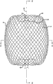
Description of drawings
Fig. 1 is the elevation view of embodiment of device of treatment that is used for patient's vascular system, the inside radial force of wherein a plurality of arrows indications.
Fig. 2 is the elevation view by the cross bar of two simple and easy supporter supports, and wherein a plurality of arrow indications are applied to the power of cross bar.
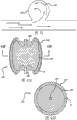
Fig. 3 is the bottom perspective view of an embodiment of device of treatment that is used for patient's vascular system.
Fig. 4 is the elevation view of the device of the treatment of the vascular system that is used for the patient of Fig. 3.
The cross-sectional view of the device of Fig. 4 that Fig. 5 obtains for the line 5-5 in Fig. 4.
Fig. 6 shows the longitudinal section of the device of Fig. 4 that the line 6-6 in Fig. 4 obtains.
The enlarged drawing of the woven filament structure that Fig. 7 obtains for the circle part 7 of from Fig. 5, showing.
The enlarged drawing of the woven filament structure that Fig. 8 obtains for the circle part 8 of from Fig. 6, showing.
Fig. 9 is the near-end figure of the device of Fig. 3.
Figure 10 is the cross-sectional view by the nearside hub portion that installs among the indicated Fig. 6 of the line 10-10 among Fig. 6.
Figure 11 is the elevation view of partial cross section of the far-end of delivery catheter, wherein is mounted with the device of treatment of the vascular system that is used for the patient of Fig. 3 of the restrained condition that is shrinkage.
Figure 12 is the elevation view of the distal part of delivery apparatus or actuator, and it shows some internal structures of said device.
Figure 13 is the elevation view of delivery apparatus of Figure 12 of on internal structure, being added with some tube elements.
Figure 14 is the elevation view of the distal part of the delivery apparatus of Figure 13 of in position having exterior loop and labelling.
Figure 15 is the elevation view of the portions of proximal of said delivery apparatus.
Figure 16 explanation is used for the embodiment of long filament configuration of device of treatment of patient's vascular system.
Figure 17 is that the device of treatment of the vascular system that is used for the patient of catheter guidance sheath (introducer sheath), microtubular and the far-end that is fastened to delivery apparatus or actuator liftedly gets into patient's sketch map.
Figure 18 is the aneurysmal sectional view in top.
Figure 19 is aneurysmal sectional view.
Figure 20 is that said arrow indicates aneurysmal inner nominal vertically to reach lateral dimension with the sketch map in the aneurysm cross section of vertical arrows displaying.
Figure 21 is the sketch map in aneurysm cross section of Figure 20 of sketch map of device with treatment of the vascular system that is used for the patient that is represented by dotted lines, and said device is in free relaxed state, in the horizontal expansion of the outside of aneurysm wall.
Figure 22 is in to launch in the aneurysm and the sketch map in the cross section of the device sketch map that the dotted line by among Figure 21 of part constrained state is represented.
Figure 23 to 26 shows the expansion order of device of the treatment of the vascular system be used for the patient.
Figure 26 A is the enlarged drawing by the cross section of the device of Figure 26 of the circle part 26A among Figure 26 indication, and is illustrated in the formation of thrombosis on the long filament of device.
Figure 26 B further specifies the formation of thrombosis on the long filament of Figure 26 A.
Figure 27 is the elevation view with angle of inclination partial cross section of the embodiment of the device of the treatment of the unfolded vascular system that is used for the patient in aneurysm.
Figure 28 is the elevation view of the partial cross section of the embodiment of the device of the treatment of the unfolded vascular system that is used for the patient in erose aneurysm.
Figure 29 is illustrated in the elevation view in the cross section of the device of the treatment of the unfolded patient's of being used for vascular system in the vascular defects aneurysm.
Figure 30 displaying has the nearside perspective view by the embodiment of the device of the treatment of the vascular system that is used for the patient of the sealing area embodiment of one group of dotted line sign.
Figure 31 to 35 explanation can be used for the various embodiment of Weaving pattern of permeable shell of device of treatment of patient's vascular system.
Figure 36 explains the device of the treatment of the vascular system that is used for the patient that in the permeable shell mechanism of device, comprises the unstructuredness fiber.
Figure 37 is the enlarged drawing of woven unstructuredness fiber in the long filament of permeable shell mechanism.
Figure 38 be used for shown in the elevation view of axle of woven tubular part of the initial embodiment that makes the device that is used to construct the vascular system that supplies the treatment patient of weaving method.
Figure 39 is the elevation view of braiding process that is used for the woven tubular part of manufacturing installation.
Figure 40 is used for the elevation view of partial cross section of embodiment of anchor clamps of woven tubular part of device that thermal finalization is used to make the treatment of the vascular system that supplies the patient.
Figure 41 is used for the elevation view of partial cross section of embodiment of anchor clamps of woven tubular part of device that thermal finalization is used to make the treatment of the vascular system that supplies the patient.
Figure 42 is the elevation view in the cross section of the blood flow of explanation in the aneurysm of patient vessel system.
Figure 43 A is used for the elevation view in cross section of embodiment of device of treatment of patient's vascular system for explanation.
Figure 43 B is the sectional view of the device of Figure 43 A of obtaining along the line 43B-43B of Figure 43 A.
Figure 43 C is the sectional view of device of Figure 43 A that is in the restrained condition of elongation, and its explanation is in permeable shell and the longitudinal length that equates in fact of inner structure of the restrained condition of elongation.
Figure 43 D is the cross-sectional view of the device of Figure 43 C of obtaining along the line 43D-43D of Figure 43 C.
Figure 44 is used for the elevation view of partial cross section of embodiment of device of treatment of patient's vascular system for explanation.
Figure 45 A is used for the elevation view in cross section of embodiment of device of treatment of patient's vascular system for explanation.
Figure 45 B is the cross-sectional view of the device of Figure 45 A of obtaining along the line 45B-45B of Figure 45 A.
Figure 46 is placed in the elevation view in cross section of embodiment of device of the treatment of the vascular system that is used for the patient in the aneurysm for explanation.
Figure 47 is used for the elevation view in cross section of embodiment of device of treatment of patient's vascular system for explanation.
Figure 48 is used for the elevation view in cross section of embodiment of device of treatment of patient's vascular system for explanation.
Figure 49 is the elevation view of embodiment of device of treatment that is used for patient's vascular system.
Figure 50 is the elevation view of embodiment of device of treatment that is used for patient's vascular system.
Figure 50 A is the cross-sectional view of the embodiment of Figure 50 of obtaining along line 50A.
Figure 50 B is the cross-sectional view of the embodiment of Figure 50 A of obtaining along line 50B.
Figure 51 is the elevation view of embodiment of device of treatment that is used for patient's vascular system.
Figure 51 A shows the partial cross section of the embodiment of Figure 51.
Figure 51 B is the cross-sectional view of the embodiment of Figure 51 A of obtaining along the line 51B-51B of Figure 51 A.
Figure 52 is the elevation view of embodiment of device of treatment that is used for patient's vascular system.
Figure 52 A shows the partial cross section of embodiment of the device of the treatment be in the vascular system of showing among Figure 52 of lax expansion state that is used for the patient.
Figure 52 B is the cross-sectional view of the embodiment of Figure 52 A of obtaining along the line 52B-52B of Figure 52 A.
Figure 52 C is for be in the cross-sectional view of the device of the Figure 52 under the axial tensile force effect slightly.
Figure 53 D explanation is in the device of Figure 52 of longitudinal extension state.
Figure 53 is the elevation view of embodiment of device of treatment that is used for patient's vascular system.
Figure 53 A shows the partial cross section of the device of Figure 53.
Figure 53 B is the cross-sectional view of the embodiment of Figure 53 A of obtaining along the line 53B-53B of Figure 53 A.
Figure 54 is the elevation view of embodiment of device of treatment that is used for patient's vascular system.
Figure 54 A shows the partial cross section of the device embodiment of Figure 54.
Figure 54 B is the cross-sectional view of the embodiment of Figure 54 A of obtaining along the line 54B-54B of Figure 54 A.
Figure 55 is the elevation view of partial cross section of embodiment of device of treatment that is used for patient's vascular system.
Figure 55 A is the cross-sectional view of the device of Figure 55 of obtaining along the line 55A-55A of Figure 55.
Figure 55 B shows the device of Figure 55 of the elongation state that is in shrinkage.
Figure 56 is the elevation view of partial cross section of embodiment of device of treatment that is used for patient's vascular system.
Figure 57 explanation is placed in the device embodiment of the Figure 56 in the aneurysm.
Figure 58 is the elevation view of partial cross section of embodiment of device of treatment that is used for patient's vascular system.
The image of the aneurysmal angiogram before Figure 59 A describes to treat.
The aneurysm of Figure 59 A of ten (10) minutes after Figure 59 B describes to treat.
Figure 59 C is illustrated near the patient's aneurysm of showing among Figure 59 A and the aneurysm the mobile border of vascular system inner blood.
Near patient's the mobile border of vascular system inner blood aneurysm that Figure 59 D showed in Figure 59 B after representing to treat in ten (10) minutes and the aneurysm, the wherein border before the dotted line indication treatment.
Figure 60 explains aneurysm with sectional view, and wherein deflection device embodiment is placed in expansible expansion state and adjoins in the aneurysmal intrinsic blood vessel.
Figure 61 shows the aneurysm of Figure 60, and wherein the far-end of the far-end of microtubular and guide line is placed in the aneurysmal internal volume.
Figure 62 shows the aneurysm of Figure 60, and wherein the distally tube head of microtubular is placed in the aneurysm and the distal part of microtubular is settled against expansible deflection device.
Figure 63 explanation be placed in the vascular system that is used for the patient in the aneurysm of showing with section form treatment the macrovoid device embodiment and be placed in the far-end of the microtubular in the internal volume of said device.
Figure 64 explanation is from the device of the treatment of the unfolded vascular system that is used for the patient of the far-end of the microtubular of Figure 63.
Figure 65 explains aneurysm with sectional view, thereby the device of treatment that wherein is used for patient's vascular system launches in aneurysmal internal volume and mobile blocking device is placed in and adjoins said aneurysmal parent artery and seal aneurysmal cervical region.
The specific embodiment
Discuss the device and method of the treatment that is used for vascular defects among this paper, it is suitable for minimally-invasive in patient's vascular system, particularly in patient's cerebral aneurysm, launching.In order this type of embodiment to be delivered to safely and effectively desired therapentic part and to launch effectively; Some device embodiment can be through being configured to be crimped to low section restrained condition, and said restrained condition has and is suitable for sending and by the unfolded lateral dimension of its far-end through the inner chamber of microtubular.The embodiment of these devices also can keep the effective configuration clinically with enough mechanical integrities immediately once expansion, so that As time goes in patient's vascular system, stand power, otherwise said power can cause the deployed device compression.Also need some device embodiment can during OP, block patient's vascular defects acutely so that the more instant feedback about the achievement of treatment is provided to the treatment doctor.Only if state in addition, otherwise in other similar embodiment that one or more characteristics, size or the material of various embodiment can be used for discussing among this paper.
Some embodiment are specially adapted to treat cerebral aneurysm through rebuilding blood vessel wall with the blood flow of completely or partially isolating vascular defects and patient.Some embodiment can be through being configured in vascular defects to launch with the reconstruction that promotes blood vessel wall, bridge joint or both, thus the treatment vascular defects.For among these embodiment some, the permeable shell of said device can be through being configured to said permeable shell grappling or being fixed on useful clinically position.For some embodiment, said device can be placed in the vascular defects whole or in part, so that about blood vessel structure or damaged grappling or fixing said device.Permeable shell can be through opening, cervical region or other part that is configured to cross over vascular defects; So that isolate vascular defects or its part and patient's nominal vascular system, make damaged healing thus or otherwise make the damaged risk minimum of bringing for patient health.
For some of the device of the treatment of the vascular system of discussing among this paper that is used for the patient or whole embodiment, permeable shell can be through being configured to allow the initial perfusion of part blood pass permeable shell.The porosity of permeable shell can be through being configured to isolate fully vascular defects; So that promote damaged healing and isolation, but allow enough initial blood flows through permeable shell so that the mechanical force that reduces or otherwise by the blood in the vascular system or other fluidic dynamic flow device is applied on the minimize membrane.For some embodiment of the device of the treatment of the vascular system that is used for the patient, the part (be sometimes referred to as and stride damaged part) of opening or cervical region that only needs to cross in the permeable shell vascular defects is for permeable and/or useful for the thrombosis in patient's blood flow.For this type of embodiment, opening or cervical region that part of that does not cross over vascular defects in the said device can be impermeable in fact, or excessive so that can not promote thrombotic complete permeable form effectively for hole or opening configuration.In addition, owing to the formation of thrombosis on the long filament of said device, be initially a permeable or semi permeable part for blood flow in the permeable shell and can become impermeable in fact or impermeable fully.In some cases, the thrombosis on the long filament of permeable shell or any other part of said device can be used to reduce aperture or the hole of the permeable shell of complete closed between the long filament.
In general, in some cases, possibly need to use hollow, the thin-walled device with permeable shell of being processed by elastomeric material, it can be constrained for low section in the patient, to send.This type of device also can expansion radially outward after being configured to remove constraint, makes the shell of said device present larger volume, and in vascular defects, launches, with filling or occluding vascular defects otherwise.The expansion radially outward of said shell can be used to engage some of vascular defects or whole inner surfacies, and the mechanical friction between the inner surface of the outer surface of the permeable shell of said device and vascular defects is anchored on said device in the vascular defects effectively whereby.Some embodiment of this device also can mechanically be trapped in the intracavity of vascular defects partially or completely, especially said damaged when having narrow neck and partly reaching big internal volume.For the low section realizing being used to send and volume and in order to have high volume expanded ratio; Some device embodiment comprise by matrix woven or that braided filament constitutes; Said woven or braided filament is coupled in together through pilotaxitic texture; Form the permeable shell of self expandable formula thus, it couples a little or has regular intervals and stable hole or patterns of openings in fact between the intersection point long filament, still allows concordance (conformity) and volume constraint simultaneously.
As used herein, term is woven and weave interchangeable use, and expression makes long filament form any intertexture form of network.In textile and other industry, depend on product or application, for example article are laminated or cylindrical form, and these terms can have difference or more specific implication.For purposes of the present invention, interchangeable these terms of use.
For some embodiment, for the woven or litzendraht wire blocking device of the treatment of the vascular system that is used for the patient that can in the endovascular treatment of cerebral aneurysm, realize desired clinical effectiveness, three factors can be crucial.We find; In order effectively to use in some applications; Possibly need implanting device to have enough radial rigidities (being used to stablize), limited aperture (be used near acute (in the program) block) completely, and enough little shrinkage section (in order to allow to be inserted through the inner chamber of microtubular).In some cases, the device with the radial rigidity that is lower than certain threshold value can be unsettled, and takes place that non-desired move and form the risk of thromboembolism in the zone errors of vascular system maybe be higher.Hole between the long filament intersection point in braiding or the machine-knitted structure more greatly maybe not can produce thrombosis and can not be under acute environment occluding vascular defects, and therefore can't provide flow damage will cause clinical feedback to treatment doctor or sanitarian to the complete and persistent obstruction of the vascular defects of being treated.In order to get into the mode of treatment doctor custom and to pass through crooked cerebrovascular system, the device of sending the treatment of the vascular system that is used for the patient through the standard microtubular can be desirable especially.
For some embodiment, possibly need to use long filament to form permeable shell, so that produce the desired configuration of discussing more in detail like hereinafter with two or more different-diameter or lateral dimension.The radial rigidity of the device that two kinds of long filaments (two kinds of different diameters) are woven can be expressed as the function of long filament number and its diameter, and is as follows:
S
Radially=(1.2 * 10
6Lbf/D
4) (N
1d
1 4+ N
sd
s 4)
S wherein
RadiallyBe radial rigidity in ft lbf (lbf),
D is assembly dia (lateral dimension),
N
1Be big long filament number,
N
sBe little long filament number,
d
1Be diameter in the big long filament of inch, and
d
sBe diameter in the little long filament of inch.
Some embodiment for having special clinical value use this expression formula, radial rigidity S
RadiallyCan about 0.014 and 0.284lbf power between.
Some useful embodiment for the woven line apparatus of the treatment of the vascular system that is used for the patient; Desirable situation is that the maximum diameter of hole in the device in the part of the cervical region of leap vascular defects or opening can be expressed as the function of total number, filament diameter and the assembly dia of all long filaments.When using two or more filament diameter or lateral dimension, in device, under the minimum certain situation of long filament size compared plant bulk, can ignore the difference between the long filament size.For two filament plants (that is, the device of making by the long filament of two kinds of different sizes), can use minimum filament diameter to calculate.Therefore, the maximum diameter of hole of this type of embodiment can be represented as follows:
P
max=(1.7/N
T)(πD-(N
Td
w/2))
Its P
MaxBe average pore size,
D is that device is straight through (lateral dimension),
N
TBe the total number of all long filaments, and
d
wBe diameter in the long filament (minimum) of inch.
For some embodiment, use this expression formula, the maximum diameter of hole P of any other suitable part of the part of the opening of leap vascular defects or cervical region or device in the device
MaxCan be less than about 0.016 inch or about 400 microns.In certain embodiments, the maximum diameter of hole of striding damaged part or any other suitable part of device can be less than about 0.012 inch or 300 microns.
The shrinkage section (section with two kinds of different filament diameters) of the filament plant that two kinds of long filaments are woven can be expressed as function:
P
c=1.48((N
1d
1 2+N
sd
s 2))
1/2
Wherein, P
cBe the shrinkage section of device,
N
1Be the number of big long filament,
N
sBe the number of little long filament,
d
1Be diameter in the big long filament of inch, and
d
sBe diameter in the little long filament of inch.
Some embodiment for having special clinical value use this expression formula, the shrinkage profile P
cCan be less than about 1.0mm.In having some embodiment of special clinical value, said device can be through structure to have above all three the factor (S in the scope that preceding text are discussed
Radially, P
MaxAnd P
c); Side by side, S
RadiallyBetween about 0.014lbf and 0.284lbf, P
MaxLess than about 300 microns and P
cLess than about 1.0mm.In some said embodiment, said device can be through making to comprise that about 70 threads are to about 300 threads.In some cases, said long filament can have about 0.0004 inch to about 0.002 inch outside lateral dimension or diameter.
Such as argumentation, some embodiment of device of treatment that are used for patient's vascular system need adjust said device size for the size near (or size is slightly larger than) vessel position, to fill said vessel position.Can suppose device is scaled to large-size and uses bigger long filament will satisfy the requirement of this type of big embodiment of device.Yet for the treatment of cerebral aneurysm, radially the diameter of the device of shrinkage or section receive the conduit size restrictions, and said conduit size can be passed through in little, the crooked blood vessel of brain effectively.In addition, because the device that uses the elastic filament of the given or fixed number with intended size or thickness to make is bigger, so that hole between the long filament joint or opening correspondingly become is big.In addition, for given long filament size, long filament the and therefore flexural modulus (flexural modulus) or the rigidity of said structure increase and reduce along with plant bulk.Flexural modulus may be defined as the ratio of stress and strain.Therefore, if strain under given force (amount of deflection) is lower, can think that then device has high flexural modulus or harder.Can think that also hard device has low compliance (compliance).
The vascular system that is used to treat the patient for the device that disposes large-size is suitably set up model and can be useful put on power on the said device in less than the vessel position of the nominal diameter of the device that is in lax no restrained condition or lateral dimension or damaged (for example blood vessel or aneurysm) during expanding unit at diameter or lateral dimension.Such as argumentation, in some cases, desirable is to make device " oversize ", so that between the inner surface of the outer surface of said device and blood vessel wall, have residual power.Among Fig. 1 schematic illustration by oversize cause put on the inside radial force on the device 10, the inside radial force of arrow 12 expressions among the figure.Such as among Fig. 2 displaying, put on these compression stresses on the long filament 14 of the device among Fig. 1 and can be modeled as and have the distributed load showed like the arrow among the figure 18 or the simple and easy support rail 16 of power.Visible from the equality of following amount of deflection about cross bar with two simple and easy supporters 20 and distributed load, amount of deflection is the function of 4 powers of length L:
Amount of deflection=the 5FL of cross bar
4/ 384 EI
F=power wherein,
The length of L=cross bar,
E=Young's modulus (Young ' s Modulus), and
The I=rotary inertia.
Therefore, along with device size increases and the L increase, compliance increases in fact.Therefore when will install 10 when being inserted in the vessel position (for example blood vessel or aneurysm), for the device compression of specified rate or oversize, the outer surface that installs 10 long filament 14 resists restraining forces and the outside radial force that applies is lower.This power is very important with the risk that the reduction device moves and potential distal embolization forms for guaranteeing device stability in some applications.
In certain embodiments, can use the combination manufacturing of little long filament size and big long filament size to have desired radial compliance and also have device through the shrinkage section of the inner chamber that is configured to be fit to pass microtubular commonly used.Compare the device of all making, even the device made from a small amount of relatively large long filament 14 also can provide the radial compliance that reduces (or the rigidity that increases) with little long filament.Because in the variation that does not increase the rotary inertia that is caused by the diameter increase under total cross-sectional area situation of long filament, even the big long filament of relatively small amount also can provide the significantly increase of bending stiffness.The rotary inertia (I) of circle line or long filament can be defined by following equality:
I=∏d
4/64
Wherein d is the diameter of line or long filament.
Because rotary inertia is the quadruplicate function of filament diameter, the less variation of diameter can greatly increase rotary inertia.Therefore the less variation meeting of long filament size is to the amount of deflection constant load under and have tremendous influence to installing compliance thereupon.
Therefore, under the situation that the cross-sectional area of device 10 shrinkage section does not significantly increase, can significantly increase rigidity.Because make when implementing with treatment than large aneurysm than bigger device, this can be particular importance.Though big cerebral aneurysm maybe be rare relatively, because compare less aneurysm, the current more available embolization devices of doctor have relatively poor relatively effect, so it has proposed an important therapeutics challenge.
Therefore, can use and have many different-diameters the combination of the long filament 14 of (for example 2,3,4,5 or more kinds of different-diameter) or lateral dimension to be formed for some embodiment of device of treatment of patient's vascular system.In the device embodiment of the long filament that uses two kinds of different-diameters; Some bigger long filament embodiment can have about 0.001 inch and arrive about 0.004 inch lateral dimension; And some little long filament embodiment can have about 0.0004 inch and about 0.0015 inch lateral dimension or diameter; More particularly, can be about 0.0004 inch to about 0.001 inch.Some structures can be used the long filament that has up to about 0.001 inch lateral dimension.The ratio of the number of big long filament and the number of little long filament can be between about 2 to 12, and also can be between about 4 to 8.In certain embodiments, the difference of diameter or lateral dimension aspect can be less than about 0.004 inch between big long filament and the less long filament, more particularly, less than 0.0035 inch, and even more particularly, less than 0.002 inch.Discuss substantially like preceding text, make wired or long filament all to satisfy the parameter of the various relations of discussing among this paper always necessary.When a large amount of relatively long filaments was used to various structure, this point was correct especially.In some cases, when most of long filaments of permeable shell or inner structure satisfied dimension constraint, filament structure can satisfy the relation constraint of discussing among this paper.
Such as preceding text argumentation, the device embodiment 10 of treatment that is used for patient's vascular system can comprise a plurality of lines, fiber, thread, pipe or other long filament element that forms as the structure of permeable shell.For some embodiment, can be by this type long filament through connecting or the end of fastening tubulose braiding structure forms spherical form.For this type of embodiment, the braiding or the density of machine-knitted structure can increase near having compiled line or long filament 14 ends place or end inherently, and near the near-end that is placed in permeable shell 40 32 and far-end 34 mid portion 30 places or its before, reduce.For some embodiment, an end of permeable shell 40 or any other suitable part can be positioned in opening or the cervical region of vascular defects (for example aneurysm) to be used for treatment.Therefore, braiding or the woven filament plant that has a permeable shell can not need add different in kind and strides damaged structure to realize the hemostasis and the obstruction of vascular defects in the independent of the character of the nominal section of said permeable shell.Can make this filament plant through braiding, long filament manufacturing technology woven or that other is suitable.This device embodiment can be shaped as the multiple 3D shape of discussing among this paper.
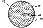
Referring to Fig. 3 to 10, show the embodiment of device of the treatment of the vascular system be used for the patient.Device 10 comprises the permeable shell 40 of self expandable formula elasticity; Permeable shell 40 has near-end 32, far-end 34, the longitudinal axis 46; And further comprise many elasticity of elongation long filaments 14; As showing in more detail among Fig. 5,7 and 18 that elastic filament 14 comprises big long filament 48 and the little long filament 50 with at least two kinds of different lateral dimensions.Long filament 14 has machine-knitted structure and relative to each other fastening at its near-end 60 and far-end 62.The permeable shell 40 of said device has the elongation state of radial constraint; Be configured for use in microtubular 61 (such as among Figure 11 displaying) in send, wherein thin woven long filament 14 extends lengthwise into far-end 44 from near-end 42 along the length of long filament with radially adjoining each other.
Such as among Fig. 3 to 6 displaying, permeable shell 40 also has the relaxed state of expansion of the configuration of and vertical shortening spherical in shape with respect to said radial constraint state.Under expansion state, woven long filament 14 forms the permeable shell 40 of self expandable formula elasticity along the smooth paths from the longitudinal axis 46 radial dilatation of device between near-end 32 and the far-end 34.The machine-knitted structure of long filament 14 is included in a plurality of openings 64 that between woven long filament, form in the permeable shell 40.For some embodiment, the maximum in the opening 64 can be through being configured to allow blood only to cross said opening with the velocity flow that is lower than thrombotic threshold velocity.Time mean speed when thrombotic threshold velocity is defined as blood vessel graft at least to a certain extent and when launching in the vascular system the patient, is covered by thrombosis more than 50% graft surface.Under the situation of aneurysm occlusion, it is suitable that different slightly threshold values can be.Therefore; In the time of should being included in patient's the vascular system expanding unit (for example installing 10) like thrombosis threshold velocity used herein in the said device or device go up blood coagulation take place, make blood flow in the vascular defects of the treating speed when blocked in fact in less than about 1 hour or during treatment procedure that gets into through said device.In some cases; At the upper reaches with the contrast medium injection of capacity implantation position in patient's the vascular system; And after it was observed when dissipate in said position, the contrast medium that intravasation is damaged seldom can indicate the blood flow of intravasation in damaged blocked.The said acute occlusion that in less than about 1 hour or in the lasting obstruction of implant procedure duration blood flow, also can be described as vascular defects.
Therefore, launch in case install 10, any blood that flows through permeable shell be with can being slowed to the speed that is lower than the thrombosis threshold velocity, and will begin on the opening in permeable shell 40 and said around openings formation thrombosis.Finally, this process can be through being configured in the vascular defects of expanding unit 10, to produce acute occlusion.For some embodiment, the far-end of permeable at least shell 40 has the back-flexing that is the eversion type configuration, makes the fastening far-end 62 of long filament 14 in permeable shell mechanism of the nominal that is in expansion state or profile, axially stretch out.For some embodiment, the near-end of permeable shell further comprises the back-flexing that is the eversion type configuration, makes the fastening near-end 60 of long filament 14 in the permeable shell mechanism 40 of the nominal that is in expansion state, axially stretch out.As used herein, term turns up and can comprise that turning up of showing among the device embodiment like Fig. 3 to 6, part are turned up and/or through back-flexing and recessed structure.For this type of embodiment, be placed in the two ends of the long filament 14 of permeable shell or wheel hub structure around end 60 and 62 can be in the spherical edge of the permeable shell of said device or below stretch out.
The elasticity of elongation long filament 14 of permeable shell 40 can be relative to each other fastening at its near-end 60 and far-end 62 places through one or more methods (comprise melting welding, welding, bonding, epoxy is bonding or similar approach).Except that the end of long filament tightened together, distally wheel hub 66 also can be fastened to the far-end 62 of the filament 14 of permeable shell 40, and nearside wheel hub 68 is fastened to the near-end 60 of the filament 14 of permeable shell 40.Nearside wheel hub 68 can comprise a kind of cylindrical parts, and said cylindricity parts extend to adjacent to beyond the near-end 60 of filament, in the portions of proximal of nearside wheel hub 68, form chamber 70 thus.Proximal chamber 70 can be used for the fixing binding agent; For example epoxy resin, scolder or any other suitable binding agent; With the removable tethers (elongate detachment tether) 72 that is used for fastening elongation, removable tethers 72 removably is fastened to delivery device again, for example shows among Figure 11 to 15.
For some embodiment, the elasticity of elongation long filament 14 of permeable shell 40 can have circular in fact cross section, and is made by elastic material (also can be shape memory metal).But the spherical arrangement of the expansion state that the shape memory metal thermal finalization of the long filament of permeable shell 40 becomes to relax is as showing among Fig. 3 to 6.Suitable super-elastic shape memory metal can comprise alloy, for example NiTi alloy and analog thereof.The super-elasticity character of this type of alloy can be used for making elongate filament 14 to have elasticity; But so that the complete affined sphere that said long filament thermal finalization becomes to be showed; In the interior tube chamber of microtubular, send being used for; And unclamp at once after then in patient's body, launching, self expandable reverts back to the primary in fact thermal finalization shape of spherical arrangement.
The near-end 60 of at least some long filaments 14 of permeable shell 40 can be fastened to nearside wheel hub 68; And the far-end 62 of at least some long filaments 14 of permeable shell 40 can be fastened to distally wheel hub 66; Wherein nearside wheel hub 68 and distally wheel hub 66 and the coaxial in fact arrangement of the longitudinal axis 46 are as showing among Fig. 4.The end of long filament 14 can be through preceding text about being fastened to corresponding wheel hub 66 and 68 with in the long filament end method of discussing secured to one another (comprise and use binding agent, scolder, welding and analog thereof) any one.Such as Figure 11 displaying, the mid portion 30 of permeable shell 40 can have first lateral dimension and the low section that is suitable for being sent by microtubular.Can apply through the inner surface (distal portions of the microtubular of for example being showed 61) of tube chamber in the microtubular installing 10 radial constraint, or it can when discharging, the far-end of conduit apply through any other the suitable mechanism that can controlled manner removes at device 10.In Figure 11, the far-end of the elongation delivery device 110 of the delivery system 112 that the near-end of device 10 or wheel hub 68 are fastened to nearside wheel hub 68 places that are placed in device 10.
Some device embodiment 10 with braiding or woven filament structure can use about 10 threads to about 300 threads 14, and more particularly about 10 threads are to about 100 threads 14, and even more particularly about 60 threads form to about 80 threads 14.Some embodiment of permeable shell 40 can comprise about 70 threads that extend to far-end 34 from near-end 32 to about 300 threads, more particularly from near-end 32 extend to far-end 34 about 100 to about 200 threads.For some embodiment, long filament 14 can have about 0.0008 inch and arrive about 0.004 inch lateral dimension or diameter.Elasticity of elongation long filament 14 can have about 0.0005 inch to about 0.005 inch in some cases, more particularly about 0.001 inch to about 0.003 inch, and about in some cases 0.0004 inch to about 0.002 inch outside lateral dimension or diameter.Some device embodiment 10 for the long filament that comprises different size 14; The big long filament 48 of permeable shell 40 can have about 0.001 inch and arrive about 0.004 inch lateral dimension or diameter; And little long filament 50 can have about 0.0004 to about 0.0015 inch, and more particularly about 0.0004 inch is arrived about 0.001 inch lateral dimension or diameter.In addition, the lateral dimension between little long filament 50 and the big long filament 48 or the difference of diameter can be less than about 0.004 inches, more particularly, less than about 0.0035 inch, and even more particularly, less than about 0.002 inch.Embodiment for the permeable shell 40 of the long filament that comprises different size 14; The number of the little long filament 50 of permeable shell 40 can be about 2 to 1 to about 15 to 1 than the number of the big long filament 48 of permeable shell 40; More particularly; About 2 to 1 to about 12 to 1, and even more particularly, about 4 to 1 to about 8 to 1.
The relaxed state of the expansion of permeable shell 40 (such as among Fig. 4 displaying) have the configuration of axially shortening with respect to restrained condition, make and compare when being in restrained condition that nearside wheel hub 68 more approaches distally wheel hub 66 and settles.Wheel hub 66 and 68 both and the coaxial in fact arrangement of the longitudinal axis 46 of said device, and each long filament element 14 is formed on the level and smooth arc that each end place has back-flexing between nearside wheel hub 66 and distally wheel hub 68.For some embodiment, nearside wheel hub 66 and the advance between the distally wheel hub 68 that is in the permeable shell 40 of unfolded relaxed state can be about 25% to about 75% of the advance between the nearly measuring wheel hub 66 and distally wheel hub 68 when being in affined cylindrical state.The arc that is formed by long filament 14 between near-end 32 and the far-end 34 can be through being configured to make the mid portion of each long filament 14 to have in fact second lateral dimension greater than first lateral dimension.
For some embodiment, permeable shell 40 can have first lateral dimension of about 0.2mm to the radial constraint state that is in shrinkage of about 2mm, and about 4mm is to second lateral dimension of the lax expansion state of being in of about 30mm.For some embodiment, second lateral dimension that is in the permeable shell 40 of expansion state can be about 2 times to about 150 times of first lateral dimension, more particularly, is first or about 10 times or about 25 times of affined lateral dimension.Near-end 32 and the advance between the far-end 34 that is in the permeable shell 40 of lax expansion state can be about 25% to about 75% of the spacing between the near-end 32 and far-end 34 when being in affined cylindrical state.For some embodiment, the main lateral dimension that is in the permeable shell 40 of lax expansion state can be about 4mm to about 30mm, and more particularly, about 9mm arrives about 15mm, and even more particularly, about 4mm arrives about 8mm.
Such as among Fig. 6 displaying, the arch section of the long filament 14 of permeable shell 40 can be near the end of permeable shell 40 and has first or outer radius 88 and second or the similar sinusoidal shape of inside radius 90.The shape of this similar sine curve or many curves can provide concave surface in near-end 32, said concave surface can reduce adjoining the obstruction that carries the stream in the tumor blood vessel of vascular defects.For some embodiment, first radius 88 of permeable shell 40 and second radius 90 can be between about 0.12mm and about 3mm.For some embodiment, the distance between near-end 32 and the far-end 34 can be less than about 60% (for some embodiment) of the total length of permeable shell 40.When device 10 met obstructions at far-end 34 places, this configuration can allow far-end 34 towards near-end 32 downward flexings and so vertical adaptability (longitudinal conformance) can be provided.In certain embodiments, long filament 14 can be through being shaped so that in greater than the distance of 2mm, there is not the part of curvature.Therefore, for some embodiment, each long filament 14 can have successive in fact curvature.This successive in fact curvature can provide level and smooth expansion and can reduce the risk of vascular puncture.For some embodiment, the withdrawals or the degree of turning up can be greater than another persons in the end 32 or 34, so that an end is gone up in the vertical or axially and had more adaptability than the other end.
For some embodiment, first radius 88 of permeable shell 40 and second radius 90 can be between about 0.12mm and about 3mm.For some embodiment, the distance between near-end 32 and the far-end 34 can greater than the expansion permeable shell 40 total length about 60%.Therefore, the maximum fore-and-aft distance between the inner surface can be device 10 outer surfaces longitudinal length or total length about 60% to about 90%.When installing 10 when far-end meets obstructions, the gap between the wheel hub 66 and 68 at near-end 32 and far-end 34 places can allow distally wheel hub 66 towards nearside wheel hub 68 downward flexings, thereby vertical adaptability is provided.Long filament 14 can be through being shaped so that in greater than the distance of about 2mm, there is not the part of curvature.Therefore, for some embodiment, each long filament 14 can have successive in fact curvature.This successive in fact curvature can provide level and smooth expansion and can reduce the risk of vascular puncture.Far-end 34 withdrawals or the degree of turning up can make the distal portions of permeable shell 40 to have more adaptability than proximal part in the axial direction greater than near-end 32.The adaptability of distal portions can make device adapt to erose aneurysm or other vascular defects better.The nonreentrant surface of said device is flexing inwardly, forms recessed surface to meet the curvature of vessel position.
Figure 10 shows the enlarged drawing of the long filament 14 in the nearside wheel hub 68 be placed in device 10, and the long filament 14 that wherein has two kinds of different sizes is by the outer shroud constraint of nearside wheel hub 68 and parcel tightly.Such as among Fig. 6 displaying, tethers parts 72 can randomly be placed in the mid portion of long filament 14 or in the chamber 70 of the nearside wheel hub 68 of the near-end 60 of adjacent filaments 14.The link 92 that the far-end of tethers 72 can form in its far-end is fastening, and said link 92 is mechanically to be trapped in the chamber 70 of nearside wheel hub 68, and said chamber 70 is formed by the nearside shoulder portion 94 of nearside wheel hub 68.The far-end 92 of the knotting of tethers 72 mechanical compress also capable of using, bonding, melting welding, welding, brazing or similar approach are through with the far-end of tethers 72 bonding or be packaged in the chamber 70 and randomly among the near-end 60 of long filament 14, come fastening.The far-end 92 of the knotting of the tethers embodiment 72 that shows among Fig. 6 with adhesive package in the chamber of nearside wheel hub 68.This tethers 72 can be soluble, that can cut off or dissoluble tethers, said tethers can be the part like the delivery device of showing among Figure 11 and Figure 23 to 26 that is used for expanding unit 10 110.Figure 10 also shows and is placed in the nearside wheel hub 68 and by the big long filament 48 and the little long filament 50 of nearside wheel hub 68 constraints, and nearside wheel hub 68 can be through being configured to big long filament 48 and little long filament 50 relative to each other are fastened on the outer intra-annular suitable place of nearside wheel hub 68.
Fig. 7 and 8 explanations are used for some configuration embodiment of braided filament 14 of permeable shell 40 of device 10 of treatment of patient's vascular system.In each embodiment, braiding structure shows with the circles in the hole that is placed in woven or braiding structure 64 100, and wherein said circular 100 contact with long filament section that each adjoins.Aperture size part is at least determined by the size of the long filament element 14 of fabric, the angle filling density overlapping and the per inch braiding structure that long filament relative to each other forms.For some embodiment; Mesh (cell) or opening 64 can have the shape that assumes diamond in shape in fact like the elongation of showing among Fig. 7; And such as among Fig. 8 displaying, the hole of permeable shell 40 or opening 64 can have towards device 10 mid portion 30 in fact more near foursquare shape.Rhombohedral hole or opening 64 can have in fact the length greater than width, especially near wheel hub 66 and 68.In certain embodiments, for some meshes, the length of rhombus hole or opening can surpass 3 to 1 ratio with the ratio of width.Diamond opening 64 can have the length greater than width, has the length-width ratio (being defined as length/width) greater than 1 thus.Such as among Fig. 7 displaying, near the opening 64 wheel hub 66 and 68 can have in fact the length-width ratio greater than the said wheel hub of distance opening far away.The length-width ratio of adjoining the opening 64 of said wheel hub can be greater than about 4 to 1.For some embodiment, can be between about 0.75 to 1 and about 2 to 1 near the length-width ratio of the opening the maximum gauge 64.For some embodiment, the length-width ratio of permeable shell 40 split sheds 64 can be about 0.5 to 1 to about 2 to 1.
For some embodiment; Size range by maximum circular 100 apertures defined that can not make long filament 14 displacements or distortion around the opening 64 in the opening of the braiding structure that can be placed in permeable shell 40 64 simultaneously can be about 0.005 inch to about 0.01 inch; More particularly; About 0.006 inch to about 0.009 inch, even more particularly, about 0.007 inch to about 0.008 inch.In addition, at least some can be through being configured to allow blood only to cross opening 64 with the velocity flow that is lower than thrombotic threshold velocity in the opening 64 that between the adjacent filament 14 of device 10 permeable shell 40, forms.For some embodiment, the maximum open 64 in the permeable shell mechanism 40 can be through being configured to allow blood only to cross opening 64 with the velocity flow that is lower than thrombotic threshold velocity.Such as preceding text argumentation, for some embodiment, said aperture can be less than about 0.016 inch, more particularly, less than about 0.012 inch.For some embodiment, the opening 64 that between the long filament that adjoins 14, forms can be about 0.005 to about 0.04 inch.
Referring to Figure 12 to 15, show the delivery device embodiment 110 of the delivery system 112 of Figure 11 in more detail.Such as among Figure 12 displaying, equipment 110 comprises elongation heart yearn 114, the near-end 116 of elongation heart yearn 114 slave units 110 extends to the distal section 118 of equipment 110.Heart yearn 114 promotes to be used for the interior tube chamber 120 of affined device 10 through the microtubular 61 of the delivery system 112 showed like Figure 11 of treatment of patient's vascular system through the fracture strength that is configured to provide enough.Heart yearn 114 also has enough tensile strength and extracts out from the position in microtubular 61 outsides or withdraw and get in the axial direction in the interior tube chamber 120 of microtubular 61 in nearside ground will install 10.Such as among Figure 13 displaying; The tethers 72 that extends from nearside wheel hub 68 nearside ground is fastened to the far-end of heart yearn 114 with the collapsible tube 122 of certain-length; Collapsible tube 122 is to be placed on the distal section of a part and heart yearn 114 of tethers; And on both, shrink, but can use any other suitable clamp structure.
The heater coil 124 that is electrically coupled to first conductor 126 and second conductor 128 is placed on the farthest side part of tethers 72.The polymer pipe 130 that heater coil 124 can also be placed in the certain-length on the heater coil 124 of heat-shrinkable tube 122 far-ends covers, and said polymer pipe 130 is used for serving as thermodynamic barrier and the heat that leaks into the surrounding (for example patient's blood flow) of delivery device 110 from heater coil 124 is minimized.Such as among Figure 13 displaying, in case heat-shrinkable tube 122 and adiabatic polymerisation property management 130 are secured to the distal section 118 of equipment 110, just can prune the portions of proximal of the tethers 72 that proximity thermal collapsible tube 122 settles.The ceoncentrically wound coil (over coil) 132 that extends to the proximal section 136 of equipment 110 from the far-end 134 of delivery device 110 can then be positioned on heater coil 124, heart yearn 114, tethers 72, first conductor 126 and second conductor 128 so that these elements are retained on together, produces the outer surface of low-frictional force and keeps the desired flexibility of delivery device 110.Such as among Figure 15 displaying; The proximal section 136 of equipment 110 comprises the near-end of the ceoncentrically wound coil 132 in the distally that is placed in first contact, 138 and second contact 140; Said first contact, 138 and second contact 140 is settled around the proximal section 136 of heart yearn 114 along circumference, with its isolation and be electrically coupled to first conductor 126 respectively and second conductor 128.
The embodiment of delivery device 110 generally can have the length greater than the total length of the microtubular that is intended for use delivery system 112 61.This relation allows delivery device 110 to extend from interior tube chamber 120 remote port of microtubular 61 together with the device that is fastened to its far-end 10; The doctor has near-end 150 extensions (Figure 17 of hereinafter discussing show) of sufficient length simultaneously, so that can operate on it from microtubular 61.For some embodiment, the length of delivery device 110 can be about 170cm to about 200cm.Heart yearn 114 can be by any suitable high-strength material manufacturing, for example rustless steel, NiTi alloy or analog.The embodiment of heart yearn 114 can have about 0.010 inch and arrive about 0.015 inch external diameter or lateral dimension.Ceoncentrically wound coil 132 can have about 0.018 inch and arrive about 0.03 inch external diameter or lateral dimension.Though the apparatus embodiments 110 of showing among Figure 12 to 15 by activating through the right electric energy of conductor, uses heater block or element (for example heater coil 124) that the similar configuration through the luminous energy of optical fiber or any other suitably-arranged can be used for long-range heating distally to cut off the distal part of tethers 72.In addition, also discuss and incorporate into other delivery device embodiment of device embodiment 10 of treatment of any patient's of being used for who also can be used for discussing in this article vascular system among this paper.
Other is sent and navigation system embodiment can be provided at not along the whole length of delivery device and shifts under the situation of moment, and rotation is used to treat the ability of device of patient's vascular system in vivo.Be used for device 10 send and more localized embodiment are described in the International PCT patent application case that PCT/US2008/065694 number of incorporating preceding text into own together.Said send and positioning equipment can comprise the distally rotary part, said distally rotary part is not rotating implant in vivo under the situation of the whole length transmission torque of said equipment.Randomly, whether delivery system also can rotate implant under the situation of transmission torque in the mid portion between the rotatable end of near-end and distally or not.Said send and navigation system can be fastened to any suitable part of device of the treatment of the vascular system that is used for the patient liftedly.
The device embodiment that discusses among this paper can remove from any suitable flexibility, the delivery device or the actuator (the for example structure of lead or similar lead) of elongation.Device embodiment from then on delivery device releasing can through hot mechanism (such as preceding text argumentation), known any other mechanism activates in electrolysis mechanism, hydraulic mechanism, shape-memory material mechanism or the blood vessel implant expansion technique.
Be used for the expansion of therapy equipment and the embodiment of releasing (for example in patient's vascular system, launching embolization device or support) and can comprise the distal part that this type of device is connected to propeller or other delivery device parts via dissoluble connection.Therapy equipment 10 can be releasably attached to the distal part of said equipment through thread tethers 72, cord, thread, line, stitching thread, fiber or the analog that preceding text can be described as tethers.Tethers 72 can be monofilament, bar, silk ribbon, hollow pipe or analog form.Some embodiment of tethers can have diameter or the maximum ga(u)ge between about 0.05mm and 0.2mm.Tethers 72 can be through being configured to stand the maximum tensile load between about 0.5kg and 5kg.For some embodiment, possibly make some known provisions for disengagement can lack enough tensile strength, and can't be used for some embodiment that this paper discusses in fact greater than some embolization devices owing to the quality of deployed device 10.Therefore, for some tethers embodiment that have greater than about 15 newton's " fracture load (load at break) ", the fubril that working strength is very high is desirable.For some embodiment, can use (can be from the tethers of the material manufacture of Heerlen, Holland (Heerlen, imperial DSM group (Royal DSM) Netherlands) buys) by being called that the enlightening Nima is general and carrying (Dyneema Purity).
Many materials can be used for making tethers embodiment 72, comprise polymer, metal and its complex.The one type of material that is applicable to tethers comprises polymer; For example polyolefin, polyolefin elastomer (for example polyethylene, polyester (PET), polyamide (nylon (Nylon)), polyurethane, polypropylene), block copolymer (for example PEBAX or Hai Qu (Hytrel), and ethylene-vinyl alcohol (EVA)); Or type elastomeric material, for example (Kraton) rises in silicone, latex and section.In some cases, said polymer also can use crosslinking with radiation to operate its hot strength and fusion temperature.The another kind of material that can be used for tethers embodiment can comprise metal, for example Nitinol (Nitinol (Nitinol)), gold, platinum, tantalum and steel.Other material that is applicable to the structure tethers comprises the Wholly aromatic polyester polymer, and said Wholly aromatic polyester polymer is for can provide high performance properties and to have highly inert liquid crystal polymer (LCP).Commercially available LCP polymer is Wei Kean (Vectran), and it is produced by Kuraray company (Kuraray Co.) (Tokyo).Said material chosen can be depending on fusing or softening temperature, the power that is used to dismantle and body treatment position.Said tethers can join implant and/or propeller to through known other method in curling, welding, knotting, welding (knot tying), bonding or this technology.
It shall yet further be noted that many changes for long filament and nearside wheel hub structure (for example preceding text are described in detail about Figure 10) all can be used for supplying the useful embodiment of device 10 of treatment of patient's vascular system.Figure 16 shows the enlarged drawing of the cross section of nearside wheel hub configuration.For the embodiment that is showed, long filament 14 is placed in nearside wheel hub 68 or installs in 10 the end sections, and wherein long filament 14 is by the outer shroud constraint of nearside wheel hub 68 and parcel tightly.Tethers parts 72 can be placed in the mid portion of long filament 14 or are placed in the intracavity of nearside wheel hub 68 of the near-end 60 of adjacent filaments 14.This tethers 72 can be soluble, that can cut off or dissoluble tethers, said tethers can be the part of the releasing equipment that is used for expanding unit as discussed above.
Figure 16 explains the cross section of the embodiment of nearside wheel hub 68, and its displaying can tightly be wrapped up through the inner surface of wheel hub 68 and the configuration of the filament of radial constraint.The braiding of the permeable shell 40 that is formed by this type long filament 14 in certain embodiments, or the little long filament that machine-knitted structure can use greater number are constructed.The number of long filament 14 can be greater than 125 and also can be between about 80 threads and about 180 threads.Such as preceding text argumentation, for some embodiment, the total number of long filament 14 can be about 70 threads to about 300 threads, more particularly, for about 100 threads to about 200 threads.In certain embodiments, the braiding structure of permeable shell 40 can use the long filament 14 of two or more size to construct.For instance, said structure can have some big long filaments so that support structure to be provided, and has some less long filaments so that desired aperture and density to be provided, and therefore provides flow resistance to realize thrombotic threshold velocity in some cases.For some embodiment, the little long filament 50 of permeable shell 40 can have about 0.0006 inch to about 0.002 inch (for some embodiment) and about 0.0004 inch lateral dimension or diameter to about 0.001 inch (in other embodiments).Big long filament 48 can have about 0.0015 inch lateral dimension or diameter that arrives about 0.004 inch (in other a little embodiment) to about 0.004 inch (in certain embodiments) and about 0.001.Long filament 14 can plain woven (that is, one next on structure), and (showing among Fig. 7 and 8) or the mode of complementary woven (supplementary weave) (an above warp thread and one or more weft yarns interweave) weave.Filling density (pick count) can change between per inch about 25 and 200 latitude numbers (PPI).
For some embodiment, permeable shell 40 or its several portions can be porous and can be highly permeable for liquid.Compare when under 120mmHg pressure, measuring, to have usually and be lower than 2,000ml/min/cm
2The most of blood vessel prosthesis fabrics or the graft of water penetration, the permeable shell 40 of some embodiment that discuss among this paper can have greater than about 2,000ml/min/cm
2, in some cases greater than about 2,500ml/min/cm
2Water penetration.For some embodiment, when under 120mmHg pressure, measuring, the water penetration of permeable shell 40 or its several portions can be about 2,000 and 10,000ml/min/cm
2Between, more particularly, for about 2,000ml/min/cm
2To about 15,000ml/min/cm
2
Device embodiment and assembly thereof can comprise metal, polymer, biomaterial and complex thereof.Suitable metal comprises alloy, cochrome, Nitinol, platinum, tantalum, rustless steel, titanium, gold and the tungsten based on zirconium.Possible suitable polymers includes, but is not limited to acrylic acid series thing, silk thread, silicone, polyvinyl alcohol, polypropylene, polyvinyl alcohol, polyester (for example, PET or PET), polyether-ether-ketone (PEEK), polytetrafluoroethylene (PTFE), polycarbonate polyurethane (PCU) and polyurethane (PU).Device embodiment can comprise degraded or absorbed or corrosive material by health.Can use biology can absorb (for example, decompose and absorbed) again or biology can absorb (being similar to biology can absorb again) material by intravital other mechanism of cell, tissue or body.Perhaps; Can use biology corrodible (for example; Through contacting with surrounding tissue liquid, As time goes on corroding or degrade through cytoactive or other physiology degraded mechanism), biodegradable (for example, As time goes on degrading) or soluble material through enzymolysis or hydrolysis or intravital other mechanism of body.Each interchangeable explanation in these terms.Possibly comprise polylactic acid (PLA) by suitable bioabsorbable material; Gather ('alpha '-hydroxy acids), for example PLLA (PLLA), gather L-lactic acid (PDLA), gather Acetic acid, hydroxy-, bimol. cyclic ester (PGA); Gather dioxanone; Polycaprolactone; The polydextrose acid esters; Polylactic acid-polyoxyethylene alkene copolymer; Modified cellulose; Collagen protein; Gather (butyric ester), polyanhydride; Poly phosphate; Gather (aminoacid), or relevant copolymer material.Can absorb composite fibre can make up with the host material of being made up of the admixture of the polycaprolactone (PCL) of above copolymer and about 20% through the reinforcing fiber that will be made by the copolymer of the lactic acid of about 18% glycolic and about 82% and make.
In any one of the appropriate device embodiment 10 that discusses in this article, any other suitable permeable shell mechanism of discussing among permeable shell 40 or this paper can comprise that one or more retaining elements or surface are to promote said device to be fixed in blood vessel or other vessel position.Said retaining element can comprise suspension hook, barb, outthrust, hole, microscopic feature, decorative pattern (texturing), biological adhesive or its combination.The metal tube manufacturing that the embodiment of supporting construction can be removed by several portions.Removing of material can be through laser, electrical discharge machining (EDM)), photochemical etching and traditional process technology carry out.In any one of described embodiment, as in the intravascular stent manufacturing technology, said supporting construction can use many lines construct, from material piece cutting or etching, from pipe cutting or etching or its combination.
Can be by the device embodiment 10 that sends and navigation system 112 is sent and launched to discuss among this paper, said send and navigation system 112 comprises microtubular 61, the for example microtubular 61 of known type in neural blood vessel navigation and treatment technology.Can through pipe or other radially limiter (the for example interior tube chamber 120 of microtubular 61) flexibly shrinkage and the restriction device embodiment 10 of treatment that is used for patient's vascular system send and launch being used to.Microtubular 61 generally can insert through little otch 152, near peripheral vessels, and for example femoral artery or brachial artery.Microtubular 61 can or use other suitable bootstrap technique position outside patient body 156 to send or otherwise navigate to desired treatment position 154 through lead 159 at the fluoroscopy FAXIA.In some cases, lead 159 can remove during this program, and the device 10 that will be fastened to the delivery device 110 of delivery system 112 with permission passes through interior tube chamber 120 insertions of microtubular 61.The sketch map like the patient 158 of the treatment of the vascular defects of showing among Figure 18 160 is being carried out in Figure 17 explanation.Guiding sheath (access sheath) 162 uses delivery system 112 to be placed in patient 158 the radial artery 164 or femoral artery 166 through being shown as, and delivery system 112 comprises microtubular 61 and the delivery device 110 that is placed in the guiding sheath 162.Delivery system 112 is shown as distal extension in the vascular system of the patient's brain that adjoins the vascular defects 160 in patient's brain.
Can be established to the path of patient's multiple blood vessel (comprising for example tremulous pulse such as femoral artery 166, radial artery 164), so that be implemented to the percutaneous path of vascular defects 160.In general; Patient 158 can be surgical operation and prepares and import tremulous pulse and expose via minor surgery otch 152; And through using Sai Dingge technology (Seldinger technique) to acquire the path of tube chamber; Said Sai Dingge technology uses guide needle to place line, a dilator or a series of dilator blood vessel dilating on said line, thus allow catheter guidance sheath 162 to be inserted in the said blood vessel.This will allow percutaneous to use said device.Be at catheter guidance sheath 162 under the situation of appropriate location, then use guide catheter 168 that near the escape way in the zone 154 is provided from the entry position to target location to be treated.For instance; When the position of treatment in the human brain; The guide catheter of selecting 168 should be able to extend from the entry position 152 of femoral artery, be upward through the large artery trunks that around heart, extends via aortic arch, and a tremulous pulse that extends from the top of aorta (for example carotid artery 170) is passed in downstream.Usually, then patient's vascular system is placed and advanced past to lead 159 and neural blood vessel microtubular 61 through guide catheter 168, be placed near the or inner of damaged 160 (the for example aneurysms) of target blood up to the far-end 151 of microtubular 61.Exemplary for neurovascular conductor 159 includes Boston Scientific Corporation (Boston? Scientific) manufactured
 and the McVeigh Dayton Terme company (MicroVention? Terumo) manufactured Glidewire? Gold
 typical wire size may include 0.014 inches and 0.018 inches .In case the far-
end 151 of conduit 61 is positioned in said position (realizing through using radio opaque markers material and fluoroscopy to lay its far-end usually), said conduit can be eliminated.For instance, if used lead 159 location microtubulars 61, then it is extracted out and follow through microtubular 61 propelling implant delivery devices 110 from conduit 61.
The device embodiment 10 that discusses among this paper send and launch can through at first will install 10 or this paper in any other appropriate device of treatment of the vascular system that is used for the patient discussed be compressed into the radial constraint showed like Figure 11 and vertically the flexible state of tool carry out.Device 10 can then be delivered to desired treatment position 154 when in microtubular 61, settling, and then discharges or otherwise launch from the far-end 151 of microtubular 61.In other method embodiment, microtubular 61 can at first navigate to desired treatment position 154 through lead 159 or through other suitable navigation technology.The far-end of microtubular 61 can be through the location so that the remote port of microtubular 61 guiding towards vascular defects to be treated 160 or be placed in the vascular defects to be treated 160, and is extracted lead 159 out.The device 10 that is fastened to suitable delivery device 110 can then receive radial constraint, is inserted in the portions of proximal of interior tube chamber 120 of microtubular 61 and through interior tube chamber 120 and distad is advanced to vascular defects 160.
In case be placed in the vascular defects 160, can then allow device 10 to present the lax or partial relaxation state of expansion, a part or the whole vascular defects 160 of vascular defects 160 crossed over or partly crossed over to the permeable shell 40 of wherein said device.For some embodiment, device 10 also can activate to present the expansion configuration of expansion after discharging in its distal section from microtubular 61 through applying the energy.In case will install 10 in desired treatment position 154 expansion, can then extract microtubular 61 out.
Some embodiment of the device 10 of the treatment of the vascular system of discussing among this paper that is used for the patient can be directed against the damaged treatment of the particular type of patient vessel system.For instance, referring to Figure 18, be commonly referred to the aneurysmal aneurysm 160 in top with the sectional view displaying.The top aneurysm bifurcation point place in the patient vessel system usually takes place, and at said bifurcation point place, is divided into each other two or more branch vessel away from orientation from the blood flow (by arrow 172 indications) of supply vessels.Sometimes impact the blood vessel of vascular bifurcation and aneurysmal sack formation from the main blood flow of supply vessels 174 (for example basilar artery).The top aneurysm can have through the neck shape structure that well defines (at said neck shape structure place; The section of aneurysm 160 narrows down adjoining nominal vessel sections place), but other top aneurysm embodiment can have and defines not too clear and definite neck shape structure or do not have neck shape structure.Figure 19 is with the berry type aneurysm 160 of sectional view typical, and at said berry type aneurysm 160 places, a part of wall of nominal blood vessel section weakens and expands into cystic structures, tympanites and leave nominal blood vessel surface and section.Some berry type aneurysms can have the neck shape structure that well defines like the warp of showing among Figure 19, but other berry type aneurysm can have and defines not too clear and definite neck shape structure or do not have neck shape structure at all.Figure 19 also shows some optional programs of using, and in said program, the supporter of support 173 or other type launched in the tumor blood vessel 174 adjoining in aneurysmal year.Also show through microtubular 61 and deposit to the embolism materials 176 in the aneurysm 160.Before or after can launching at the device 10 of the treatment of the vascular system that is used for the patient in this way stent 173 and embolism materials 176 both or wherein any one.
Before the device 10 of the treatment of the vascular system that is used for the patient is sent and launched, possibly need device 10 that the treatment doctor selects suitable dimension to optimize therapeutic effect.Some treatment embodiment can comprise that the volume of estimating vessel position to be treated or damaged 160 and selection have that volume equals in fact or size is slightly larger than the device 10 of vessel position or defective 160 volumes.Can use software and the three-dimensional angiography art of the volume that calculates institute's favored area or the volume that other similar imaging technique is confirmed vascular defects to be blocked 160 together.Oversize amount can measured volume about 2% and 15% between.In some embodiment (the for example very irregular aneurysm of shape), make the volume size of device 10 less than normal can be desirable.Little protuberance or " sub-aneurysm (daughter aneurysm) " can get rid of from said volume, thereby define the volume of truncation, and the volume of said truncation is can be only partially filled and do not influence the result by said device.Show among Figure 28 that deployed device 10 is discussed hereinafter in this erose aneurysm 160.The method embodiment also can comprise implant or expanding unit 10 so that the volume of vascular defects 160 fill in fact by the device and the combination of contained blood wherein.Device 10 can be through being configured to have enough adaptabilities adapting to erose vascular defects 160, so that being blocked by the device 10 and the combination of contained blood wherein at least about 75% (in some cases, about 80%) of said vascular defects volume.
In particular, for some treatment embodiment, possibly need to select the suitably oversize device 10 of lateral dimension so that after device 10 launches, realize desired adaptability, radial force and cooperation.How selecting arrangement 10 is to carry out schematically showing of proper fit after launching in Figure 20 to 22 explanation; The lateral dimension of said device 10 at first than the maximum transverse size of vascular defects 160 greatly at least about 10%, and sometimes up to about 100% of said maximum transverse size.For some embodiment, with respect to the size of width, height or the recess diameter of vascular defects 160, device 10 can oversize on a small quantity (for example, less than about 1.5mm).
In Figure 20, show the vascular defects 160 of cerebral aneurysm form, the approximate maximum internal size of wherein horizontal arrow 180 and vertical arrows 182 indications damaged 160.The maximum transverse size of horizontally extending arrow 180 indications damaged 160.In Figure 21, show that being used on the vascular defects 160 be superimposed upon Figure 20 treat the dotted outline 184 of the device 10 of vascular defects, thereby explain that selected lateral dimension crosses about 20% device 10 and how to present its not affined relaxed state.How the device 10 that Figure 22 explanation is indicated by the dotted line 184 of Figure 21 can meet the inner surface of vascular defects 160 after launching, the nominal lateral dimension that is in the device 10 of lax not constrained state whereby receives vascular defects 160 to be applied to inside radial force 185 constraints on the device 10 at present slightly.Because the permeable shell 40 that installs 10 long filament 14 and therefore made by long filament 14 has constant length; As response; So install 10 along device 10 axially or the longitudinal axis present the shape of slight elongation; So that elongation and fill damaged 160 internal volume better is indicated like arrow downward among Figure 22 186.
In case the device 10 of selected suitable dimension can then be sent and expansion process.The character that it shall yet further be noted that the device embodiment that discusses among this paper 10 and delivery system embodiment 112 generally allows device 10 initial deployment in damaged 160 after but before device 10 dismountings, withdraw.Therefore, also might and need, the cooperation in damaged 160 extract or regain initial deployed device 10 out after being assessed as the device 10 that helps different size.Figure 23 shows the instance of top aneurysm 160 with sectional view.Such as among Figure 24 displaying, the tube head 151 of conduit (for example microtubular 61) can be advanced in vessel position or damaged 160 (for example, the aneurysms) or adjoin vessel position or defective 160 (for example, aneurysm).For some embodiment, embolic coil or other vasoocclusive device or material 176 (such as among Figure 19 for example displaying) can randomly be placed in the aneurysm 160 to be provided for the framework of receiving system 10.In addition, before the device of the treatment of the vascular system of discussing in this article that is used for the patient is sent or during, can support 173 be placed in some aneurysmal year tumor blood vessels 174, cross aneurysm neck (equally such as among Figure 19 for example displaying) in fact.Instance with about 0.020 inch some suitable microtubular 61 of Rapid
 of being made to the instance of the suitable microtubular 61 of about 0.022 inch interior lumen diameter Wei You Ke Disi company (Cordis Corporation) can comprise having about 0.026 inch microtubular to about 0.028 inch interior lumen diameter; For example the Mass
 of Renegade
 of
of
 Boston technology Corp of Ev3 company and Ke Disi company has about 0.031 inch suitable microtubular to about 0.033 inch interior tube chamber and can comprise Chesnut Medical Technology Company (Chestnut Medical Technologies, the Vasco
of
Boston technology Corp of Ev3 company and Ke Disi company has about 0.031 inch suitable microtubular to about 0.033 inch interior tube chamber and can comprise Chesnut Medical Technology Company (Chestnut Medical Technologies, the Vasco
of
 Inc.) and Ba Erte company (Balt Extrusion) has the Vasco 35 that about 0.039 inch suitable microtubular 61 to about 0.041 inch interior lumen diameter comprises Ba Erte company.These microtubulars 61 are only listed as example embodiment, and any one among the embodiment that other suitable microtubular also can be discussed in this paper used.
Such as among Figure 26 displaying; After launching fully; The radial dilatation of device 10 can be used to device 10 is fastened in the vascular defects 160; And also stride at least a portion of opening 190 (for example, aneurysm neck) and settle and launch permeable shell 40, so that part is isolated vascular defects 160 and the patient's who adjoins vascular defects 160 the flowing of vascular system, pressure or both at least.The adaptability of device 10, especially the adaptability in neck area 190 can provide the sealing of improvement.For some embodiment, permeable shell 40 is once launching flowing of slowing down fluid in fact, and stops and flow in the vessel position and therefore reduce the pressure in the vascular defects 160.For some embodiment, device 10 is in fact in the implantable intravascular damaged 160, yet in certain embodiments, the part of device 10 may extend in damaged opening or the cervical region 190 or in the branch vessel.
In vascular defects, launched in case install 10, damaged isolation, mobilely slow down, pressure reduce or the combination of these effects can be in the internal volume of device 10, the outside or said device of device 10 is from causing thrombosis on one's body or on its some assemblies.Figure 26 A is with thrombosis on the long filament 14 of the permeable shell 40 of sectional view explanation device 10.When thrombosis 191 formed on long filament 14, the several portions of thrombosis material 191 was placed in the internal volume of permeable shell, between the outside of permeable outer surface of outer cover and the adjacent filament at permeable shell.Along with thrombosis material 191 continues on long filament 14, to form, the size of the hole 64 between the long filament 14 reduces beginning, thereby further slows down the blood flow through hole 64.Thrombosis 191 also can be in permeable enclosure volume with in the free space that the practical structures of permeable shell contacts form.Such as Figure 26 B displaying, after device 10 launched, As time goes on thrombosis continued to take place on long filament 14, the hole 64 between the said long filament will final closure.The effect of this process is also illustrated in Figure 59 A of hereinafter argumentation in 59D.Take place in a similar manner on the device embodiment that thrombosis of explaining among Figure 26 A and the 26B or grumeleuse forming process can be discussed in this article or its several portions.In particular, said thrombosis 191 can take place on shell, inner structure or any other suitable part of device embodiment 251,266,280,298,310,336,360,370,376 or 390.
An ongoing exemplary embodiment research comprises the program that female dog is carried out, and wherein in being tried dog, produces an aneurysm through surgical operation.Before treatment, target aneurysm has the length of the maximum transverse size of about 8mm, about 10mm and the cervical region measured value of about 5.6mm.Deployed device 10 comprises the permeable shell 40 that is formed by 144 elastic filaments with about 0.0015 inch trans D, and said long filament is woven into the spherical structure of the longitudinal length of the lateral dimension that has about 10mm when being in lax expansion state and about 7mm.The full-size 100 of the hole 64 of the unfolded permeable shell 40 of expansion is about 0.013 inch.Use is delivered to target aneurysm by the 5Fr.Guider Softip XF guide catheter that Boston technology Corp makes with said device.The full-size 100 of the hole 64 of the part of the leap aneurysm neck of the unfolded permeable shell 40 of expansion is similarly about 0.013 inch.Dismantling from delivery system back 5 minutes, device 10 has produced aneurysmal acute occlusion.
Another exemplary embodiment research of carrying out relates to treats the aneurysm that in NZw (New Zealand White Rabbit), produces through surgical operation.Before treatment, target aneurysm has the length of the maximum transverse size of about 3.6mm, about 5.8mm and the cervical region measured value of about 3.4mm.Deployed device 10 comprises the permeable shell 40 that is formed by 144 elastic filaments with about 0.001 inch trans D, and said long filament is woven into the spherical structure of the length of the lateral dimension that has about 4mm when being in lax expansion state and about 5mm.Aperture 100 through the part that is configured to cross over the vascular defects cervical region in the weave mesh of unfolded permeable shell 40 of expansion is about 0.005 inch.Use is delivered to said device the aneurysm that produces through surgical operation by the 5 Fr.Envoy STR guide catheters that Ke Disi neural blood vessel medical apparatus corporation, Ltd (Cordis Neurovascular) makes.Then insert the Renegade Hi-Flo microtubular of making by Boston technology Corp, and serve as the carrier pipe of the device 10 that is used to send the far-end that is fastened to delivery device with about 0.027 inch interior lumen diameter through guide catheter.Launch in vascular defects 160 in case install 10, promptly realize the partial blockage at least of vascular defects 160 in the time of back 5 minutes in implantation.Yet,, during said program, do not obtain further data owing to the sensitivity of animal subject to angiography injection and measurement.When 3 week after said program is checked, observe said device and realize total blockage.
For some embodiment, such as preceding text argumentation, but user's manipulation device 10 with during launching at device 10 or after launching but in dismounting before at vessel position or damaged 160 interior locating devices 10.For some embodiment, can make device 10 rotation in case before device 10 launches or during, reach the position of wanting of device 10, and more particularly, reach the position of wanting of permeable shell 40.For some embodiment, can make the longitudinal axis rotation of device 10 around delivery system 112, wherein represent or do not represent the transmission or the demonstration of moment along the mid portion of the delivery catheter that is used to send.In some cases, possibly, device 10 confirm whether the acute occlusion of vascular defects 160 is taken place before dismantling from the delivery device 110 of delivery system 112.These are sent and method of deploying is used in expansion in berry aneurysm, top aneurysm or any other suitable vascular defects embodiment 160.The vascular system that certain methods embodiment is included in the patient forms the junction place expanding unit 10 of three blood vessels of difference, covers the aneurysmal cervical region in top in fact so that install 10 permeable shell 40.In case the doctor is satisfied to installing 10 expansion, size and position, can use preceding text to describe and the method for in Figure 26, the showing actuating through gauge tap 188 comes provision for disengagement 10.After this, device 10 is in implanting state to realize the treatment to vascular defects 160 in vascular defects 160.
Another configuration of Figure 27 explanation device of unfolded implantation in patient's vascular defects 160.Though the implantation of showing among Figure 26 configuration point out to make device 10 the longitudinal axis 46 in fact with the configuration of damaged 160 axis alignment, can use other suitable and effectively implant embodiment clinically.For instance, Figure 27 shows the implantation embodiment that makes the longitudinal axis 46 of implanting device 10 spend the angle of about 90 degree with respect to the vertical axis tilt about 10 of target blood damaged 160.This substituting implantation configuration also is applicable to flow through the normal blood that the vascular defects of being treated is adjoined in the acute occlusion and the recovery of vascular defects 160 in some cases and realizes desired clinical effectiveness.Figure 28 explains the device of implanting in the erose vascular defects 160 10.The aneurysm 160 of being showed has at least two different protuberances 192 that extend from aorta lumen.Vascular devices that two protuberances 192 being showed are not unfolded 10 is filled, but because the obstruction of aneurysm neck part 190, and protuberance 192 still separates with the tumor blood vessel that carries of patient body.
Labelling (for example radio opaque markers) on device 10 or delivery system 112 can combine outside imaging equipment (for example, the x ray) to use together, with the location of promotion said device or delivery system during launching.In case said device is suitably located, the user can disassemble device 10.For some embodiment, device 10 can receive binding or the energy (for example, heat, radio frequency, ultrasound wave, vibration or laser) of cancel system between auto levelizer 10 and the delivery device 110 to send influence from the dismounting of the delivery device 110 of delivery system 112.In case disassemble device 10, delivery system 112 can be extracted out from patient's vascular system or patient's body 158.For some embodiment, explain that as shown in Figure 19 after device 10 was sent, support 173 can be placed on and carry in the tumor blood vessel, crosses aneurysm neck 190 in fact.
For some embodiment, can be from installing 10 response material member release bioactive agent or passive therapeutic agent (passive therapeutic agent).The release of said reagent can receive one or more physical environment parameter influences, maybe can energy be sent (internally or external source) auto levelizer 10.Because the isolation of vascular defects 160, finally cause blood coagulation and thrombosis property material and install 10 combination obstruction in fact vascular defects 160, can in vascular defects 160, stop blooding thus.For some embodiment, the thrombosis in the vascular defects 160 can be by promoting from reagent that installs 10 releases and/or medicine or other therapeutic agent that is delivered to the patient.
For some embodiment; In case installing 10 launches; Can suppress platelet and be attached to permeable shell 40, and through selecting thrombosis coating, antithrombotic to form coating suitably or can be placed in for some embodiment that any other suitable coating (not shown) on any part (outer surface that comprises long filament 14 or wheel hub 66 and 68) of device 10 impels or otherwise promote the inner space, device of vascular defects 160 or the formation of grumeleuse in both.Said one or more coatings can be applied to any suitable part of permeable shell 40.For some embodiment, also can apply form of energy through delivery device 110 and/or independent conduit, adjoin the fixing and/or healing of the device 10 of vascular defects 160 with promotion.After expanding unit 10, one or more embolization devices or embolism materials 176 also can randomly be delivered in the vascular defects 160 of the permeable housing parts that adjoins the cervical region of crossing over vascular defects 160 or opening 190.For some embodiment, before or after vascular defects therapy equipment 10 launches, can be at the bracing or strutting arrangement 173 that carries implantation in the tumor blood vessel or stent or similar support that adjoins damaged 160, so that vascular defects 160 is passed in its leap.
In any one of above embodiment, device 10 can have enough radial compliances, regains or is withdrawn in the typical microtubular 61 so that can be easy to.For some embodiment; Long filament, taper long filament that can be through using diameter to reduce or the long filament that radially flexing is directed come the portions of proximal or the whole device of engineered or modifier 10, make device 10 can use withdrawal force less than about 2.7 newton (0.6lbf) power to be withdrawn into to have in the pipe less than the internal diameter of about 0.7mm.Be used for installing 10 be recovered to microtubular 61 power can be between about 0.8 newton (0.18lbf) and about 2.25 newton (0.5lbf).
Such as among Figure 29 displaying, when being in expansion during relaxed state, the engaging of the tissue of permeable shell 40 and the inner surface of vascular defects 160 can apply outside radial force through the tissue to the inner surface in the chamber of patient's vascular defects 160 and realize.Similarly outside radial force also can be applied by the portions of proximal and the permeable shell 40 of device 10, so that with the inner surface of permeable shell 40 and vascular defects 160 or adjoin engaging tissue.This type of power can apply in the outside lateral dimension of the nominal of the permeable shell 40 that is in lax not constrained state or radius some embodiment greater than the nominal inner transversal dimension of the vascular defects 160 of inner expanding unit 10 (that is, as discussed above excessive size).For some embodiment, the resilience of permeable shell 40 and long filament 14 thereof can realize through selecting material (for example superelastic alloy comprises Nitinol, or any other suitable material) suitably.The adaptability of the portions of proximal of the permeable shell 40 of device 10 can make it will be easy to oversize shape and size (as being showed among Figure 20 to 22) to adapt to aneurysm neck 190, thereby to the stream around said device excellent sealing and barrier is provided.Therefore installing 10 can realize excellent sealing, thereby stops the stream around said device in fact, and need not be projected into the fixed part that carries in the tumor blood vessel.
The end of the long filament 14 of the permeable shell 40 of the device embodiment 10 of some implantation is with the concordant arrangement in plane that is formed by the top of adjoining the long filament of said end settling or just in time be placed in the said plane.Device some embodiment of 10 also can comprise in the peripheral region 198 that is placed in permeable shell 40 or other the suitable part or seal member on every side, and can be through being configured to promote to form physical seal between mobile destruction, fibrosis tissue response or the surface at permeable shell 40 and patient's vascular system.Seal member can comprise like the coating of describing among this paper, fiber or surface treatment.Such as in Figure 29 and 30 displaying, said seal member can be in the part of the peripheral region (seal area 198) of the said device that adjoins near the aneurysm wall of said device contact aneurysm neck or all.Said zone can be near the extension of the peak of outer portion near end radius 88 about 20% distance through the height of expanded device 10.Seal area 198 can be included in the surface area of the device 10 between about 5% and 30%.Because get into the side that blood flow in the aneurysm 160 generally is partial to opening, incorporate in permeable shell 40 structures or be attached to permeable shell 40 structures so said seal member can run through the peripheral region of showing among Figure 30 (seal area 198).Some embodiment of said seal member can comprise expandable polymer.In certain embodiments, said seal member can comprise bioactive materials or reagent, and biological example material or biodegradable, biology can absorb or other bioactive polymer or its copolymer again.
Any embodiment of the device 10 of the treatment of the vascular system of discussing among this paper that is used for the patient, be used for device or the tissue that is delivered to the device 10 that is centered around the implantation position place that this type of device delivery system 112 of 10 or both can be used for energy is delivered to the treatment of the vascular system that is used for the patient and promote that to reach device is 10 fixing, cure and adjoin the tissue of said device or both purposes.In certain embodiments, energy can be delivered to the device 10 of the treatment of the vascular system that is used for the patient through delivery system 112, is heated so that install 10.In certain embodiments, energy can via independent elongated instruments (for example conduit is not shown) be delivered to the vascular system that is used for the patient treatment device 10 and/or in the surrounding tissue of the position of implant 154.The instance of the energy that can be sent includes, but is not limited to luminous energy, heat or vibrational energy, electromagnetic energy, radio frequency ability and ultrasonic wave energy.For some embodiment, the energy that is delivered to device 10 can trigger the release of chemicals or biological agent, with the device 10 of the treatment of the vascular system that promotes to be used for the patient to the healing of the tissue of fixing, adjoin these device 10 arrangements of patient's tissue or both.
The permeable shell 40 of some device embodiment 10 also can be transferred to surrounding tissue so that sending of energy made a response with the variation, delivery of drug substances or other biological agent that cause machinery or architectural characteristic or with heat through configuration.For instance, can make some device embodiment 10 become more soft or harder through using the material that when being exposed to electromagnetic energy (for example, heat, light or radio frequency ability), changes SOME PROPERTIES.In some cases, permeable shell 40 can comprise polymer, and said polymer reacts through expansion in response to physiological fluid.Exemplary materials is to describe in No. 2004/0186562 patent application of " aneurysm treatment device and method for using thereof (Aneurysm Treatment Device and Method of Use) " at Cox in the title of application on January 22nd, 2004, and the whole of said patent application case are incorporated herein by reference.
Such as in the plane mode among Figure 35 simulation pattern displaying, machine-knitted structure can comprise the woven of long filament 14 or weave interrupted part.In interruptive area, long filament 14 can be parallel to each other in fact.Said interruptive area can provide the have different mechanical properties zone of (for example radial rigidity and/or compliance).In addition, said interruptive area can allow to add as the unstructuredness fiber described among this paper or seal member 200 or other element with promote to fix, healing, fibrosis or thrombosis.Adjoin in the seal member district 198 that said interruptive area can be showed in like Figure 29 and 30 or for its part or with it.Said interruptive area can less than surface area about 50% and can said surface area about 5% to 25% between.
In certain embodiments; Can be long filament or the fiber component of unstructuredness in fact can be attached or interweave in the structural filament of the permeable shell of a part, with increase to blood through permeable shell mechanism 40 mobile resistance or promote the formation of thrombosis and/or center on the healing of the tissue of said device.In certain embodiments, such as among Figure 36 displaying, a plurality of fibers 200 can be attached near the inner surface of the permeable shell 40 the wheel hub 68.For some embodiment, fiber component 200 can be the fiber that forms the disassembling system tethers.In certain embodiments, such as among Figure 37 displaying, one or more fibers 200 can interweave in permeable shell long filament 14.Unstructuredness fiber 200 (it can be superfine fibre or any other suitable fibers) can be polymeric.Unstructuredness fiber 200 can include, but is not limited to argumentation or fiber that is incorporated herein or any one in the superfine fibre among this paper.
In some cases; Generally can be through using long filament element 14 braidings braiding structure in fact in a tubular form; Make the tubular structure of braiding be configured as desired shape; And will weave the long filament thermal finalization that is shaped and become desired shape, make the device embodiment 10 of the treatment of the vascular system that is used for the patient.In case so form, any one in the method that the end of elasticity of elongation long filament 14 can be then discussed through preceding text relative to each other tightens together and adds nearside wheel hub 66 and distally wheel hub 68.
This weaving can carry out or also can carry out by hand through the automatic machinery manufacturing.The embodiment of the method through artisan craftsmanship woven tubular braiding structure is illustrated among Figure 38.A plurality of elasticity of elongation long filaments 14 are fastening at an end place of elongated cylindrical braiding axle 202 through restraining belt (constraining band) 204.With 204 any suitable construction that can comprise with respect to the end of axle 202 fastening long filaments 14, for example one section adhesive tape, elastic cord, circular folder or analog.The loose end of the long filament 14 relative with the fastening end is operated with arrow 206 indicated braiding or woven patterns, to obtain to be used to produce the Weaving pattern one on the other of woven tubular parts 208.Such as preceding text argumentation, though show and discuss simple Weaving pattern one on the other, also can use other braiding or woven pattern.This type of embodiment of another braiding configuration can comprise two patterns at a last infra.Figure 39 explanation is along with the braiding process continues, and woven tubular parts 208 present shape and elongated (indicated like the arrow among Figure 39 206).In case woven tubular parts 208 reach enough length, can be in forming jig (the forming jig embodiment that for example shows Figure 40 and 41) is moved down and be positioned to braiding axle 202 with it.
Figure 40 displaying is placed in the pipe-type woven parts 208 on the inner shaft-like axle 210, and said shaft-like axle 210 extends through the central lumen and a pair of recessed relatively end formed axle 214 of inner spherical axle 212.Pipe-type woven parts 208 also are placed on the outer surface of inner spherical axle 212, and in each interior tube chamber of end formed axle 214.For woven tubular parts 208 being secured on inner spherical axle 212 outer surface profile of (comprising its recessed end 216); End formed axle 214 is through being configured to by recessed end 216 pushings of the spherical axle 212 against inside and being pushed in the recessed end 216 of inner spherical axle 212, so that the inner surface of woven tubular parts 208 offsets and is fixed in position through the exterior contour of fixing one-tenth with inner spherical axle 212.These whole anchor clamps 220 (wherein the inner surface of woven tubular structure 208 offsets through the outer surface of fixing one-tenth with inner spherical axle 212) can then experience proper heat treatment; So that the elastic filament of woven tubular parts 208 presents the exterior contour of central spherical axle 212, or otherwise make it be shaped to the exterior contour of central spherical axle 212.In certain embodiments, the long filament element 14 of permeable shell 40 can be by wanting the anchor clamps fixing of the permeable shell 40 of shape through being configured to fixing, and can be heated to about 475-525 degree centigrade and kept about 5 to 10 minutes so that the structure setting.
The spherical axle 212 of central authorities can be through being configured to have any desired shape; So that produce the pipe-type woven parts 208 of setting; Said pipe-type woven parts 208 form the permeable shell 40 with desired shape and size (the for example spherical arrangement of the device 10 of preceding text Fig. 3 to 6, or any other suitable configurations).Therefore, central spherical axle 212 also can be has recessed spherical ball in the opposite side of wheel hub 66 and 68, and it is placed on tubular braid 208 inside.Having one or more moulds of one or more parts that have a chamber of desired device shape with formation through assembling can combine end forming mandrel 214 to use together or replace end formed axle 214 to use.In case the thermal finalization process is accomplished, fiber, coating, surface treatment can be added to some long filament of consequent permeable shell 40 structures, several portions or all long filaments of long filament.In addition; For some embodiment of device processing, permeable shell 40 can such as preceding text argumentation through fastening elongate filament element 14 near-end 60 and far-end 62 or with the near-end 60 of elongate filament element 14 and far-end 62 is fastened to corresponding nearside wheel hub 66 and distally wheel hub 68 forms.
Figure 41 shows another embodiment of anchor clamps of permeable shell 40 of device of the treatment of the vascular system that is used for the patient of being used to formalize.The anchor clamps embodiment 230 of Figure 41 can use with the anchor clamps embodiment 220 substantially the same modes of Figure 40; Except replacing central spherical axle 212 to combine outer tubular limiter 234 to use together, so that during the thermal finalization process, keep the shape of woven tubular parts 208 with inner tubular axle 232.More particularly, pipe-type woven parts 208 are placed on the inner shaft-like axle 210, and said shaft-like axle 210 extends through the central lumen and a pair of recessed relatively end formed axle 214 of inner tubular axle 232.Pipe-type woven parts 208 also are placed on the outer surface of inner tubular axle 232 and in each interior tube chamber of end formed axle 214.
For woven tubular parts 208 (comprising its recessed end) fixing is become desired shape; End formed axle 214 is through being configured to by recessed end 238 pushings against inner tubular axle 232; And be pushed in the recessed end 238 of inner tubular axle 232; Make the inner surface of woven tubular parts 208 offset, and be fixed in appropriate location at the place, end of tubular mandrel 232 through the exterior contour of fixing one-tenth with inner tubular axle 232.Between the end of tubular mandrel 232, woven tubular parts 208 are radially outward expanded, and contact the inner surface of outer tubular axle 234 and retrained by the inner surface of outer tubular axle 234 up to it.The axial restraint and the fastening combination of the woven tubular parts of locating in the end of inner tubular axle 232 208; In conjunction with inside radially restriction to the outer surface that is placed in the woven tubular parts 208 between its near-end and the far-end, can be through being configured to produce the spherical arrangement of wanting of the permeable shell 40 that is suitable for device 10.
Once more; These whole anchor clamps 230 (wherein the inner surface of woven tubular structure 208 ends offsets through the outer surface of fixing one-tenth with inner tubular axle 232 ends, and the outer surface of woven tubular parts 208 receives inner surface 233 radial constraints of outer tubular element 234) can then experience proper heat treatment.Said heat treatment can be through being configured to make the elastic filament 14 of woven tubular parts 208 to present the spheric profile of the long filament 14 that is produced by anchor clamps 230, or otherwise be shaped as the spheric profile of the long filament 14 that is produced by anchor clamps 230.In certain embodiments, the long filament element 14 of permeable shell 40 can be by wanting the anchor clamps fixing of the permeable shell 40 of shape through being configured to fixing, and can be heated to about 475-525 degree centigrade and kept about 5 to 10 minutes so that the structure setting.The inner surface 233 of inner tubular axle 232 and outer tubular element 234 can be through so being configured to have any desired shape; So that produce the pipe-type woven parts 208 that form permeable shell 40 through setting; Said permeable shell 40 has desired shape and size; The for example spherical arrangement of the device of preceding text Fig. 3 to 6, or any other suitable configurations.
For some embodiment, material can be attached to the long filament 14 of the permeable shell 40 of device 10, so that it reduces break-through (fenestration), mesh or hole 64 between the long filament 14 in fact, and therefore reduces the porosity in the said zone.For instance, coating embodiment can be positioned on the several portions of long filament 14 to produce less break-through or mesh and therefore to produce the permeable shell 40 of higher density.Active material (for example responsiveness aquagel) can attached or otherwise be incorporated in the permeable shell 40 of some embodiment, so that As time goes on it expand when contacting with liquid, to reduce the porosity of permeable shell 40.
Any other appropriate device embodiment that discusses among device embodiment 10 and this paper can apply by various polymer, to strengthen its performance, fixing and/or biocompatibility.In addition, device embodiment 10 can include, but is not limited to polymer, metal, biomaterial and complex thereof by known various biomaterial manufacturings in the implanting device technology.The device embodiment that discusses among this paper can comprise that cell and/or other biomaterial are to promote healing.The device embodiment that discusses among this paper also can through structure with provide one or more useful medicines, other bioactive substance or both in blood or the surrounding tissue eluting or send.
In some cases, the permeable shell embodiment 40 of device 10 of treatment that is used for patient's vascular system can comprise a plurality of layers.Ground floor or outer can minimizing so that make platelet aggregation or adhere to by material structure with low biological activity and blood compatibility, and therefore make the tendency that forms grumeleuse and thrombosis reduce to minimum.Randomly, skin can apply or incorporate into antithrombotic agent, for example describe among heparin or this paper or this technology in known other antithrombotic agent.One or more internal layers (with respect to ground floor) that are in deployed condition towards vascular defects is settled can be constructed by the material with bigger biological activity and/or promotion blood coagulation, and therefore strengthen obstructive grumeleuse material and the formation of device in vascular defects.Be shown as biologically active and/or promoted some materials of blood coagulation to comprise silk thread, polylactic acid (PLA), polyglycolic acid (PGA), collagen protein, alginate, fibrin, Fibrinogen, fibronectin, methylcellulose, gelatin, submucous layer of small intestine (SIS), gather N-acetylglucosamine and copolymer or complex.
Bioactivator among the embodiment that is suitable for discussing among this paper can be included in the bioactivator that has specific effect in the health, and the bioactivator with nonspecific action.Reagent with specific effect is generally protein-based; Comprise thrombosis type and/or collagen protein, thrombin and Fibrinogen form (wherein each can provide the best of breed of activity and cost), and each active part and domain in elastin laminin and the warm Wei Baishi factor (von Willebrand factor) (it tends to is than low activity and/or expensive reagent) and these agent.Thrombosis albumen interacts through the specificity with the platelet of the chain of events of participating in finally causing grumeleuse to form or enzyme usually and works.Reagent with non-specific thrombosis effect is generally positively charged molecule; Polymer molecule for example; For example chitosan, polylysine, gather (aziridine); Or the acrylic acid series thing that obtains by acrylimide or Methacrylamide polymerization, it incorporates the positively charged group that is primary amine, secondary amine or tertiary amine or quaternary ammonium form into; Or non-polymer reagent, for example (three (dodecyl) ammonio methacrylate).Positively charged hemorrhage promotes grumeleuse to form through non-specific mechanism, and said non-specific mechanism comprises the hematoblastic physisorption of realizing via the ionic interaction between the positive charge of negative charge on the platelet surface and said reagent self.
Any other appropriate device embodiment that discusses among device embodiment 10 and this paper can be included in the promotion on a part, a side or all surface or suppress surface treatment or the coating that thrombosis, blood coagulation, healing or other thromboembolism form performance metric.Said surface treatment or coating can be synthetic, biological or its combination.For some embodiment, at least a portion of the inner surface of permeable shell 40 can have by biodegradable or biology surface treatment or the coating made of absorbing material (for example polylactic acid, gather Acetic acid, hydroxy-, bimol. cyclic ester or its copolymer) again.But the thromboembolism of intensifier forms another surface treatment or the coating material of performance comprises polysaccharide, for example based on the material of alginate.Some coating embodiment can comprise the extracellular matrix protein class, for example ECM protein.An instance of this type coating can be Fei Nale promoting healing (Finale Prohealing) coating, and she steps on city in the Prey (Eden Prairie, (Surmodics Inc.) is commercially available in Sa Mo DIS MN) by the Minnesota State for it.Another exemplary coatings can be Puli pool-F (Polyzene-F), its by Georgia State Niu Lan city (Newnan, plug sieve Nova biotechnology company GA) (CeloNovo BioSciences, Inc.) commercially available.In certain embodiments, the thickness that applies of said coating can be less than about 25% of the lateral dimension of long filament 14.
Anti-platelet agents can comprise aspirin; The glycoprotein iib/iiia acceptor inhibitor (comprises abciximab (abciximab); Eptifibatide (eptifibatide); Tirofiban (tirofiban); Lamifiban (lamifiban); Fradafiban (fradafiban); The non-class of Kerma (unit of kinetic energy) (cromafiban); The non-class of Tosi (toxifiban); XV454; Lefradafiban (lefradafiban); Ke Leweier (klerval); Luo Qiafeiban (lotrafiban); Extensive and profound in meaning non-class of (orbofiban) and Xie Miluofeiban (xemilofiban)); Dipyridamole (dipyridamole); Carry fat dipyridamole (apo-dipyridamole); Persantin (persantine); Prostacyclin (prostacyclin); Ticlopidine (ticlopidine); Clopidogrel (clopidogrel); The non-class of Kerma (unit of kinetic energy); Cilostazol (cilostazol) and nitric oxide.For sending nitric oxide, device embodiment can comprise the nitric oxide production polymer of release.Device embodiment 10 also can send or comprise anticoagulant, for example heparin, low molecular weight heparin, hirudin (hirudin), warfarin (warfarin), bivalirudin (bivalirudin), hirudin, argatroban (argatroban), forskolin (forskolin), Xi Meijia crowd (ximelagatran), vapiprost (vapiprost), prostacyclin and prostacyclin analogs, glucosan, synthetic antithrombase, Vasoflux, argatroban, efegatran (efegatran), tick anticoagulant peptide (tick anticoagulant peptide), Ppack, HMG-CoA reductase inhibitor and TXA2. acceptor inhibitor (thromboxane A2 receptor inhibitor).
In certain embodiments, the permeable shell 40 of device 10 can compositions apply, and said compositions can comprise nanoscale structures formed material or its precursor (for example, self-assembling peptides).Said peptide can have alternative hydrophilic and hydrophobic monomer, and said monomer allows it under physiological condition, to carry out self assembly.Said compositions can comprise amino acid residue sequence.In certain embodiments, said permeable shell can comprise thin metal membrane material.Film metal can and can form in a plurality of layers through the sputter-deposited manufactured.Said thin film can be Nitinol, is also referred to as Nitinol.
Figure 42 to 49 explanation can and be installed identical or similar method and install the device embodiment of treatment of the unfolded patient's of being used for vascular system through the method discussed with preceding text.Among Figure 42 to 49 the device embodiment of explanation can have in suitable characteristics, size and the material of device embodiment as discussed above general suitable characteristics, size and the material some or all.In some instances, saccular aneurysm can have as by the indicated dynamic blood flow of circulation substantially of the arrow of showing among Figure 42 250.The shell of single layer device (for example installing 10) slows down the blood flow that enters into aneurysm, and thrombosis and thromboembolism form and can be further enhanced through inner loose structure simultaneously.In particular, through forming, can have synergistic therapeutic action and promote thrombosis fast so that the circular flow 250 and (in particular) maximum speed zone are forced through the structure of one or more porous layers.In certain embodiments, such as among Figure 43 A and the 43B displaying, the inner structure 254 that device 251 can comprise the shell 252 and the long filament parts 14 of long filament parts 14.
In certain embodiments, inner structure 254 forms the shape of at least a portion with parallel shells 252.The far-end of inner structure parts or long filament 14 can be connected to case member in shell wheel hub 256 places in the distally.The near-end of long filament 14 can connect through nearside shell wheel hub 258 in a similar manner.Such as among Figure 43 C and the 43D displaying, inner structure 254 can have the crimped length identical in fact with the crimped length of shell 252.If inner structure 254 has the crimped length of growing than shell 252 in fact, then when shell 252 and inner structure 254 shrinkages, warpage possibly take place.If inner structure 254 has shorter than the crimped length of shell 252 in fact crimped length, but the then shrinkage of its limit shell 252, because it will elongation fully before shell.With similar in fact length, the shrinkage of shell 252 will can obviously not be restricted and the warpage of inner structure 254 will minimize.Any warpage all will cause the increase of shrinkage device volume and therefore increase the conduit diameter of sending needs.Inner structure 254 can have overall shape, includes, but is not limited to sphere, avette, conical or similar barrel-shaped shape.Perhaps, be placed in inner structures 260 in the shell 252 can have show among the embodiment like Figure 44 at random or irregularly shaped.The inner structure long filament of showing in the inner structure 260 of the device embodiment of Figure 44 14 also can have many fluctuations, convex surface or concave surface.These fluctuations can be served as the interior panelling to the blood flow in the device, thereby improve the anthemorrhagic performance of device.
In some device embodiment, like institute's displaying among the device embodiment 266 of Figure 45 A and 45B, the fluctuation that is placed in the long filament parts 14 of the interior woven inner structure embodiment 262 of shell 252 also can form around the radial slot or the depression 264 of the circumference of inner structure 262.In certain embodiments, be passed in two device centers between the just in time relative concave surface the minimum lateral diameter or the distance can be less than about 80% of nominal assembly dia.In many aneurysms, the highest flowing velocity will be usually near around the aneurysm 160 calcarine artery tumor wall than short distance.Therefore, said fluctuation will provide a plurality of porous layers that maximum speed blood must pass through.Therefore, inner structure 262 can stop and flow destruction needing most to realize providing in aneurysm 160 zones that quick thromboembolism forms.In certain embodiments, inner structure 262 can touch one or more parts of shell 252 or lay against one or more parts of shell 252.Such as among Figure 46 displaying, device 266 inner structure 262 can be closely near or even in the zone 268 of shell 252 joint aneurysm neck, touch shell 252.This is closely near the effect that will have the porosity that reduces said regional 268 (the highest zones of flowing that it can be the Nei Liu district or enters into aneurysm 160).Closely also can adjoin and seal the rigidity that increase is provided in the zone 268 of cervical region or opening of aneurysm 160 at said device near inner structure 262.
Some embodiment at the device of the treatment of the vascular system that is used for the patient; Inner structure 262 can be through forming so that its quality at least about 10% be included in shell " inner volume " 270 (being defined as the volume that produces by 80% of the inside of enclosure volume) in, as showing among Figure 47.In certain embodiments; Inner structure 272 be formed on recessed surperficial 274 and nonreentrant surface 276 between alternative wavy shape; Said recessed surperficial 274 and nonreentrant surface 276 be positioned at the zone of defining by outermost 75% of the internal volume 278 of shell 252 in fact, as showing among Figure 48.
Shell and inner structure both and install other assembly of 266 can have with device 10 or this paper in any other appropriate device of discussing or the identical or similar characteristic of characteristic, size or material, size or the material of its assembly (comprising embodiment 251,280,290,310,336,360,370,376 and 390).In particular, the grid of shell 252 and inner structure 262 or machine-knitted structure can have the device 10 discussed with preceding text and the identical or similar long filament configuration of other embodiment, aperture, radial rigidity, shrinkage section etc.Device 266 also can be through making with the method for deploying that preceding text are discussed about the identical or similar method of method of installing 10 manufacturing and launching to discuss and hereinafter or launching.
Figure 49 explanation is used for the embodiment of device 280 of treatment of patient's vascular system, and said device 280 has the inner structure 282 of whole inner surfacies 284 of the external structure that do not meet device 280 or shell 252.In certain embodiments, inner structure 282 can have disc shaped.In certain embodiments, inner structure 282 can have the circular shape as showing among Figure 49.In certain embodiments, inner structure 282 can comprise the column 286 that is formed of a wire, and said column 286 forms in fact along the cylindrical support thing of the vertical axis of device 280.This support component 286 can be used to promote inner structure 282 stable in the latter half of said shell.Shell 252 and inner structure 282 both and install other assembly of 280 can have with device 10 or this paper in any other appropriate device of discussing or the identical or similar characteristic of characteristic, size or material, size or the material of its assembly (comprising 251,266,290,310,336,360,370,376 and 390).In particular, the grid of shell 252 and inner structure 282 or machine-knitted structure can have the device 10 discussed with preceding text and the identical or similar long filament configuration of other embodiment, aperture, radial rigidity, shrinkage section etc.Device 280 also can be through making with the method for deploying that preceding text are discussed about the identical or similar method of method of installing 10 manufacturing and launching to discuss and hereinafter or launching.
Referring now to Figure 50 to 54,, other embodiment of device of the treatment of the vascular system that is used for the patient is described.In certain embodiments, the device 290 of treatment that is used for patient's vascular system comprise have near-end 294, the self expandable formula elasticity permeable structure 292 of far-end 296 and the longitudinal axis 298.Permeable structure 292 can have the elongation state that is configured for use in the radial constraint of sending in the microtubular 61.When being in the relaxed state of expansion, permeable structure 292 can have the configuration of and vertical shortening spherical in shape with respect to the radial constraint state, and extends between near-end 294 and far-end 296 along the longitudinal axis 298.Permeable structure 292 can further be included in near-end 294 and far-end 296 both or any one relative to each other fastening many elasticity of elongation long filament 14 in place wherein of said structure.Said long filament forms the permeable shell 292 of elasticity, and the permeable shell 292 of said elasticity has near-end 294 and far-end 296 and defines the chamber or internal volume 300 and can be placed at least one inner structure 302 in the chamber 300 of shell 292.Such as among Figure 50 A displaying, the elastic filament 14 that forms shell 292 and at least one inner structure 302 can be mutual vicinity.
In certain embodiments, such as among Figure 50 and the 50A displaying, the cylindrical parts or the wheel hub 304 of the near-end 294 of inner structure 302 through being attached to shell 292.In this embodiment, shell 292 and inner structure 302 are formed by the continuous flexible extended part (for example tubular braid) that in one or more places, end, turns over.Distally wheel hub or labelling 306 can be placed on long filament and just in time in the shell of shell intracavity, turn on the long filament part that converges under the part together.The whole bag of tricks that shell long filament 14 is connected to cylindrical parts 304 be can use, welding, welding and similar approach comprised as describing among this paper.In the embodiment that is showed, shell 292 and inner filaments or inner structure 302 form different profiles.
In certain embodiments, distally wheel hub or labelling 306 can be positioned under top surface or the distal surface 296 of device 290 apart from the farthest side surface certain distance (its can be as by the device height of arrow 308 indications at least about 10%) locate.In certain embodiments, distally wheel hub or labelling 306 can just in time be positioned under top surface or the distal surface 296 of said device about 10% distance less than the device height.Device 290 shell 292 and inner structure 302 both can have with install 10 or this paper in any other appropriate device of discussing or the identical or similar characteristic of characteristic, size or material, size or the material of its assembly (comprising embodiment 251,266,280,310,336,360,370,376 and 390).In particular, the grid of shell 292 and inner structure 302 or machine-knitted structure can have the device 10 discussed with preceding text and the identical or similar long filament configuration of other embodiment, aperture, radial rigidity, shrinkage section etc.Device 290 also can be through making with the method for deploying that preceding text are discussed about the identical or similar method of method of installing 10 manufacturing and launching to discuss and hereinafter or launching.
Figure 51 shows the embodiment of device 310 of the treatment of the vascular system be used for the patient to 51B, said device 310 has the structure of structure of the device of the treatment that is similar to the vascular system that is used for the patient that Figure 50 shows in the 50B.Figure 51 comprise to the device 310 of 51B have near-end 314, the self expandable formula elasticity permeable structure 312 of far-end 316 and the longitudinal axis 318.Permeable structure 312 can have the elongation state that is configured for use in the radial constraint of sending in the microtubular.When being in the relaxed state of expansion, permeable structure 312 can have the configuration of and vertical shortening spherical in shape with respect to the radial constraint state, and extends between near-end 314 and far-end 316 along the longitudinal axis 318.Permeable structure 312 can further be included in near-end 314 and far-end 316 both or any one relative to each other fastening many elasticity of elongation long filament 14 in place wherein of structure 312.Long filament 14 forms the permeable shell 312 of elasticity of at least one first inner structure 322 that defines chamber or internal volume 320 and can be placed in the intracavity of said shell.
Such as among Figure 51 A displaying, the elastic filament 14 that forms shell 312 and at least one first inner structure 322 can be mutual vicinity.First inner structure 322 is placed in the internal volume 320 of outside permeable shell 312 and meets the profile of outside permeable shell 312 in fact.The device 310 of treatment that is used for patient's vascular system also comprises second inner structure 324 in the internal volume 326 that is placed in first inner structure 322.Second inner structure 324 be placed in first inner structure 322 internal volume 326 near-end 328 places or towards near-end 328 biasings of the internal volume 326 of first inner structure 322, settle the network of second inner structure 324 thus towards the near-end 314 of device 310.
In some cases, such as among Figure 51 and the 51A displaying, the cylindrical parts or the wheel hub 330 of the near-end 314 of inner structure 322 through being attached to shell 312.Shell 312 and inner structure 302 are formed by the continuous flexible extended part (for example tubular braid) that in one or more places, end, turns over.Distally wheel hub or labelling 332 can be placed on long filament 14 just in time the shell in outer shell cavity 320 312 in turn over the part under converge on the part of long filament 14 together.Shell 312 and inner structure 302 both and install other assembly of 310 can have with device 10 or this paper in any other appropriate device of discussing or the identical or similar characteristic of characteristic, size or material, size or the material of its assembly (comprising embodiment 251,266,280,290,336,360,370,376 and 390).In particular, the grid of shell 312 and inner structure 302 or machine-knitted structure can have the device 10 discussed with preceding text and the identical or similar long filament configuration of other embodiment, aperture, radial rigidity, shrinkage section etc.Device 310 also can be through making with the method for deploying that preceding text are discussed about the identical or similar method of method of installing 10 manufacturing and launching to discuss and hereinafter or launching.
Some embodiment of device 336 of treatment that are used for patient's vascular system comprise a cylindrical mesh or fabric 337; Said cylindrical mesh or fabric 337 turns at least once forming a plurality of coaxial radial layer or protuberance 338, such as among Figure 52 displaying.Such as displaying, in turn over and protuberance 338 can be placed in near-end 340 places of said device or towards near-end 340 biasings of said device along device 336 the longitudinal axis 339.Said device is done as a whole " mushroom-shaped " the spherical in shape substantially configuration that has, the straight in fact or smooth proximal end face that said " mushroom-shaped " configuration has the dome-shaped far-end and formed by the proximal extremity of said protuberance.For some embodiment, device 336 axially or longitudinal length can be less than the overall lateral dimension of said device, but it is half the to be at least the pact of said lateral dimension.Therefore, a plurality of radial layer can realize by single continuous structure.In certain embodiments, inner structure can comprise integrally formed a plurality of inner structures each other.In one embodiment, turn in or the number of protuberance 338 can be about 1 in about 5 scope.Embodiment (such as among Figure 52 A and the 52B displaying) have in three that have three different protuberances 338 and turn over.Said protuberance comprise outer protuberance 346, middle protuberance 348 and in protuberance 350.The near-end of each is aimed at the near-end 340 of device 336 in fact in the protuberance 346,348 and 350.Can be by the protuberance of being inverted to form 338 in the nested mode configuration of intussusception inside each other can be placed in by having time in the chamber that protuberance 338 of high diameter forms so that have protuberance 338 than minor diameter, such as among Figure 52 A displaying.Grid 337 is in the distally wheel hub 334 places termination of the long filament 14 of constraint grid 337 at the far-end 342 of device 336.Grid 337 is in the termination of nearside wheel hub 352 places at the near-end 340 of device.For some embodiment, outer protuberance 346 can have the outside lateral dimension of about 5mm to about 30mm.
Referring now to Figure 52 C,, the fabric of device 336 such as arrow 354 indications are extended to show a plurality of protuberances 346,348 and 350 in low axial tensile force effect lower part.Such as displaying, three protuberances 346,348 and 350 are mutually nested, so that form a plurality of radial layer or the protuberance that are in relaxed state as showing among Figure 52.Said a plurality of coaxial radial layer can be particularly useful for the blood flow of slowing down in the sidewall aneurysm.The a plurality of layer that circulation blood must flow through grid 337 in aneurysm 160 circulates the path to accomplish one.Stop that the circular flow provides flow damage, cause quick-acting haemostatic powder and thrombosis.Such as displaying, the nested arrangement of the device 336 of Figure 52 comprises outer (for example, shell) protuberance 346, interior or middle protuberance 348 and innermost layer or protuberance 350.As showing among Figure 52 D, elongation or expansion can reduce by involved lateral dimension up to device 336 fully, in the interior tube chamber of microtubular 61, cooperate thus.Can carry out sending of microtubular 61 from then on about installing 10 argumentations like preceding text.
In any one of the embodiment that describes in this article, said inner structure or introvert can provide the inner stream of high surface baffle plate.In certain embodiments, the total surface area of inner structure or introvert can be greater than about 100mm
2In certain embodiments, for the full-size of the said device of each centimetre, the total surface area of inner structure or introvert can be at about 100mm
2With 500mm
2Between.For instance, for the device of 1.5cm (diameter or length), the surface area of inner structure or introvert can be at about 150mm
2With 750mm
2Between.And for the device of 0.5cm (diameter or length), the surface area of inner structure or introvert can be at about 50mm
2With 250mm
2Between.
In any one of the embodiment that describes in this article, inner structure or introvert or shell can be in fact or fully are placed in the bottom or portions of proximal of shell of device 360.In certain embodiments, the height of inner structure or introvert (as by the arrow among Figure 53 362 indication) can be less than about 30% of the shell total height (as by arrow 364 indications) of device 360.In certain embodiments, the top of inner structure or far-end and the internal clearance between the inner surface of the far-end of external structure (like 365 indications of the arrow among Figure 55) can be between about 0.2mm and about 2.5mm.Said internal clearance can be less than along about 35% of the total height of the longitudinal axis of said device.In some cases, said internal clearance can along total vertically height of the said device of the longitudinal axis measurement of said device about 8% and about 35% between.Structure, characteristic, size and the material of the device 360 of Figure 53 can be in addition and structure, characteristic, size and the materials similar of the device 290 of Figure 50 or identical.
In any one of the embodiment that describes in this article (comprising embodiment 251,266,280,290,310,336,360,370,376 and 390),, install 370 proximal face or near-end 294 and can be spill, convex or conical like institute's displaying among Figure 54.The cone shape of the proximal face of the far-end 294 of consideration device 370 can provide more natural flow point fork or branch's (especially for top aneurysm).Can form when in certain embodiments, inner structure 302 is in expansion state with respect to shell 292 recessed or protruding outer surfaces.In particular, said conical structure can serve as away from the aneurysm of being treated 160 extend and towards the circulation of the intrinsic blood vessel that adjoins aneurysm 160 to structure.Structure, characteristic, size and the material of the device 370 of Figure 54 is can be in addition identical or similar with structure, characteristic, size and the material of the device 290 of Figure 50.
Referring to Figure 55, some embodiment of device 376 of treatment that are used for patient's vascular system can comprise the far-end 378 of the inner structure 380 that the connection can Figure 55 showed or wheel hub 382 stop.Therefore, inner structure 380 can be defined near the closed volume that is connected to shell 384 the nearside inner surface of shell.Inside through inner structure 380 stops; Owing to internal layer or structure 380 do not influence or the situation of minimum shrinkage that influences skin or shell 384 or radial compression under the ability of shrinkage, length coupling and warpage issues between potential shell 384 and the inner structure 380 can reduce minimum.The internal clearance 365 of the longitudinal axis between inner structure and shell along said device can comprise ratio as discussed above and distance.In particular, such as preceding text argumentation, the top of inner structure or far-end and the internal clearance (as indicated by the arrow among Figure 55 365) between the inner surface of the far-end of external structure can be between about 0.2mm and about 2.5mm.For some embodiment, said internal clearance can be less than along about 35% of the total height of the longitudinal axis of said device.In some cases, said internal clearance can along total vertically height of the said device of the longitudinal axis measurement of said device about 8% and about 35% between.
In certain embodiments, the crimped length of inner structure 380 can be less than about 80% of the crimped length of external structure 384.In certain embodiments, the crimped length of inner structure 380 can be less than about 90% of the crimped length of external structure 384.In certain embodiments, inner structure 380 forms and shell 384 isolating protuberances.Device embodiment 376 also comprises distally wheel hub 386 (being used to retrain the far-end of the long filament 14 of shell 384) and nearside wheel hub 388 (near-end of long filament 14 that is used for long filament 14 and the inner structure 380 of fastening or grappling shell 384).The inner structure 380 of the device of Figure 55 and the population structure of shell 384 generally can comprise any suitable material, size or the characteristic of any other embodiment of device of the treatment of the vascular system of discussing among this paper that is used for the patient.This comprises size, interval and material and the size and the configuration of shell 384 and inner structure 380 of the long filament 14 of inner structure and shell.
The device 390 of the treatment of the vascular system of showing among Figure 56 that is used for the patient can comprise the identical or similar characteristic of characteristic, size and the material of the device embodiment that shows with Figure 55, size and material.In the embodiment of Figure 56, external structure 384 can have and is the spherical or shape of cross section of type subcordate profile substantially of truncation.The portions of proximal or the near-end 392 of device 390 can be substantially convex or semicircular.Such as Figure 57 displaying, these characteristics can allow device 390 with the axle 394 angled orientations and being placed in the cryptomere vessel position (for example cerebral aneurysm 160) with respect to aneurysm 160.No matter how the angle of assembly axis 396 forms, semicircle proximal face 392 all makes a year tumor blood vessel present constant relatively shape.
In some instances, inner structure 380 can be through forming so that inner structure 380 volumes be included in the bottom of external structure 384 or enclosure volume or more in half part of near-end at least about 80%.For some embodiment, the mesh-density of inner structure 380 can be higher than the density of the network of shell or external structure 384.In certain embodiments, inner structure 380 can be in fact or the nearside of the enclosure volume that fully defines on the border of showing by the dotted line among Figure 58 400 or bottom 80%398 in.
The inner structure 380 that occupies the bottom part 398 of shell 384 can provide thrombotic fast development, especially in the distal part 402 of aneurysm 160.In certain embodiments, this configuration can provide the partly protection of (be considered to as the one of which the most weak and tool break tendency) of the distally " dome-shaped " of aneurysm 160.Therefore, the embodiment that has a nearside inner structure 380 can provide the method for the distal part 402 of a kind of rapid occlusion visible aneurysm 160 under angiography.Explain in the angiographic image of the model aneurysm 160 that in animal, produces from the purpose of apparatus for evaluating embodiment that the embodiment of this process shows in Figure 59 A and 59B.Figure 59 A for before by the embodiment treatment of the device of the treatment of the vascular system that is used for the patient before the treatment of the aneurysm 160 that animal model produces angiogram, the device embodiment that the embodiment of the device of the treatment of the said patient's of being used for vascular system and Figure 55 show has certain similarity in structure aspects.Figure 59 B is illustrated in by the device of the treatment of the vascular system that is used for the patient and treats ten (10) minutes angiogram afterwards, and it shows the rapid occlusion to the distal part 402 of aneurysm 160.Near the patient's aneurysm 160 and aneurysm 160 who shows among Figure 59 C presentation graphs 59A the mobile border of vascular system inner blood.Near ten (10) minutes patients' aneurysm 160 and aneurysm 160 the mobile border of vascular system inner blood after the treatment of showing among Figure 59 D presentation graphs 59B, the wherein border of aneurysm 160 before the dotted line 404 indication treatments.Space representation between the dotted line 404 on the border before the solid-line boundary of blood flow and the indication treatment showed like Figure 59 D is isolated thrombotic volume or the volume of mobile other form of limit blood on the dome-shaped top of aneurysm 160.
For some embodiment, the inner structure of any appropriate device embodiment that discusses among this paper can form through other long filament interleaving technology or medical textile and the known technology of blood vessel implant technology that being similar to of describing among braiding, woven or this paper is used for the technology that shell forms.Perhaps, can only make its distortion or allow it to form long filament grid at random.It can carry out thermal finalization as describing and be similar to the method that is used to form shell among this paper, or it can be without heat treatment except the thermal finalization of when long filament forms, carrying out.Said inner structure long filament can be metal, polymer or its complex.In certain embodiments, said long filament is formed by the heat treated material that can stand 450 ℃ at least.In certain embodiments, some long filaments can be formed by aramid fiber (PPTA of for example can trade name Kevlar buying).In certain embodiments, inner structure long filament parts can be the line with the diameter between about 10 microns (0.0004 inches) and about 30 microns (0.0012 inch).In some cases, inner structure can comprise material, coating or granule or molecule dipping to discharge promotion formation thrombosis and thrombotic element or chemicals.
Like the method for deploying embodiment institute argumentation of preceding text,, can send and expansion process in case select the device of treatment of the vascular system that is used for the patient of suitable dimension about showing among Figure 23 to 26.During launching, the tube head of microtubular 61 can be advanced in vessel position or damaged 160 or adjoin vessel position or damaged 160.The device 10 of treatment that is used for patient's vascular system can insert through microtubular 61, so that conduit cavity limits the radial dilatation of said device between delivery period.Such as among Figure 25 displaying, in case the distally tube head of delivery system or launch port and be positioned in and adjoin vascular defects 160 or the desired locations vascular defects 160 in installs 10 and can outside the far-end of conduit, launch, thereby makes said device begin radial dilatation.When said device when the far-end of delivery system occurs, device 10 radially expands outwardly into expansion state in the internal volume of vascular defects.After launching, depend on the size of device 10 with respect to the size of the inner surface of vascular defects 160, said device is retrained by the inner surface of vascular defects 160 also can at least partly.After launching fully, the radial dilatation of device 10 can be used to apply the outside radial force of the outer surface of said device to the inner surface of vascular defects, with mechanically fastening said device in vascular defects.Device 10 expansion can be used to partly to isolate vascular defects with from the flowing of the patient's who adjoins vascular defects vascular system, pressure or both.
For some method of deploying embodiment, can, obstructive implant or the device of treatment that is used for patient's vascular system the conduit deflection device be placed in the parent artery in vessel position to be blocked (for example, aneurysm) 160 distally before sending.The method embodiment can be used for any one the expansion of appropriate device embodiment of the treatment of the vascular system that is used for the patient that preceding text discuss.Said deflection device can comprise inflatable or expansible element.In some cases, expansible element can comprise balloon-expandable, for example is generally used for percutaneous blood vessel repair procedure but the less balloon-expandable with the type that is used for cerebrovascular system of size.Such as among Figure 60 displaying, deflection device 410 (for example, sacculus) can comprise near-end 420 and far-end 422.In use, sacculus 410 can be through the location so that the near-end 420 of sacculus 410 be positioned to the distally of the aneurysm neck 412 that is arranged in parent artery 414.In addition, the near-end 416 of deflection device 410 adjoins with cervical region 412.Deflection device 410 can be sent microtubular 61 in implant and inserted before or after being advanced in the aneurysm 160.If before microtubular 61 advances, place, then deflection device 410 can be served as the deflection parts so that the track of microtubular 61 from parent artery 414 is redirected to the aneurysm 160.Therefore deflection parts 410 can be used for promoting microtubular 61 to enter into aneurysm 160.
After microtubular 61 was inserted in target location or the aneurysm 160, deflection device 410 can promote the distally tube head 418 of microtubular 61 is remained in the desired vessel position in the aneurysm 160.When any implant of the treatment of the vascular system that is used for the patient or device advanced past microtubular 61, the tube head 418 of microtubular 61 got into aneurysm 160 along with implant and " revolution (kick back) " is much.Said turning power is owing to equating and relative counteracting force substantially, and the implant of the treatment of the vascular system that is used for the patient that said counteracting force is discussed in this article or device are because of with blood vessel wall, grumeleuse 191 or before implanted or deployed device contacts and is transferred to system when meeting with axial resistance.This revolution is to be indicated by arrow among Figure 61 424.This is inserted into response in the vessel position for implant and also can causes said conduit to stretch and enter into carrying a tumor blood vessel (arrow 426 like Figure 61 indicates), when especially obtaining the path of intravasation position (for example sidewall aneurysm) when said guiding-tube bend.Because said revolution and conduit stretch, the operator can lose the tube head position of microtubular 61 or arrive the path of aneurysm 160.When launching permeable shell implant other implants such as (when said permeable shell implant is in its shrinkage state hard) comparable for example coils, the risk that revolution and/or microtubular stretch maybe be higher.Deflection device 410 can help (buttress) implant send the laterodeviation of microtubular 61 (such as among Figure 62 displaying), therefore and prevent in fact to turn round and to the forfeiture of the path of aneurysm internal volume.
In certain embodiments, the permeable shell 430 of device embodiment 432 of treatment that is used for patient's vascular system can be constructed with one or more macrovoids and pass said one or more macroporous insertions to hold microtubular 61.The permeable shell 430 receivability microtubulars 61 of this macrovoid are to be deployed into one or more devices (comprising expansible permeable shell) in the internal volume 434 of macrovoid device 432.Therefore, such as among Figure 63 displaying, use a kind of method of this macrovoid shell 430 can comprise that the hole of permeable shell 430 of device of the treatment of the vascular system through being used for the patient inserts microtubular 61.Show like Figure 64; In case microtubular 61 is inserted in the internal volume 434 of the deployed device 432 in the aneurysm 160 of being treated, the interior tube chamber that the second permeable shell implanting device 436 can be sent through microtubular 61 enters into the inner space 434 in the macrovoid shell 430.
Macrovoid shell 430 can have the line between about 36 and 100, and said line has at about .0015 to the diameter between the .004 inch.Through sequentially filling vessel position 160 (for example, aneurysm), can be medicable than large aneurysm 160 with a plurality of second permeable shell 436 (wherein at least one is positioned at the internal volume 434 of external macro pores crack shell 430 in fact).Therefore said large aneurysm can treat through a plurality of unit that launch concentric placed in-line device 432 with any single woven line apparatus.If it is constant that porosity and radial compliance keep, it is big that the shrinkage section of then single woven line apparatus 432 also can become inherently.Therefore, for treating than large aneurysm 160 or other vessel position, can need big delivery catheter through the permeable shell 430 of single woven line.In many cases, this can be a shortcoming, because big conduit more is difficult to navigate and can in little blood vessel, stop up too many flowing.Order treatment of carrying out with macrovoid shell 430 and the follow-up filling of then carrying out with the part of the internal volume 434 of 436 pairs of macrovoid shells 430 of one or more permeable shells can allow to treat the large aneurysm of diameters greater than about 15mm to have diameter less than the microtubular 61 of the tube chamber of about .040 inch.Can randomly use coil or other embolism materials to replace or strengthen the filling of the permeable shell 430 of macrovoid.
In certain embodiments, the blocking device 440 (for example balloon-expandable or other radially expansible endovascular device) that temporarily flows can be implanted the back at permeable shell 442 and insert, and has wherein placed the obstruction of the vessel position 160 of shell 442 with promotion.For instance,, then place the blocking device 440 that flows, temporarily stop to get into flowing in the aneurysm 160 in fact through going up at aneurysm aperture 412 (that is, cervical region) if permeable shell 442 has been implanted in the vascular aneurysms 160.This process can allow in the internal volume of aneurysm 160 thrombosis to develop into certain a bit, and at said some place, even after removing the blocking device 440 that flows, thrombotic development also continues.That is, mobile blocking device 440 can be lower than thrombotic threshold velocity with mobile being slowed in vessel position 160 and the permeable shell 442.Such as among Figure 65 displaying, can use sacculus 440 to stop up to enter into flowing of the aneurysm 160 of placing permeable shell 442.Sacculus routine in vascular system is used for temporary transient block blood flow.This can be useful, especially in the high flow situation of for example top bifurcated aneurysm 160, and only can place in the large artery trunks than the low-density device owing to the restriction of the device that can send through suitable microtubular 61.The blocking device 440 that flows can stop up in fact all or only wherein the part of the blood flow that enters into vessel position 160, continues the period between about 1 and 10 minute.In certain methods embodiment, can be less than about 5 minutes the service time of the blocking device 440 that flows.In an alternative embodiment, flow blocking device 440 for temporarily stopping up the radially distensible devices of the mobile at least a portion that enters into aneurysm 160.Exemplary mobile blocking device 440 is described in No. 2005/0119684 United States Patent (USP) open case of title for " aneurysm is helped and arranged (Aneurysm Buttress Arrangement) " of application on July 14th, 2003 Gu Teman people such as (Guterman), and said open the whole of case are incorporated herein by reference.Utilize the method embodiment, the blocking device 440 that flows can be positioned in the parent artery 414 before permeable canning 440 is sent.
For above detailed description, use therein identical reference numerals refers to the similar elements that can have identical or similar size, material and configuration.Though explained and described the particular form of embodiment, it will be conspicuous under the situation of spirit that does not break away from said embodiment and scope, can making various modifications.Therefore, expection the present invention does not receive the previous restriction of describing in detail.
Claims (47)
1. device that is used to treat patient's vascular system, it comprises:
The permeable shell of self expandable formula elasticity, it has near-end, far-end, the longitudinal axis and further comprises:
Many elasticity of elongation long filaments, it has machine-knitted structure and relative to each other fastening at its near-end and far-end,
The elongation state of radial constraint, it is configured for use in the microtubular and sends, and wherein said thin woven long filament extends lengthwise into said far-end from said near-end along the length of said long filament with radially adjoining each other, and
The relaxed state of expansion; It has the configuration of and vertical shortening spherical in shape with respect to said radial constraint state; Wherein said woven long filament forms the permeable shell of said self expandable formula elasticity along the smooth paths from said longitudinal axis radial dilatation between said near-end and the far-end; It is included in a plurality of openings that between said woven long filament, form in the said shell, and the maximum in the said opening is through being configured to allow blood to cross said opening with the velocity flow that is lower than thrombotic threshold velocity; And
The inner structure of long filament parts, it is placed in the permeable shell of said elasticity.
2. device according to claim 1, the long filament of the permeable shell of wherein said elasticity comprise about 0.001 inch and arrive about 0.004 inch lateral dimension or diameter.
3. device according to claim 1, the long filament of wherein said inner structure comprises less than about 0.001 inch lateral dimension or diameter.
4. device according to claim 1, the permeable shell of wherein said elasticity comprise about 70 to about 300 long filaments that extend to said second end from said first end.
5. device according to claim 1, wherein said inner structure comprise about 70 to about 300 long filaments that extend to said second end from first end.
6. device according to claim 1, the main lateral dimension that wherein is in the permeable shell of said elasticity of lax expansion state arrives about 30mm for about 4mm.
7. device according to claim 1, the said long filament of wherein said inner structure constitutes the machine-knitted structure that forms closed volume.
8. device according to claim 7, wherein said inner structure comprises:
The elongation state of radial constraint, it is configured for use in the microtubular and sends, and the said thin woven long filament of wherein said inner structure extends lengthwise into far-end from near-end along the length of said long filament with radially adjoining each other, and
The relaxed state of expansion; It has the configuration of and vertical shortening spherical in shape with respect to said radial constraint state; Wherein said woven long filament forms the permeable shell of self expandable formula elasticity along the smooth paths from said longitudinal axis radial dilatation between said near-end and the far-end, and it is included in a plurality of openings that between said woven long filament, form in the said shell.
9. device according to claim 7, the near-end of wherein said inner structure is fastened to the near-end of said permeable shell.
10. device according to claim 1, the said long filament of wherein said permeable shell comprises at least two kinds of different lateral dimensions.
11. device according to claim 1, the said long filament of wherein said inner structure comprises at least two kinds of different lateral dimensions.
12. a device that is used to treat patient's vascular system, it comprises:
The permeable shell of self expandable formula elasticity; It has near-end, far-end, the longitudinal axis and further comprises many elasticity of elongation long filaments; It has machine-knitted structure and relative to each other fastening at its near-end and far-end, the elongation state of radial constraint, and it is configured for use in the microtubular and sends; Wherein said thin woven long filament extends lengthwise into said far-end from said near-end along the length of said long filament with radially adjoining each other, and
The relaxed state of expansion; It has with respect to have the configuration of the spherical in shape and vertical shortening of the said radial constraint state of main trans D; Said woven long filament forms the permeable shell of said self expandable formula elasticity along the smooth paths from said longitudinal axis radial dilatation between said near-end and the far-end, and is included in a plurality of openings that between said long filament, form in the said shell; And
The diameter of number and little long filament of diameter, all long filaments that wherein is in the said permeable shell of expansion state is through being configured to make the average opening size of the said permeable shell that is in expansion state less than about 0.016 inch, and wherein said average opening size is by expression formula (1.7/N
T) (π D-N
T/ 2 * d
w) definition, wherein D is the diameter in the said permeable shell that is in said expansion state of inch, N
TBe the total number of long filament in the said permeable shell, and d
WBe diameter in the minimum long filament of inch; And
The inner structure of long filament parts, it is placed in the permeable shell of said elasticity.
13. device according to claim 12, the said long filament of wherein said inner structure constitutes the machine-knitted structure that forms closed volume.
14. device according to claim 12, wherein said inner structure comprises:
The elongation state of radial constraint, it is configured for use in the microtubular and sends, and the said thin woven long filament of wherein said inner structure extends lengthwise into far-end from near-end along the length of said long filament with radially adjoining each other, and
The relaxed state of expansion; It has the configuration of and vertical shortening spherical in shape with respect to said radial constraint state; Wherein said woven long filament forms the permeable shell of self expandable formula elasticity along the smooth paths from said longitudinal axis radial dilatation between said near-end and the far-end, and it is included in a plurality of openings that between said woven long filament, form in the said shell.
15. device according to claim 13, the near-end of wherein said inner structure is fastened to the near-end of said permeable shell.
16. device according to claim 12, the said long filament of wherein said permeable shell comprises at least two kinds of different lateral dimensions.
17. a device that is used to treat patient's vascular system, it comprises:
The permeable shell of self expandable formula elasticity; It has near-end, far-end, the longitudinal axis and further comprises many elasticity of elongation long filaments; It has machine-knitted structure and relative to each other fastening at its near-end and far-end, the elongation state of radial constraint, and it is configured for use in the microtubular and sends; Wherein said woven long filament extends lengthwise into said far-end from said near-end along the length of said long filament with radially adjoining each other, and
The relaxed state of expansion; It has with respect to have the configuration of the spherical in shape and vertical shortening of the said radial constraint state of main trans D; Said woven long filament forms the permeable shell of said self expandable formula elasticity along the smooth paths from said longitudinal axis radial dilatation between said near-end and the far-end, and is included in a plurality of openings that between said long filament, form in the said shell; And
Wherein be in the number of the diameter of the said permeable shell of expansion state, big long filament and the number and the diameter of diameter and little long filament and have less than about 0.04 inch outside trans D through being configured to the feasible said permeable shell that is in restrained condition, it is by expression formula 1.48 ((N
1d
1 2+ N
sd
s 2))
1/2Definition, wherein N
1Be the number of maximum long filament in the said permeable shell, N
sBe the number of minimum long filament in the said permeable shell, d
1Be diameter and d in the said maximum long filament of inch
sBe diameter in the said minimum long filament of inch; And
The inner structure of long filament parts, it is placed in the permeable shell of said elasticity.
18. device according to claim 17, the said long filament of wherein said inner structure constitutes the machine-knitted structure that forms closed volume.
19. a device that is used to treat patient's vascular system, it comprises:
The permeable shell of self expandable formula elasticity, it has near-end, far-end, the longitudinal axis and further comprises:
Many elasticity of elongation long filaments, it has machine-knitted structure and relative to each other fastening at its near-end and far-end,
The elongation state of radial constraint, it is configured for use in the microtubular and sends, and wherein said woven long filament extends lengthwise into said far-end from said near-end along the length of said long filament with radially adjoining each other, and
The relaxed state of expansion; It has with respect to have the configuration of the spherical in shape and vertical shortening of the said radial constraint state of main trans D; Said woven long filament forms the permeable shell of said self expandable formula elasticity along the smooth paths from said longitudinal axis radial dilatation between said near-end and the far-end, and is included in a plurality of openings that between said woven long filament, form in the said shell;
Wherein be in the number of the diameter of the said permeable shell of expansion state, big long filament and the number and the diameter of diameter and little long filament and have the radial rigidity of about 0.014lbf to about 0.284lbf through being configured to the feasible said permeable shell that is in expansion state, it is by expression formula (1.2 * 10
6Lbf/D
4) (N
1d
1 4+ N
sd
s 4) definition, wherein D is the diameter in the said permeable shell that is in said expansion state of inch, N
1Be the number of big long filament in the said permeable shell, N
sBe the number of the medium and small long filament of said permeable shell, d
1Be diameter and d in the maximum long filament of inch
sBe diameter in the minimum long filament of inch; And
The inner structure of long filament parts, it is placed in the permeable shell of said elasticity.
20. device according to claim 19, the said long filament of wherein said inner structure constitutes the machine-knitted structure that forms closed volume.
21. according to the said device of claim 20, wherein said inner structure comprises:
The elongation state of radial constraint, it is configured for use in the microtubular and sends, and the said thin woven long filament of wherein said inner structure extends lengthwise into far-end from near-end along the length of said long filament with radially adjoining each other, and
The relaxed state of expansion; It has the configuration of and vertical shortening spherical in shape with respect to said radial constraint state; Wherein said woven long filament forms the permeable shell of self expandable formula elasticity along the smooth paths from said longitudinal axis radial dilatation between said near-end and the far-end, and it is included in a plurality of openings that between said woven long filament, form in the said shell.
22. device according to claim 20, the near-end of wherein said inner structure is fastened to the near-end of said permeable shell.
23. device according to claim 19, the said long filament of wherein said permeable shell comprises at least two kinds of different lateral dimensions.
24. a device that is used to treat patient's vascular system, it comprises:
Self expandable formula elasticity permeable structure, it has near-end; Far-end; The longitudinal axis; The elongation state of radial constraint, the elongation state of said radial constraint is configured for use in the microtubular to be sent; And the relaxed state of expansion, the relaxed state of said expansion has the configuration of and vertical shortening spherical in shape with respect to said radial constraint state and between said near-end and far-end, extends from the said longitudinal axis; Said permeable structure comprises:
Many elasticity of elongation long filaments, its near-end of said structure and far-end both or wherein any one place is relative to each other fastening, said long filament forms:
The permeable shell of elasticity self expandable formula, it has near-end and far-end and defines the chamber; And
At least one inner structure, it can be placed in the said outer shell cavity, and wherein said elastic filament forms said at least one inner structure, and said inner structure stops in the wheel hub of the said proximal end that is placed in said permeable structure.
About 40% to about 90% of the length that 25. device according to claim 24, the length of wherein said inner structure when being in its radial constraint state are said permeable shell when being in its radial constraint state.
26. device according to claim 24, wherein said shell generally have the spherical or type subcordate vertical cross-section shape of truncation.
27. device according to claim 24, the volume at least about 80% of wherein said at least one inner structure are included in half part of near-end of said shell.
28. a device that is used to treat patient's vascular system, it comprises:
The permeable shell of self expandable formula elasticity, it has near-end, far-end, the longitudinal axis and further comprises:
Many elasticity of elongation long filaments, it has machine-knitted structure and relative to each other fastening at its near-end and far-end,
The elongation state of radial constraint, it is configured for use in the microtubular and sends, and wherein said thin woven long filament extends lengthwise into said far-end from said near-end along the length of said long filament with radially adjoining each other, and
The relaxed state of expansion; It has the configuration of and vertical shortening spherical in shape with respect to said radial constraint state; Wherein said woven long filament forms the permeable shell of said self expandable formula elasticity along the smooth paths from said longitudinal axis radial dilatation between said near-end and the far-end, and it is included in a plurality of openings that between said woven long filament, form in the said shell; And
The inner structure of long filament parts, it is placed in the internal volume of the permeable shell of said elasticity and comprises:
Many elasticity of elongation long filaments, it has machine-knitted structure, and relative to each other fastening and secured to one another and be fastened to the said near-end of the said long filament of said permeable shell in its proximal end at its far-end,
The elongation state of radial constraint; When it is in its radial constraint state than said permeable shell short and its be configured for use in the microtubular and send; Wherein said thin woven long filament extends lengthwise into said far-end from said near-end along the length of said long filament with radially adjoining each other, and
The relaxed state of expansion; It has the configuration of and vertical shortening spherical in shape with respect to said radial constraint state; Wherein said woven long filament forms the permeable shell of said self expandable formula elasticity along the smooth paths from said longitudinal axis radial dilatation between said near-end and the far-end, and it is included in a plurality of openings that between said woven long filament, form in the said shell.
29. device according to claim 28, the maximum in the said opening in the wherein said permeable shell is through being configured to allow blood to cross said opening with the velocity flow that is lower than thrombotic threshold velocity.
About 90% of the length the when length when 30. device according to claim 28, wherein said inner structure are in its radial constraint state is in its radial constraint state less than said permeable shell.
About 40% to about 90% of the said length that the said length when 31. device according to claim 30, wherein said inner structure are in its radial constraint state is said permeable shell when being in its radial constraint state.
32. device according to claim 28, the long filament of the permeable shell of wherein said elasticity are included as about 0.001 inch and arrive about 0.004 inch lateral dimension or diameter.
33. device according to claim 28, the long filament of wherein said inner structure comprises less than about 0.001 inch lateral dimension or diameter.
34. device according to claim 28, the long filament of the permeable shell of wherein said elasticity are included as about 0.0004 inch and arrive about 0.001 inch lateral dimension or diameter.
35. device according to claim 28, the permeable shell of wherein said elasticity comprise about 70 to about 300 long filaments that extend to said second end from said first end.
36. device according to claim 28, wherein said inner structure comprise about 70 to about 300 long filaments that extend to said second end from first end.
37. device according to claim 28, the main lateral dimension that wherein is in the permeable shell of said elasticity of lax expansion state arrives about 30mm for about 4mm.
38. device according to claim 28, the said long filament of wherein said inner structure constitutes the machine-knitted structure that forms closed volume.
39. device according to claim 28, the said long filament of wherein said permeable shell comprises at least two kinds of different lateral dimensions.
40. a method of treating the patient, it comprises:
Be provided for treating the device of patient's vascular system, it comprises:
The permeable shell of self expandable formula elasticity, it has near-end, far-end, the longitudinal axis, and comprises that further many elasticity of elongation long filaments, said elastic filament have machine-knitted structure and relative to each other fastening at its near-end and far-end; Be configured for use in the elongation state of the radial constraint of sending in the microtubular; And have a relaxed state of expansion of the configuration of and vertical shortening spherical in shape with respect to said radial constraint, and
The inner structure of long filament parts; It is placed in the internal volume of the permeable shell of said elasticity, and said inner structure comprises many elasticity of elongation long filaments, and said elasticity of elongation long filament has machine-knitted structure and its said near-end is relative to each other fastening at least; Said inner structure has the elongation state of radial constraint; Short when the elongation state of said radial constraint is in its radial constraint state than said permeable shell, and said inner structure has the relaxed state of expansion
The relaxed state of said expansion has the configuration of and vertical shortening spherical in shape with respect to said radial constraint state;
The said device that will be in affined elongation state is advanced to patient's the interior treatment position of vascular system; And
Launch said device in the vascular defects of the said treatment site in said patient's vascular system; So that said permeable shell and inner structure self expandable be to its expansion state separately, wherein between the far-end of said inner structure and inner surface, has the internal clearance at the far-end of said permeable shell.
41. according to the described method of claim 40, wherein said internal clearance be in expansion state said device longitudinal length about 5% to about 40%.
42. according to the described method of claim 40, wherein said inner structure long filament is fastening at its said far-end.
43. according to the described method of claim 40, the long filament of wherein said inner structure formation forms the machine-knitted structure of closed volume in fact.
44. a method of treating the patient, it comprises:
Be provided for treating the device of patient's vascular system, it comprises:
The permeable shell of self expandable formula elasticity, it has near-end, far-end, the longitudinal axis, and comprises that further many elasticity of elongation long filaments, said elastic filament have machine-knitted structure and relative to each other fastening at its near-end and far-end; Be configured for use in the elongation state of the radial constraint of sending in the microtubular; And have a relaxed state of expansion of the configuration of and vertical shortening spherical in shape with respect to said radial constraint, and
The inner structure of long filament parts; It is placed in the internal volume of the permeable shell of said elasticity; And be fastened to said permeable shell at one of which end place, said inner structure comprises many elasticity of elongation long filaments, and said elastic filament has machine-knitted structure and its said near-end is relative to each other fastening at least; Said inner structure has the elongation state of radial constraint; Short when it is in its radial constraint state than said permeable shell, and said inner structure has the relaxed state of expansion, and the relaxed state of said expansion has the configuration of vertically shortening with respect to said radial constraint state; The said device that will be in affined elongation state is advanced to patient's the interior treatment position of vascular system; And
Launch said device in the vascular defects of the said treatment site in said patient's vascular system; So that said permeable shell and inner structure self expandable be to its expansion state separately, the freedom of wherein said inner structure not fastening end is independent of said permeable shell mechanism and vertically shortens.
45. according to the described method of claim 44, the longitudinal length of said inner structure of said device that wherein is in the shrinkage state is less than about 90% of the longitudinal length of the said permeable shell that is in the shrinkage state.
46. according to the described method of claim 44, wherein said inner structure has and defines the spherical form of closed volume in fact.
47. according to the described device of claim 44, the said long filament of at least one in wherein said permeable shell or the said inner structure comprises at least two kinds of different lateral dimensions.
Applications Claiming Priority (7)
| Application Number | Priority Date | Filing Date | Title |
|---|---|---|---|
| US25854109P | 2009-11-05 | 2009-11-05 | |
| US61/258,541 | 2009-11-05 | ||
| US29476010P | 2010-01-13 | 2010-01-13 | |
| US61/294,760 | 2010-01-13 | ||
| US33413010P | 2010-05-12 | 2010-05-12 | |
| US61/334,130 | 2010-05-12 | ||
| PCT/US2010/055494 WO2011057002A2 (en) | 2009-11-05 | 2010-11-04 | Multiple layer filamentary devices or treatment of vascular defects |
Publications (1)
| Publication Number | Publication Date |
|---|---|
| CN102639181A true CN102639181A (en) | 2012-08-15 |
Family
ID=43970761
Family Applications (1)
| Application Number | Title | Priority Date | Filing Date |
|---|---|---|---|
| CN2010800543559A Pending CN102639181A (en) | 2009-11-05 | 2010-11-04 | Multiple layer filamentary devices or treatment of vascular defects |
Country Status (8)
| Country | Link |
|---|---|
| US (3) | US20110152993A1 (en) |
| EP (1) | EP2496299B1 (en) |
| JP (1) | JP2013509914A (en) |
| CN (1) | CN102639181A (en) |
| AU (1) | AU2010315106A1 (en) |
| BR (1) | BR112012010758A2 (en) |
| CA (1) | CA2778639A1 (en) |
| WO (1) | WO2011057002A2 (en) |
Cited By (12)
| Publication number | Priority date | Publication date | Assignee | Title |
|---|---|---|---|---|
| CN103006286A (en) * | 2012-12-18 | 2013-04-03 | 邹旭华 | Developable sealed type woven body implantation material and conveying device |
| CN104918565A (en) * | 2012-11-13 | 2015-09-16 | 柯惠有限合伙公司 | Occlusive devices |
| CN105142546A (en) * | 2013-03-15 | 2015-12-09 | 柯惠有限合伙公司 | Occlusive implant structures |
| CN107019541A (en) * | 2011-11-18 | 2017-08-08 | Aga医药有限公司 | Apparatus and method for blocking the abnormal opening in patient's vascular system |
| CN109069160A (en) * | 2016-03-17 | 2018-12-21 | S·珍耶那曼 | Block anatomical structure |
| CN109620337A (en) * | 2014-08-07 | 2019-04-16 | 珀弗娄医疗有限公司 | Aneurysm treatment device and method |
| CN111248966A (en) * | 2014-08-14 | 2020-06-09 | 后续医疗股份有限公司 | Filamentous device for treating vascular defects |
| CN112690855A (en) * | 2020-12-31 | 2021-04-23 | 先健科技(深圳)有限公司 | Plugging device and plugging device |
| CN113491556A (en) * | 2021-06-25 | 2021-10-12 | 四川艾迈思生物医疗科技股份有限公司 | Embolism microcatheter assembly |
| CN113556985A (en) * | 2019-03-15 | 2021-10-26 | 后续医疗股份有限公司 | Silk device for treating vascular defects |
| CN113573650A (en) * | 2019-03-15 | 2021-10-29 | 后续医疗股份有限公司 | Wire device with flexible connection for treating vascular defects |
| WO2022042346A1 (en) * | 2020-08-31 | 2022-03-03 | 微创神通医疗科技(上海)有限公司 | Hemangioma occlusion apparatus, hemangioma occlusion treatment apparatus, and hemangioma occlusion system |
Families Citing this family (178)
| Publication number | Priority date | Publication date | Assignee | Title |
|---|---|---|---|---|
| WO2005094283A2 (en) | 2004-03-25 | 2005-10-13 | Hauser David L | Vascular filter device |
| ES2426348T3 (en) * | 2007-04-16 | 2013-10-22 | Occlutech Holding Ag | Occlusion instrument to close a heart apron and method to produce the same |
| EP2157937B1 (en) | 2007-06-04 | 2017-03-22 | Sequent Medical, Inc. | Devices for treatment of vascular defects |
| US9034007B2 (en) | 2007-09-21 | 2015-05-19 | Insera Therapeutics, Inc. | Distal embolic protection devices with a variable thickness microguidewire and methods for their use |
| DK2265193T3 (en) | 2008-04-21 | 2012-01-23 | Nfocus Neuromedical Inc | Embolic devices with braided ball and delivery systems |
| US11583289B2 (en) | 2008-05-01 | 2023-02-21 | Aneuclose Llc | Aneurysm-occluding mesh ribbon with a series of loops or segments having distal-to-proximal variation in size, shape, and/or orientation |
| US11471163B2 (en) | 2008-05-01 | 2022-10-18 | Aneuclose Llc | Intrasaccular aneurysm occlusion device with net or mesh expanded by string-of-pearls embolies |
| US11357511B2 (en) | 2008-05-01 | 2022-06-14 | Aneuclose Llc | Intrasacular aneurysm occlusion device with globular first configuration and bowl-shaped second configuration |
| US10028747B2 (en) | 2008-05-01 | 2018-07-24 | Aneuclose Llc | Coils with a series of proximally-and-distally-connected loops for occluding a cerebral aneurysm |
| US11464518B2 (en) | 2008-05-01 | 2022-10-11 | Aneuclose Llc | Proximal concave neck bridge with central lumen and distal net for occluding cerebral aneurysms |
| US11471164B2 (en) | 2008-05-01 | 2022-10-18 | Aneuclose Llc | Methods of occluding a cerebral aneurysm by inserting embolic members or material into an intrasacular implant |
| US11484322B2 (en) | 2018-01-03 | 2022-11-01 | Aneuclose Llc | Aneurysm neck bridge with a closeable opening or lumen through which embolic material is inserted into the aneurysm sac |
| US10716573B2 (en) | 2008-05-01 | 2020-07-21 | Aneuclose | Janjua aneurysm net with a resilient neck-bridging portion for occluding a cerebral aneurysm |
| CN106974691A (en) | 2008-05-02 | 2017-07-25 | 斯昆特医疗公司 | Thread device for treating vascular defects |
| WO2009140437A1 (en) | 2008-05-13 | 2009-11-19 | Nfocus Neuromedical, Inc. | Braid implant delivery systems |
| AU2009274126A1 (en) | 2008-07-22 | 2010-01-28 | Covidien Lp | Vascular remodeling device |
| US9402707B2 (en) | 2008-07-22 | 2016-08-02 | Neuravi Limited | Clot capture systems and associated methods |
| US20110152993A1 (en) | 2009-11-05 | 2011-06-23 | Sequent Medical Inc. | Multiple layer filamentary devices or treatment of vascular defects |
| CN102791205B (en) | 2009-11-09 | 2016-02-03 | 恩福克斯神经医学股份有限公司 | Embolization device |
| US9358140B1 (en) | 2009-11-18 | 2016-06-07 | Aneuclose Llc | Stent with outer member to embolize an aneurysm |
| CN102740799A (en) | 2010-01-28 | 2012-10-17 | 泰科保健集团有限合伙公司 | Vascular remodeling device |
| WO2011094634A1 (en) | 2010-01-28 | 2011-08-04 | Micro Therapeutics, Inc. | Vascular remodeling device |
| US9211396B2 (en) | 2010-02-23 | 2015-12-15 | Covidien Lp | Devices and methods for vascular recanalization |
| US10568628B2 (en) | 2017-05-23 | 2020-02-25 | Muffin Incorporated | Closing device for tissue openings |
| US20180049731A1 (en) * | 2010-04-29 | 2018-02-22 | Muffin Incorporated | Closing device for tissue openings |
| ES2734888T3 (en) * | 2010-09-06 | 2019-12-12 | Occlutech Holding Ag | Device for closing openings or cavities in blood vessels |
| US8998947B2 (en) | 2010-09-10 | 2015-04-07 | Medina Medical, Inc. | Devices and methods for the treatment of vascular defects |
| EP3354210B1 (en) | 2010-09-10 | 2022-10-26 | Covidien LP | Devices for the treatment of vascular defects |
| CN101933850B (en) * | 2010-09-16 | 2012-07-18 | 先健科技(深圳)有限公司 | Stopper and manufacturing method thereof |
| EP2629684B1 (en) | 2010-10-22 | 2018-07-25 | Neuravi Limited | Clot engagement and removal system |
| JP5868432B2 (en) * | 2011-02-11 | 2016-02-24 | コヴィディエン リミテッド パートナーシップ | Two-stage deployed aneurysm embolization device |
| WO2014139845A1 (en) * | 2013-03-14 | 2014-09-18 | Neuravi Limited | A clot retrieval device for removing occlusive clot from a blood vessel |
| WO2012120490A2 (en) | 2011-03-09 | 2012-09-13 | Neuravi Limited | A clot retrieval device for removing occlusive clot from a blood vessel |
| US11259824B2 (en) | 2011-03-09 | 2022-03-01 | Neuravi Limited | Clot retrieval device for removing occlusive clot from a blood vessel |
| US9089332B2 (en) | 2011-03-25 | 2015-07-28 | Covidien Lp | Vascular remodeling device |
| WO2013005195A1 (en) * | 2011-07-07 | 2013-01-10 | Jayandiran Pillai | Aneurysm occluder |
| CN104039245A (en) * | 2011-08-19 | 2014-09-10 | 因赛普特斯医学有限责任公司 | Expandable occlusion device and methods |
| US9060886B2 (en) | 2011-09-29 | 2015-06-23 | Covidien Lp | Vascular remodeling device |
| EP2606829A1 (en) * | 2011-12-23 | 2013-06-26 | Occlutech Holding AG | A medical implant, a kit and a method of manufacturing a 3D fabric of strands for forming a medical implant |
| BR112014010013A2 (en) * | 2011-10-27 | 2017-04-25 | Occlutech Holding Ag | medical implant, kit and method of manufacturing a 3d filament tissue for forming a medical implant |
| US20150005811A1 (en) * | 2012-01-06 | 2015-01-01 | Inceptus Medical, Llc | Expandable occlusion devices and methods of use |
| US9113890B2 (en) * | 2012-02-06 | 2015-08-25 | Aga Medical Corporation | Devices and methods for occluding vascular abnormalities |
| WO2013142353A1 (en) * | 2012-03-22 | 2013-09-26 | C.R. Bard, Inc. | Implantable prosthesis for soft tissue repair |
| DE102012102844B4 (en) * | 2012-04-02 | 2020-03-19 | Acandis Gmbh | Occlusion device for implantation within an aneurysm and arrangement with such an occlusion device |
| US20150133989A1 (en) * | 2012-04-20 | 2015-05-14 | Inceptus Medical, Llc | Expandable occlusion devices and methods of use |
| CA2878167C (en) * | 2012-07-13 | 2018-03-13 | Boston Scientific Scimed, Inc. | Occlusion device for an atrial appendage |
| WO2014047650A1 (en) | 2012-09-24 | 2014-03-27 | Inceptus Medical LLC | Device and method for treating vascular occlusion |
| US9314248B2 (en) | 2012-11-06 | 2016-04-19 | Covidien Lp | Multi-pivot thrombectomy device |
| US8597323B1 (en) * | 2012-11-16 | 2013-12-03 | Sequent Medical, Inc. | Delivery and detachment systems and methods for vascular implants |
| US8784434B2 (en) | 2012-11-20 | 2014-07-22 | Inceptus Medical, Inc. | Methods and apparatus for treating embolism |
| US10342546B2 (en) | 2013-01-14 | 2019-07-09 | Microvention, Inc. | Occlusive device |
| US9295571B2 (en) | 2013-01-17 | 2016-03-29 | Covidien Lp | Methods and apparatus for luminal stenting |
| WO2014134568A2 (en) * | 2013-03-01 | 2014-09-04 | The Regents Of The University Of California | Apparatus and methods for bidirectional hyperelastic stent covers |
| US9433429B2 (en) | 2013-03-14 | 2016-09-06 | Neuravi Limited | Clot retrieval devices |
| ES2713633T3 (en) | 2013-03-14 | 2019-05-23 | Neuravi Ltd | Devices and methods for elimination of severe blockages of blood vessels |
| US9463105B2 (en) | 2013-03-14 | 2016-10-11 | Covidien Lp | Methods and apparatus for luminal stenting |
| US8679150B1 (en) | 2013-03-15 | 2014-03-25 | Insera Therapeutics, Inc. | Shape-set textile structure based mechanical thrombectomy methods |
| US8690907B1 (en) | 2013-03-15 | 2014-04-08 | Insera Therapeutics, Inc. | Vascular treatment methods |
| WO2014144980A1 (en) | 2013-03-15 | 2014-09-18 | Covidien Lp | Occlusive device |
| CN116172656A (en) | 2013-03-15 | 2023-05-30 | 伊瑟拉医疗公司 | Vascular treatment devices and methods |
| US8715314B1 (en) | 2013-03-15 | 2014-05-06 | Insera Therapeutics, Inc. | Vascular treatment measurement methods |
| US9907684B2 (en) | 2013-05-08 | 2018-03-06 | Aneuclose Llc | Method of radially-asymmetric stent expansion |
| US9259237B2 (en) | 2013-07-12 | 2016-02-16 | Inceptus Medical, Llc | Methods and apparatus for treating pulmonary embolism |
| US9561103B2 (en) | 2013-07-17 | 2017-02-07 | Cephea Valve Technologies, Inc. | System and method for cardiac valve repair and replacement |
| WO2017142874A2 (en) | 2016-02-16 | 2017-08-24 | Insera Therapeutics, Inc. | Aspiration devices and anchored flow diverting devices |
| US9955976B2 (en) | 2013-08-16 | 2018-05-01 | Sequent Medical, Inc. | Filamentary devices for treatment of vascular defects |
| US9078658B2 (en) | 2013-08-16 | 2015-07-14 | Sequent Medical, Inc. | Filamentary devices for treatment of vascular defects |
| US10238406B2 (en) | 2013-10-21 | 2019-03-26 | Inari Medical, Inc. | Methods and apparatus for treating embolism |
| EP3102122A1 (en) * | 2014-02-06 | 2016-12-14 | Boston Scientific Scimed, Inc. | Occlusion device detachable by inflation of a balloon |
| US11154302B2 (en) | 2014-03-31 | 2021-10-26 | DePuy Synthes Products, Inc. | Aneurysm occlusion device |
| US11076860B2 (en) | 2014-03-31 | 2021-08-03 | DePuy Synthes Products, Inc. | Aneurysm occlusion device |
| US9629635B2 (en) | 2014-04-14 | 2017-04-25 | Sequent Medical, Inc. | Devices for therapeutic vascular procedures |
| EP3136986B1 (en) | 2014-04-30 | 2019-04-17 | Cerus Endovascular Limited | Occlusion device |
| EP3145423B1 (en) | 2014-05-20 | 2020-12-30 | Muffin Incorporated | Aneurysm stop pressure system |
| EP3094363A4 (en) | 2014-06-09 | 2017-10-04 | Inceptus Medical, LLC | Retraction and aspiration device for treating embolism and associated systems and methods |
| JP6348052B2 (en) * | 2014-11-19 | 2018-06-27 | グンゼ株式会社 | Medical materials |
| US10363054B2 (en) | 2014-11-26 | 2019-07-30 | Neuravi Limited | Clot retrieval device for removing occlusive clot from a blood vessel |
| US10617435B2 (en) | 2014-11-26 | 2020-04-14 | Neuravi Limited | Clot retrieval device for removing clot from a blood vessel |
| US11253278B2 (en) | 2014-11-26 | 2022-02-22 | Neuravi Limited | Clot retrieval system for removing occlusive clot from a blood vessel |
| WO2016093877A1 (en) | 2014-12-09 | 2016-06-16 | Cephea Valve Technologies, Inc. | Replacement cardiac valves and methods of use and manufacture |
| US10292805B2 (en) | 2015-01-23 | 2019-05-21 | Contego Medical, Llc | Interventional device having an integrated embolic filter and associated methods |
| EP3261703A4 (en) | 2015-02-25 | 2018-10-24 | Galaxy Therapeutics, LLC | System for and method of treating aneurysms |
| US9375333B1 (en) | 2015-03-06 | 2016-06-28 | Covidien Lp | Implantable device detachment systems and associated devices and methods |
| EP3294221B1 (en) | 2015-05-14 | 2024-03-06 | Cephea Valve Technologies, Inc. | Replacement mitral valves |
| WO2016183523A1 (en) | 2015-05-14 | 2016-11-17 | Cephea Valve Technologies, Inc. | Cardiac valve delivery devices and systems |
| EP3340894A4 (en) * | 2015-08-24 | 2019-06-12 | Neurvana Medical LLC | Intrasacular occlusion devices methods processes and systems |
| US10478194B2 (en) | 2015-09-23 | 2019-11-19 | Covidien Lp | Occlusive devices |
| US9700332B2 (en) | 2015-10-23 | 2017-07-11 | Inari Medical, Inc. | Intravascular treatment of vascular occlusion and associated devices, systems, and methods |
| EP3364891B1 (en) | 2015-10-23 | 2023-08-09 | Inari Medical, Inc. | Device for intravascular treatment of vascular occlusion |
| US10342571B2 (en) | 2015-10-23 | 2019-07-09 | Inari Medical, Inc. | Intravascular treatment of vascular occlusion and associated devices, systems, and methods |
| EP3367926A4 (en) | 2015-10-28 | 2019-10-09 | Jayandiran Pillai | Aneurysm occluder |
| BR112018008702A2 (en) * | 2015-10-28 | 2018-10-30 | Pillai Jayandiran | aneurysm occluder and method of manufacturing |
| ES2912136T3 (en) | 2015-12-07 | 2022-05-24 | Cerus Endovascular Ltd | occlusion device |
| US11433218B2 (en) | 2015-12-18 | 2022-09-06 | Inari Medical, Inc. | Catheter shaft and associated devices, systems, and methods |
| BR112018016352A2 (en) * | 2016-02-10 | 2018-12-18 | Microvention Inc | vascular occlusion devices |
| CA3016679A1 (en) | 2016-03-11 | 2017-09-14 | Cerus Endovascular Limited | Occlusion device |
| WO2017214577A1 (en) * | 2016-06-10 | 2017-12-14 | Microvention, Inc. | Vessel occluder |
| US11331187B2 (en) | 2016-06-17 | 2022-05-17 | Cephea Valve Technologies, Inc. | Cardiac valve delivery devices and systems |
| US10478195B2 (en) | 2016-08-04 | 2019-11-19 | Covidien Lp | Devices, systems, and methods for the treatment of vascular defects |
| JP7046924B2 (en) | 2016-09-06 | 2022-04-04 | ニューラヴィ・リミテッド | Clot recovery device for removing obstructive clots from blood vessels |
| US11877752B2 (en) | 2016-09-07 | 2024-01-23 | Daniel Ezra Walzman | Filterless aspiration, irrigating, macerating, rotating microcatheter and method of use |
| US10314684B2 (en) | 2016-09-07 | 2019-06-11 | Daniel Ezra Walzman | Simultaneous rotating separator, irrigator microcatheter for thrombectomy |
| US11439492B2 (en) | 2016-09-07 | 2022-09-13 | Daniel Ezra Walzman | Lasso filter tipped microcatheter for simultaneous rotating separator, irrigator for thrombectomy and method for use |
| US11259820B2 (en) | 2016-09-07 | 2022-03-01 | Daniel Ezra Walzman | Methods and devices to ameliorate vascular obstruction |
| CN113215721B (en) | 2016-10-14 | 2023-02-17 | 因赛普特斯医学有限责任公司 | Knitting machine and method of use |
| US20180206851A1 (en) * | 2016-10-19 | 2018-07-26 | Daniel E. Walzman | Hydrogel intrasaccular occlusion device |
| CN110312481B (en) | 2016-10-24 | 2023-04-11 | 伊纳里医疗有限公司 | Devices and methods for treating vascular occlusions |
| US20180193024A1 (en) | 2016-12-05 | 2018-07-12 | Daniel E. Walzman | Alternative us of hydrogel intrasaccular occlusion device with center supporting bar for structrual support |
| US10548607B2 (en) * | 2016-12-05 | 2020-02-04 | Daniel Ezra Walzman | Mesh caps |
| US10543015B2 (en) * | 2016-12-05 | 2020-01-28 | Daniel Ezra Walzman | Mesh disc for saccular aneurysms and cover for saccular out-pouching |
| US10448970B2 (en) * | 2016-12-05 | 2019-10-22 | Daniel E. Walzman | Alternative use for hydrogel intrasaccular occlusion device with telescoping central support element |
| CA3051272C (en) | 2017-01-23 | 2023-08-22 | Cephea Valve Technologies, Inc. | Replacement mitral valves |
| AU2018203053B2 (en) | 2017-01-23 | 2020-03-05 | Cephea Valve Technologies, Inc. | Replacement mitral valves |
| CN110545739A (en) | 2017-02-23 | 2019-12-06 | 德普伊新特斯产品公司 | aneurysm devices and delivery systems |
| US10376267B2 (en) | 2017-02-24 | 2019-08-13 | Inceptus Medical, Llc | Vascular occlusion devices and methods |
| US10881413B2 (en) * | 2017-03-24 | 2021-01-05 | Sequent Medical, Inc. | Systems and methods for embolization of body structures |
| EP4119066A1 (en) | 2017-08-17 | 2023-01-18 | Arissa Medical, Inc. | Flow attenuation device |
| MX2020001999A (en) | 2017-08-21 | 2020-07-20 | Cerus Endovascular Ltd | Occlusion device. |
| US10675036B2 (en) | 2017-08-22 | 2020-06-09 | Covidien Lp | Devices, systems, and methods for the treatment of vascular defects |
| AU2018328011B2 (en) | 2017-09-06 | 2022-09-15 | Inari Medical, Inc. | Hemostasis valves and methods of use |
| US11885051B2 (en) | 2017-10-14 | 2024-01-30 | Inceptus Medical, Llc | Braiding machine and methods of use |
| US11399845B2 (en) * | 2017-12-12 | 2022-08-02 | Penumbra, Inc. | Vascular cages and methods of making and using the same |
| US10751065B2 (en) | 2017-12-22 | 2020-08-25 | DePuy Synthes Products, Inc. | Aneurysm device and delivery system |
| US10716574B2 (en) | 2017-12-22 | 2020-07-21 | DePuy Synthes Products, Inc. | Aneurysm device and delivery method |
| US11185335B2 (en) | 2018-01-19 | 2021-11-30 | Galaxy Therapeutics Inc. | System for and method of treating aneurysms |
| US10905430B2 (en) | 2018-01-24 | 2021-02-02 | DePuy Synthes Products, Inc. | Aneurysm device and delivery system |
| US11154314B2 (en) | 2018-01-26 | 2021-10-26 | Inari Medical, Inc. | Single insertion delivery system for treating embolism and associated systems and methods |
| US11058430B2 (en) | 2018-05-25 | 2021-07-13 | DePuy Synthes Products, Inc. | Aneurysm device and delivery system |
| US11596412B2 (en) * | 2018-05-25 | 2023-03-07 | DePuy Synthes Products, Inc. | Aneurysm device and delivery system |
| US10939915B2 (en) | 2018-05-31 | 2021-03-09 | DePuy Synthes Products, Inc. | Aneurysm device and delivery system |
| US11051825B2 (en) | 2018-08-08 | 2021-07-06 | DePuy Synthes Products, Inc. | Delivery system for embolic braid |
| EP3836855A4 (en) | 2018-08-13 | 2022-08-10 | Inari Medical, Inc. | System for treating embolism and associated devices and methods |
| US10842498B2 (en) | 2018-09-13 | 2020-11-24 | Neuravi Limited | Systems and methods of restoring perfusion to a vessel |
| US11123077B2 (en) * | 2018-09-25 | 2021-09-21 | DePuy Synthes Products, Inc. | Intrasaccular device positioning and deployment system |
| US11406416B2 (en) | 2018-10-02 | 2022-08-09 | Neuravi Limited | Joint assembly for vasculature obstruction capture device |
| US11076861B2 (en) | 2018-10-12 | 2021-08-03 | DePuy Synthes Products, Inc. | Folded aneurysm treatment device and delivery method |
| US11406392B2 (en) | 2018-12-12 | 2022-08-09 | DePuy Synthes Products, Inc. | Aneurysm occluding device for use with coagulating agents |
| US11678887B2 (en) | 2018-12-17 | 2023-06-20 | Covidien Lp | Devices, systems, and methods for the treatment of vascular defects |
| US11272939B2 (en) | 2018-12-18 | 2022-03-15 | DePuy Synthes Products, Inc. | Intrasaccular flow diverter for treating cerebral aneurysms |
| WO2020139544A2 (en) * | 2018-12-27 | 2020-07-02 | Stryker Corporation | Shape adaptable multi-layered intra-saccular flow reduction device and methods of manufacturing same |
| US11134953B2 (en) | 2019-02-06 | 2021-10-05 | DePuy Synthes Products, Inc. | Adhesive cover occluding device for aneurysm treatment |
| CN113573765A (en) * | 2019-03-15 | 2021-10-29 | 后续医疗股份有限公司 | Silk device for treating vascular defects |
| US11337706B2 (en) | 2019-03-27 | 2022-05-24 | DePuy Synthes Products, Inc. | Aneurysm treatment device |
| US11497504B2 (en) | 2019-05-21 | 2022-11-15 | DePuy Synthes Products, Inc. | Aneurysm treatment with pushable implanted braid |
| US11413046B2 (en) | 2019-05-21 | 2022-08-16 | DePuy Synthes Products, Inc. | Layered braided aneurysm treatment device |
| US11602350B2 (en) | 2019-12-05 | 2023-03-14 | DePuy Synthes Products, Inc. | Intrasaccular inverting braid with highly flexible fill material |
| US10653425B1 (en) | 2019-05-21 | 2020-05-19 | DePuy Synthes Products, Inc. | Layered braided aneurysm treatment device |
| US11607226B2 (en) | 2019-05-21 | 2023-03-21 | DePuy Synthes Products, Inc. | Layered braided aneurysm treatment device with corrugations |
| US11278292B2 (en) | 2019-05-21 | 2022-03-22 | DePuy Synthes Products, Inc. | Inverting braided aneurysm treatment system and method |
| US11672542B2 (en) | 2019-05-21 | 2023-06-13 | DePuy Synthes Products, Inc. | Aneurysm treatment with pushable ball segment |
| US10856880B1 (en) | 2019-05-25 | 2020-12-08 | Galaxy Therapeutics, Inc. | Systems and methods for treating aneurysms |
| WO2021011033A1 (en) * | 2019-07-12 | 2021-01-21 | Sequent Medical, Inc. | Filamentary devices for treatment of vascular defects |
| EP3771437A1 (en) * | 2019-07-29 | 2021-02-03 | Université de Montpellier | Intra-aneurysm device |
| CN114845648A (en) | 2019-10-16 | 2022-08-02 | 伊纳里医疗有限公司 | Systems, devices, and methods for treating vascular occlusions |
| US11712231B2 (en) | 2019-10-29 | 2023-08-01 | Neuravi Limited | Proximal locking assembly design for dual stent mechanical thrombectomy device |
| EP4054438A1 (en) | 2019-11-04 | 2022-09-14 | Covidien LP | Devices, systems, and methods for treatment of intracranial aneurysms |
| US11517340B2 (en) | 2019-12-03 | 2022-12-06 | Neuravi Limited | Stentriever devices for removing an occlusive clot from a vessel and methods thereof |
| US11457926B2 (en) | 2019-12-18 | 2022-10-04 | DePuy Synthes Products, Inc. | Implant having an intrasaccular section and intravascular section |
| US11406404B2 (en) | 2020-02-20 | 2022-08-09 | Cerus Endovascular Limited | Clot removal distal protection methods |
| US11717308B2 (en) | 2020-04-17 | 2023-08-08 | Neuravi Limited | Clot retrieval device for removing heterogeneous clots from a blood vessel |
| US11730501B2 (en) | 2020-04-17 | 2023-08-22 | Neuravi Limited | Floating clot retrieval device for removing clots from a blood vessel |
| US11871946B2 (en) | 2020-04-17 | 2024-01-16 | Neuravi Limited | Clot retrieval device for removing clot from a blood vessel |
| US20210338247A1 (en) * | 2020-05-04 | 2021-11-04 | DePuy Synthes Products, Inc. | Double layer braid |
| US11931041B2 (en) | 2020-05-12 | 2024-03-19 | Covidien Lp | Devices, systems, and methods for the treatment of vascular defects |
| US11737771B2 (en) | 2020-06-18 | 2023-08-29 | Neuravi Limited | Dual channel thrombectomy device |
| US11937836B2 (en) | 2020-06-22 | 2024-03-26 | Neuravi Limited | Clot retrieval system with expandable clot engaging framework |
| US11395669B2 (en) | 2020-06-23 | 2022-07-26 | Neuravi Limited | Clot retrieval device with flexible collapsible frame |
| US11439418B2 (en) | 2020-06-23 | 2022-09-13 | Neuravi Limited | Clot retrieval device for removing clot from a blood vessel |
| AU2021296039A1 (en) * | 2020-06-25 | 2023-02-09 | Bae Systems Plc | Structural simulation of additively manufactured components |
| US20220031334A1 (en) * | 2020-07-31 | 2022-02-03 | Covidien Lp | Expandable devices for treating body lumens |
| US11864781B2 (en) | 2020-09-23 | 2024-01-09 | Neuravi Limited | Rotating frame thrombectomy device |
| US20220087681A1 (en) * | 2020-09-23 | 2022-03-24 | DePuy Synthes Products, Inc. | Inverting braided aneurysm implant with dome feature |
| US20220192678A1 (en) * | 2020-12-18 | 2022-06-23 | Microvention, Inc. | Filamentary devices for treatment of vascular defects |
| US11937837B2 (en) | 2020-12-29 | 2024-03-26 | Neuravi Limited | Fibrin rich / soft clot mechanical thrombectomy device |
| JP7315969B2 (en) * | 2021-01-27 | 2023-07-27 | 株式会社SG-1Medical | Vascular plug and therapeutic device |
| EP4284263A1 (en) * | 2021-01-27 | 2023-12-06 | Galaxy Therapeutics, Inc. | Systems and methods for treating aneurysms |
| CN114246631A (en) * | 2022-02-28 | 2022-03-29 | 上海介入医疗器械有限公司 | Plugging device and plugging assembly |
| KR20230146275A (en) * | 2022-04-12 | 2023-10-19 | 한스바이오메드 주식회사 | Blood flow restricting device with multi-layer structures and composite materials |
Citations (3)
| Publication number | Priority date | Publication date | Assignee | Title |
|---|---|---|---|---|
| US20030187473A1 (en) * | 2002-03-27 | 2003-10-02 | Alejandro Berenstein | Expandable body cavity liner device |
| US6746468B1 (en) * | 1999-06-02 | 2004-06-08 | Concentric Medical, Inc. | Devices and methods for treating vascular malformations |
| WO2009132045A2 (en) * | 2008-04-21 | 2009-10-29 | Nfocus Neuromedical, Inc. | Braid-ball embolic devices and delivery systems |
Family Cites Families (227)
| Publication number | Priority date | Publication date | Assignee | Title |
|---|---|---|---|---|
| US3874388A (en) | 1973-02-12 | 1975-04-01 | Ochsner Med Found Alton | Shunt defect closure system |
| JPS52141092A (en) | 1976-05-20 | 1977-11-25 | Nippon Zeon Co | Blood bessel catheter |
| US4282875A (en) | 1979-01-24 | 1981-08-11 | Serbinenko Fedor A | Occlusive device |
| US4346712A (en) | 1979-04-06 | 1982-08-31 | Kuraray Company, Ltd. | Releasable balloon catheter |
| US4675361A (en) | 1980-02-29 | 1987-06-23 | Thoratec Laboratories Corp. | Polymer systems suitable for blood-contacting surfaces of a biomedical device, and methods for forming |
| DK151404C (en) | 1984-05-23 | 1988-07-18 | Cook Europ Aps William | FULLY FILTER FOR IMPLANTATION IN A PATIENT'S BLOOD |
| SE453258B (en) | 1986-04-21 | 1988-01-25 | Medinvent Sa | ELASTIC, SELF-EXPANDING PROTEST AND PROCEDURE FOR ITS MANUFACTURING |
| US4729278A (en) * | 1987-05-04 | 1988-03-08 | Rockwell International Corporation | Vertical rotary braider |
| US5154705A (en) | 1987-09-30 | 1992-10-13 | Lake Region Manufacturing Co., Inc. | Hollow lumen cable apparatus |
| US5165421A (en) | 1987-09-30 | 1992-11-24 | Lake Region Manufacturing Co., Inc. | Hollow lumen cable apparatus |
| FR2624747A1 (en) * | 1987-12-18 | 1989-06-23 | Delsanti Gerard | REMOVABLE ENDO-ARTERIAL DEVICES FOR REPAIRING ARTERIAL WALL DECOLLEMENTS |
| US5263963A (en) | 1989-09-08 | 1993-11-23 | Advanced Cardiovascular Systems, Inc. | Expandable cage catheter for repairing a damaged blood vessel |
| US5122136A (en) | 1990-03-13 | 1992-06-16 | The Regents Of The University Of California | Endovascular electrolytically detachable guidewire tip for the electroformation of thrombus in arteries, veins, aneurysms, vascular malformations and arteriovenous fistulas |
| US5569245A (en) | 1990-03-13 | 1996-10-29 | The Regents Of The University Of California | Detachable endovascular occlusion device activated by alternating electric current |
| US5221261A (en) * | 1990-04-12 | 1993-06-22 | Schneider (Usa) Inc. | Radially expandable fixation member |
| US5071407A (en) | 1990-04-12 | 1991-12-10 | Schneider (U.S.A.) Inc. | Radially expandable fixation member |
| US5108407A (en) * | 1990-06-08 | 1992-04-28 | Rush-Presbyterian St. Luke's Medical Center | Method and apparatus for placement of an embolic coil |
| JPH0447415A (en) | 1990-06-14 | 1992-02-17 | Amada Co Ltd | Method and device for controlling linear motor in work carrying robot |
| US5158545A (en) | 1991-05-02 | 1992-10-27 | Brigham And Women's Hospital | Diameter expansion cannula |
| JP2961287B2 (en) * | 1991-10-18 | 1999-10-12 | グンゼ株式会社 | Biological duct dilator, method for producing the same, and stent |
| WO1993022986A1 (en) * | 1992-05-08 | 1993-11-25 | Schneider (Usa) Inc. | Esophageal stent and delivery tool |
| US5382259A (en) * | 1992-10-26 | 1995-01-17 | Target Therapeutics, Inc. | Vasoocclusion coil with attached tubular woven or braided fibrous covering |
| US5334210A (en) | 1993-04-09 | 1994-08-02 | Cook Incorporated | Vascular occlusion assembly |
| US5536247A (en) | 1993-06-10 | 1996-07-16 | Scimed Life Systems, Inc. | Method of treating cardiac conduction defects |
| RU2089131C1 (en) | 1993-12-28 | 1997-09-10 | Сергей Апполонович Пульнев | Stent-expander |
| JP2880070B2 (en) | 1994-03-31 | 1999-04-05 | 株式会社カネカメディックス | Medical wire having an indwelling member |
| EP0769926B2 (en) | 1994-07-08 | 2006-11-22 | ev3 Inc. | Intravascular filtering device |
| US5846261A (en) | 1994-07-08 | 1998-12-08 | Aga Medical Corp. | Percutaneous catheter directed occlusion devices |
| US6123715A (en) | 1994-07-08 | 2000-09-26 | Amplatz; Curtis | Method of forming medical devices; intravascular occlusion devices |
| US5725552A (en) * | 1994-07-08 | 1998-03-10 | Aga Medical Corporation | Percutaneous catheter directed intravascular occlusion devices |
| US5556687A (en) | 1994-10-14 | 1996-09-17 | Acromed Corporation | Composite structure suitable for use as a bone plate and method for making said structure |
| US5601595A (en) * | 1994-10-25 | 1997-02-11 | Scimed Life Systems, Inc. | Remobable thrombus filter |
| US5578074A (en) | 1994-12-22 | 1996-11-26 | Target Therapeutics, Inc. | Implant delivery method and assembly |
| NO962336L (en) * | 1995-06-06 | 1996-12-09 | Target Therapeutics Inc | Vaso-occlusive spiral |
| WO1997001368A1 (en) | 1995-06-26 | 1997-01-16 | Trimedyne, Inc. | Therapeutic appliance releasing device |
| US5749883A (en) * | 1995-08-30 | 1998-05-12 | Halpern; David Marcos | Medical instrument |
| US6168622B1 (en) * | 1996-01-24 | 2001-01-02 | Microvena Corporation | Method and apparatus for occluding aneurysms |
| WO1997027959A1 (en) | 1996-01-30 | 1997-08-07 | Medtronic, Inc. | Articles for and methods of making stents |
| US5733294A (en) * | 1996-02-28 | 1998-03-31 | B. Braun Medical, Inc. | Self expanding cardiovascular occlusion device, method of using and method of making the same |
| US5927345A (en) | 1996-04-30 | 1999-07-27 | Target Therapeutics, Inc. | Super-elastic alloy braid structure |
| US6592617B2 (en) * | 1996-04-30 | 2003-07-15 | Boston Scientific Scimed, Inc. | Three-dimensional braided covered stent |
| US5718159A (en) * | 1996-04-30 | 1998-02-17 | Schneider (Usa) Inc. | Process for manufacturing three-dimensional braided covered stent |
| US6949116B2 (en) | 1996-05-08 | 2005-09-27 | Carag Ag | Device for plugging an opening such as in a wall of a hollow or tubular organ including biodegradable elements |
| US6190402B1 (en) * | 1996-06-21 | 2001-02-20 | Musc Foundation For Research Development | Insitu formable and self-forming intravascular flow modifier (IFM) and IFM assembly for deployment of same |
| US5964797A (en) | 1996-08-30 | 1999-10-12 | Target Therapeutics, Inc. | Electrolytically deployable braided vaso-occlusion device |
| US5980554A (en) | 1997-05-05 | 1999-11-09 | Micro Therapeutics, Inc. | Wire frame partial flow obstruction for aneurysm treatment |
| US5951599A (en) * | 1997-07-09 | 1999-09-14 | Scimed Life Systems, Inc. | Occlusion system for endovascular treatment of an aneurysm |
| US7569066B2 (en) | 1997-07-10 | 2009-08-04 | Boston Scientific Scimed, Inc. | Methods and devices for the treatment of aneurysms |
| US5928260A (en) * | 1997-07-10 | 1999-07-27 | Scimed Life Systems, Inc. | Removable occlusion system for aneurysm neck |
| US5944733A (en) | 1997-07-14 | 1999-08-31 | Target Therapeutics, Inc. | Controlled detachable vasoocclusive member using mechanical junction and friction-enhancing member |
| GB9715241D0 (en) | 1997-07-18 | 1997-09-24 | Jeffree Martin A | Device for treating aneurysms |
| CA2298637A1 (en) | 1997-08-04 | 1999-02-11 | Jennifer J. Mccrory | Occlusion system for aneurysm repair |
| EP1003422B1 (en) | 1997-08-05 | 2006-06-14 | Boston Scientific Limited | Detachable aneurysm neck bridge |
| US6063070A (en) * | 1997-08-05 | 2000-05-16 | Target Therapeutics, Inc. | Detachable aneurysm neck bridge (II) |
| US5916235A (en) | 1997-08-13 | 1999-06-29 | The Regents Of The University Of California | Apparatus and method for the use of detachable coils in vascular aneurysms and body cavities |
| US6086577A (en) | 1997-08-13 | 2000-07-11 | Scimed Life Systems, Inc. | Detachable aneurysm neck bridge (III) |
| US5984929A (en) | 1997-08-29 | 1999-11-16 | Target Therapeutics, Inc. | Fast detaching electronically isolated implant |
| US6156061A (en) | 1997-08-29 | 2000-12-05 | Target Therapeutics, Inc. | Fast-detaching electrically insulated implant |
| US6066149A (en) | 1997-09-30 | 2000-05-23 | Target Therapeutics, Inc. | Mechanical clot treatment device with distal filter |
| US6511468B1 (en) * | 1997-10-17 | 2003-01-28 | Micro Therapeutics, Inc. | Device and method for controlling injection of liquid embolic composition |
| EP0948935B1 (en) | 1997-10-30 | 2007-09-05 | Kaneka Medix Corporation | Medical implement for depositing implantable device |
| US6461370B1 (en) * | 1998-11-03 | 2002-10-08 | C. R. Bard, Inc. | Temporary vascular filter guide wire |
| US20040260333A1 (en) * | 1997-11-12 | 2004-12-23 | Dubrul William R. | Medical device and method |
| US5873907A (en) * | 1998-01-27 | 1999-02-23 | Endotex Interventional Systems, Inc. | Electrolytic stent delivery system and methods of use |
| US5944738A (en) | 1998-02-06 | 1999-08-31 | Aga Medical Corporation | Percutaneous catheter directed constricting occlusion device |
| WO1999039649A1 (en) * | 1998-02-10 | 1999-08-12 | Dubrul William R | Occlusion, anchoring, tensioning and flow direction apparatus and methods for use |
| US5925060A (en) * | 1998-03-13 | 1999-07-20 | B. Braun Celsa | Covered self-expanding vascular occlusion device |
| US6168615B1 (en) * | 1998-05-04 | 2001-01-02 | Micrus Corporation | Method and apparatus for occlusion and reinforcement of aneurysms |
| US6463317B1 (en) | 1998-05-19 | 2002-10-08 | Regents Of The University Of Minnesota | Device and method for the endovascular treatment of aneurysms |
| EP1082072B8 (en) | 1998-06-04 | 2014-03-05 | New York University | Endovascular thin film devices for treating and preventing stroke |
| US6139564A (en) | 1998-06-16 | 2000-10-31 | Target Therapeutics Inc. | Minimally occlusive flow disruptor stent for bridging aneurysm necks |
| US5935148A (en) * | 1998-06-24 | 1999-08-10 | Target Therapeutics, Inc. | Detachable, varying flexibility, aneurysm neck bridge |
| US6096175A (en) * | 1998-07-17 | 2000-08-01 | Micro Therapeutics, Inc. | Thin film stent |
| US7004962B2 (en) * | 1998-07-27 | 2006-02-28 | Schneider (Usa), Inc. | Neuroaneurysm occlusion and delivery device and method of using same |
| US6093199A (en) | 1998-08-05 | 2000-07-25 | Endovascular Technologies, Inc. | Intra-luminal device for treatment of body cavities and lumens and method of use |
| US6315709B1 (en) | 1998-08-07 | 2001-11-13 | Stereotaxis, Inc. | Magnetic vascular defect treatment system |
| US6500149B2 (en) | 1998-08-31 | 2002-12-31 | Deepak Gandhi | Apparatus for deployment of micro-coil using a catheter |
| US6478773B1 (en) | 1998-12-21 | 2002-11-12 | Micrus Corporation | Apparatus for deployment of micro-coil using a catheter |
| US7410482B2 (en) | 1998-09-04 | 2008-08-12 | Boston Scientific-Scimed, Inc. | Detachable aneurysm neck bridge |
| WO2000013593A1 (en) | 1998-09-04 | 2000-03-16 | Boston Scientific Limited (Incorporated In Ireland) | Detachable aneurysm neck closure patch |
| US6277126B1 (en) * | 1998-10-05 | 2001-08-21 | Cordis Neurovascular Inc. | Heated vascular occlusion coil development system |
| US6152144A (en) | 1998-11-06 | 2000-11-28 | Appriva Medical, Inc. | Method and device for left atrial appendage occlusion |
| US7044134B2 (en) | 1999-11-08 | 2006-05-16 | Ev3 Sunnyvale, Inc | Method of implanting a device in the left atrial appendage |
| US6368338B1 (en) * | 1999-03-05 | 2002-04-09 | Board Of Regents, The University Of Texas | Occlusion method and apparatus |
| US6613074B1 (en) | 1999-03-10 | 2003-09-02 | Cordis Corporation | Endovascular aneurysm embolization device |
| US6428558B1 (en) | 1999-03-10 | 2002-08-06 | Cordis Corporation | Aneurysm embolization device |
| US6203779B1 (en) * | 1999-03-19 | 2001-03-20 | Charlie Ricci | Methods for treating endoleaks during endovascular repair of abdominal aortic aneurysms |
| US20020169473A1 (en) * | 1999-06-02 | 2002-11-14 | Concentric Medical, Inc. | Devices and methods for treating vascular malformations |
| US7052711B2 (en) * | 1999-09-02 | 2006-05-30 | Rice University | Nitric oxide-producing hydrogel materials |
| US6325815B1 (en) | 1999-09-21 | 2001-12-04 | Microvena Corporation | Temporary vascular filter |
| US6375670B1 (en) * | 1999-10-07 | 2002-04-23 | Prodesco, Inc. | Intraluminal filter |
| US6689150B1 (en) | 1999-10-27 | 2004-02-10 | Atritech, Inc. | Filter apparatus for ostium of left atrial appendage |
| US6551303B1 (en) * | 1999-10-27 | 2003-04-22 | Atritech, Inc. | Barrier device for ostium of left atrial appendage |
| US6994092B2 (en) * | 1999-11-08 | 2006-02-07 | Ev3 Sunnyvale, Inc. | Device for containing embolic material in the LAA having a plurality of tissue retention structures |
| US6790218B2 (en) | 1999-12-23 | 2004-09-14 | Swaminathan Jayaraman | Occlusive coil manufacture and delivery |
| US6350270B1 (en) * | 2000-01-24 | 2002-02-26 | Scimed Life Systems, Inc. | Aneurysm liner |
| US7740637B2 (en) | 2000-02-09 | 2010-06-22 | Micrus Endovascular Corporation | Apparatus and method for deployment of a therapeutic device using a catheter |
| US20020043456A1 (en) * | 2000-02-29 | 2002-04-18 | Ho Ken K. | Bimorphic, compositionally-graded, sputter-deposited, thin film shape memory device |
| US6346117B1 (en) * | 2000-03-02 | 2002-02-12 | Prodesco, Inc. | Bag for use in the intravascular treatment of saccular aneurysms |
| US6391037B1 (en) * | 2000-03-02 | 2002-05-21 | Prodesco, Inc. | Bag for use in the intravascular treatment of saccular aneurysms |
| US6632241B1 (en) | 2000-03-22 | 2003-10-14 | Endovascular Technologies, Inc. | Self-expanding, pseudo-braided intravascular device |
| US6719778B1 (en) * | 2000-03-24 | 2004-04-13 | Endovascular Technologies, Inc. | Methods for treatment of aneurysms |
| WO2001073133A1 (en) * | 2000-03-27 | 2001-10-04 | Thomas Jefferson University | Compositions and methods for identifying and targeting cancer cells |
| US20010031981A1 (en) | 2000-03-31 | 2001-10-18 | Evans Michael A. | Method and device for locating guidewire and treating chronic total occlusions |
| WO2001093782A1 (en) | 2000-06-08 | 2001-12-13 | Frantzen John J | Radially expandable stent featuring covering tip primarily for bifurcated artery aneurysms |
| AU2001279261A1 (en) | 2000-06-23 | 2002-01-08 | John J Frantzen | Radially expandable aneurysm treatment stent |
| DE60141653D1 (en) | 2000-07-21 | 2010-05-06 | Spineology Group Llc | A STRONG, POROUS NET BAG DEVICE AND ITS USE IN BONE SURGERY |
| US6855154B2 (en) * | 2000-08-11 | 2005-02-15 | University Of Louisville Research Foundation, Inc. | Endovascular aneurysm treatment device and method |
| DE60115712T2 (en) * | 2000-08-23 | 2006-09-07 | Thoratec Corp., Pleasanton | COATED TUBE TRANSPLANTS AND USE METHOD |
| CA2777791A1 (en) | 2000-09-18 | 2002-03-21 | Organogenesis Inc. | Methods for treating a patient using a bioengineered flat sheet graft prostheses |
| US6730119B1 (en) * | 2000-10-06 | 2004-05-04 | Board Of Regents Of The University Of Texas System | Percutaneous implantation of partially covered stents in aneurysmally dilated arterial segments with subsequent embolization and obliteration of the aneurysm cavity |
| US20060135947A1 (en) | 2000-10-27 | 2006-06-22 | Pulmonx | Occlusal stent and methods for its use |
| US6589265B1 (en) | 2000-10-31 | 2003-07-08 | Endovascular Technologies, Inc. | Intrasaccular embolic device |
| US6743251B1 (en) | 2000-11-15 | 2004-06-01 | Scimed Life Systems, Inc. | Implantable devices with polymeric detachment junction |
| US6878384B2 (en) * | 2001-03-13 | 2005-04-12 | Microvention, Inc. | Hydrogels that undergo volumetric expansion in response to changes in their environment and their methods of manufacture and use |
| US7044958B2 (en) * | 2001-04-03 | 2006-05-16 | Medtronic Vascular, Inc. | Temporary device for capturing embolic material |
| GB2374885B (en) * | 2001-04-27 | 2003-05-14 | Smith International | Method for hardfacing roller cone drill bit legs using a D-gun hardfacing application technique |
| US6855153B2 (en) * | 2001-05-01 | 2005-02-15 | Vahid Saadat | Embolic balloon |
| US6607539B1 (en) | 2001-05-18 | 2003-08-19 | Endovascular Technologies, Inc. | Electric endovascular implant depolyment system |
| WO2002096302A1 (en) * | 2001-05-29 | 2002-12-05 | Microvention, Inc. | Method of manufacturing expansile filamentous embolization devices |
| US20020187288A1 (en) | 2001-06-11 | 2002-12-12 | Advanced Cardiovascular Systems, Inc. | Medical device formed of silicone-polyurethane |
| US6454780B1 (en) | 2001-06-21 | 2002-09-24 | Scimed Life Systems, Inc. | Aneurysm neck obstruction device |
| US20030100945A1 (en) | 2001-11-23 | 2003-05-29 | Mindguard Ltd. | Implantable intraluminal device and method of using same in treating aneurysms |
| US7011671B2 (en) * | 2001-07-18 | 2006-03-14 | Atritech, Inc. | Cardiac implant device tether system and method |
| US8252040B2 (en) | 2001-07-20 | 2012-08-28 | Microvention, Inc. | Aneurysm treatment device and method of use |
| US20030028209A1 (en) * | 2001-07-31 | 2003-02-06 | Clifford Teoh | Expandable body cavity liner device |
| US6811560B2 (en) | 2001-09-20 | 2004-11-02 | Cordis Neurovascular, Inc. | Stent aneurysm embolization method and device |
| US20050021075A1 (en) * | 2002-12-30 | 2005-01-27 | Bonnette Michael J. | Guidewire having deployable sheathless protective filter |
| JP4429589B2 (en) | 2001-11-15 | 2010-03-10 | コーディス・ニューロバスキュラー・インコーポレイテッド | Aneurysm embolization device using an occluding member |
| JP2003190175A (en) * | 2001-11-15 | 2003-07-08 | Cordis Neurovascular Inc | Aneurysm neck cover for sealing aneurysm |
| US20060292206A1 (en) | 2001-11-26 | 2006-12-28 | Kim Steven W | Devices and methods for treatment of vascular aneurysms |
| US20040111147A1 (en) | 2002-12-03 | 2004-06-10 | Rabkin Dmitry J. | Temporary, repositionable or retrievable intraluminal devices |
| US6752826B2 (en) | 2001-12-14 | 2004-06-22 | Thoratec Corporation | Layered stent-graft and methods of making the same |
| US6953473B2 (en) | 2001-12-20 | 2005-10-11 | Boston Scientific Scimed, Inc. | Detachable device with electrically responsive element |
| FR2834199B1 (en) | 2001-12-27 | 2004-10-15 | Doron Carmi | ENDOPROSTHESIS ADAPTED TO THE ENDOLUMINAL ENVIRONMENT |
| EP1469790B1 (en) | 2002-01-25 | 2016-10-19 | Atritech, Inc. | Atrial appendage blood filtration systems |
| US6638257B2 (en) | 2002-03-01 | 2003-10-28 | Aga Medical Corporation | Intravascular flow restrictor |
| US20050119684A1 (en) | 2002-07-12 | 2005-06-02 | Guterman Lee R. | Aneurysm buttress arrangement |
| US6746890B2 (en) | 2002-07-17 | 2004-06-08 | Tini Alloy Company | Three dimensional thin film devices and methods of fabrication |
| US6997904B2 (en) | 2002-12-24 | 2006-02-14 | Robert David Sculati | Viscous fluid injection system |
| US7229454B2 (en) | 2003-01-07 | 2007-06-12 | Boston Scientific Scimed, Inc. | Occlusive cinching devices and methods of use |
| DE602004032104D1 (en) | 2003-01-10 | 2011-05-19 | Kaneka Corp | EMBOLUS-MAKING IN VIVO DWELLING PLANT |
| US8377035B2 (en) * | 2003-01-17 | 2013-02-19 | Boston Scientific Scimed, Inc. | Unbalanced reinforcement members for medical device |
| US20040158311A1 (en) | 2003-02-06 | 2004-08-12 | Berhow Steven W. | Intravascular stent |
| US20040193208A1 (en) | 2003-03-27 | 2004-09-30 | Scimed Life Systems, Inc. | Radiopaque embolic protection filter membrane |
| US20040204737A1 (en) | 2003-04-11 | 2004-10-14 | Scimed Life Systems, Inc. | Embolic filter loop fabricated from composite material |
| US7597704B2 (en) | 2003-04-28 | 2009-10-06 | Atritech, Inc. | Left atrial appendage occlusion device with active expansion |
| ES2440654T3 (en) * | 2003-05-05 | 2014-01-29 | Ben-Gurion University Of The Negev Research And Development Authority | Injectable crosslinked polymeric preparations and uses thereof |
| EP1648340B1 (en) * | 2003-05-19 | 2010-03-03 | SeptRx, Inc. | Tissue distention device and related methods for therapeutic intervention |
| US7101390B2 (en) * | 2003-05-27 | 2006-09-05 | Scimed Life Systems, Inc. | Staged deployment endograft |
| US20050053782A1 (en) * | 2003-09-04 | 2005-03-10 | Ayusman Sen | Process for forming polymeric micro and nanofibers |
| US6940209B2 (en) | 2003-09-08 | 2005-09-06 | New Scale Technologies | Ultrasonic lead screw motor |
| WO2005025630A1 (en) * | 2003-09-10 | 2005-03-24 | Cato T Laurencin | Polymeric nanofibers for tissue engineering and drug delivery |
| US7232461B2 (en) * | 2003-10-29 | 2007-06-19 | Cordis Neurovascular, Inc. | Neck covering device for an aneurysm |
| AU2004289362A1 (en) * | 2003-11-10 | 2005-05-26 | Angiotech International Ag | Intravascular devices and fibrosis-inducing agents |
| WO2005055834A1 (en) * | 2003-11-20 | 2005-06-23 | Nmt Medical, Inc. | Device, with electrospun fabric, for a percutaneous transluminal procedure, and methods thereof |
| US20050133046A1 (en) | 2003-12-17 | 2005-06-23 | Becker Timothy A. | Compositions and methods for improved occlusion of vascular defects |
| US7329279B2 (en) * | 2003-12-23 | 2008-02-12 | Sadra Medical, Inc. | Methods and apparatus for endovascularly replacing a patient's heart valve |
| US7275471B2 (en) | 2003-12-29 | 2007-10-02 | Surpass Medical Ltd. | Mixed wire braided device with structural integrity |
| US20110208233A1 (en) | 2004-01-22 | 2011-08-25 | Mcguckin Jr James F | Device for preventing clot migration from left atrial appendage |
| US20060009798A1 (en) * | 2004-02-02 | 2006-01-12 | Ams Research Corporation | Methods and devices for occluding body lumens and/or enhancing tissue ingrowth |
| US8398670B2 (en) | 2004-03-19 | 2013-03-19 | Aga Medical Corporation | Multi-layer braided structures for occluding vascular defects and for occluding fluid flow through portions of the vasculature of the body |
| US8313505B2 (en) * | 2004-03-19 | 2012-11-20 | Aga Medical Corporation | Device for occluding vascular defects |
| US9039724B2 (en) * | 2004-03-19 | 2015-05-26 | Aga Medical Corporation | Device for occluding vascular defects |
| US20050228434A1 (en) | 2004-03-19 | 2005-10-13 | Aga Medical Corporation | Multi-layer braided structures for occluding vascular defects |
| US8777974B2 (en) * | 2004-03-19 | 2014-07-15 | Aga Medical Corporation | Multi-layer braided structures for occluding vascular defects |
| US8715340B2 (en) | 2004-03-31 | 2014-05-06 | Merlin Md Pte Ltd. | Endovascular device with membrane |
| WO2005099365A2 (en) * | 2004-04-08 | 2005-10-27 | Aga Medical Corporation | Flange occlusion devices and methods |
| US8623067B2 (en) | 2004-05-25 | 2014-01-07 | Covidien Lp | Methods and apparatus for luminal stenting |
| US20050267516A1 (en) | 2004-06-01 | 2005-12-01 | Farzad Soleimani | Embolic protection device for the prevention of stroke |
| BE1016067A3 (en) | 2004-06-03 | 2006-02-07 | Frid Noureddine | Luminal endoprosthesis FOR OBSTRUCTION OF ANEURYSM AND METHOD OF MANUFACTURING SUCH STENT. |
| ES2549371T3 (en) * | 2004-08-25 | 2015-10-27 | Microvention, Inc. | Thermal separation system for implantable devices |
| US20060052816A1 (en) * | 2004-08-31 | 2006-03-09 | Cook Incorporated | Device for treating an aneurysm |
| JP2008515467A (en) | 2004-09-17 | 2008-05-15 | コーディス・ニューロバスキュラー・インコーポレイテッド | Vascular occlusion device with embolic mesh ribbon |
| AU2005305367A1 (en) * | 2004-09-22 | 2006-05-18 | Lee R. Guterman | Cranial aneurysm treatment arrangement |
| US7201918B2 (en) * | 2004-11-16 | 2007-04-10 | Microvention, Inc. | Compositions, systems and methods for treatment of defects in blood vessels |
| US20060155323A1 (en) * | 2005-01-07 | 2006-07-13 | Porter Stephen C | Intra-aneurysm devices |
| US20060200234A1 (en) | 2005-03-03 | 2006-09-07 | Hines Richard A | Endovascular aneurysm treatment device and delivery system |
| DE102005013547B4 (en) | 2005-03-23 | 2009-02-05 | Admedes Schuessler Gmbh | Aneurysm stent and process for its preparation |
| DK1879606T3 (en) | 2005-04-25 | 2013-09-23 | Massachusetts Inst Technology | Self-organizing peptides to promote hemostasis |
| DE102006020687A1 (en) * | 2005-07-19 | 2007-02-08 | Aesculap Ag & Co. Kg | Stent graft prosthesis for treating abdominal aneurisms and aneurisms of the thoracal aorta comprises a sleeve formed as a folding toroid and having a shape in the unfolded state which fits the shape of the aneurism |
| US20070021816A1 (en) * | 2005-07-21 | 2007-01-25 | The Research Foundation Of State University Of New York | Stent vascular intervention device and methods for treating aneurysms |
| US20070061006A1 (en) * | 2005-09-14 | 2007-03-15 | Nathan Desatnik | Methods of making shape memory films by chemical vapor deposition and shape memory devices made thereby |
| US8545530B2 (en) * | 2005-10-19 | 2013-10-01 | Pulsar Vascular, Inc. | Implantable aneurysm closure systems and methods |
| US20070100414A1 (en) * | 2005-11-02 | 2007-05-03 | Cardiomind, Inc. | Indirect-release electrolytic implant delivery systems |
| DE102005052628B4 (en) | 2005-11-04 | 2014-06-05 | Jenavalve Technology Inc. | Self-expanding, flexible wire mesh with integrated valvular prosthesis for the transvascular heart valve replacement and a system with such a device and a delivery catheter |
| US8100938B2 (en) * | 2005-11-14 | 2012-01-24 | Occlutech Holding Ag | Occlusion device for occluding an atrial auricula and method for producing same |
| US8455088B2 (en) | 2005-12-23 | 2013-06-04 | Boston Scientific Scimed, Inc. | Spun nanofiber, medical devices, and methods |
| US7744652B2 (en) | 2006-01-23 | 2010-06-29 | Hesham Morsi | Aneurysm sealing device |
| GB0603685D0 (en) * | 2006-02-23 | 2006-04-05 | Angiomed Ag | Vascular prosthesis for aneurysms, set of vascular prostheses, method for manufacturing a vascular prosthesis and method for inserting a vascular prosthesis |
| DE102006013770A1 (en) | 2006-03-24 | 2007-09-27 | Occlutech Gmbh | Occlusion instrument and method for its production |
| US20070288083A1 (en) | 2006-05-12 | 2007-12-13 | Hines Richard A | Exclusion Device and System For Delivery |
| US20080033341A1 (en) * | 2006-08-04 | 2008-02-07 | Bay Holdings Ltd. | Methods and devices for reducing or blocking blood flow to a selected blood vessel or part thereof |
| EP2056747A2 (en) | 2006-08-17 | 2009-05-13 | NFOCUS Neuromedical Inc. | Isolation devices for the treatment of aneurysms |
| GB0616738D0 (en) * | 2006-08-23 | 2006-10-04 | Evexar Medical Ltd | Improvements in and relating to medical devices |
| EP1923019B1 (en) | 2006-11-20 | 2010-10-20 | SeptRx, Inc. | Device for preventing the undesired passage of emboli from a venous blood pool to an arterial blood pool |
| US7573382B2 (en) | 2007-04-02 | 2009-08-11 | General Electric Company | System and method to manage movement of assets |
| ES2426348T3 (en) | 2007-04-16 | 2013-10-22 | Occlutech Holding Ag | Occlusion instrument to close a heart apron and method to produce the same |
| US8278406B2 (en) * | 2007-04-27 | 2012-10-02 | Wisconsin Alumni Research Foundation | Bioactive and biocompatible polyurethane-buthanediol-glycosaminoglycan salt copolymers |
| EP2157937B1 (en) | 2007-06-04 | 2017-03-22 | Sequent Medical, Inc. | Devices for treatment of vascular defects |
| US8361138B2 (en) * | 2007-07-25 | 2013-01-29 | Aga Medical Corporation | Braided occlusion device having repeating expanded volume segments separated by articulation segments |
| US20110144669A1 (en) | 2007-09-11 | 2011-06-16 | Nfocus Neuromedical Inc. | Aneurysm cover device for embolic delivery and retention |
| US20090082803A1 (en) * | 2007-09-26 | 2009-03-26 | Aga Medical Corporation | Braided vascular devices having no end clamps |
| US9414842B2 (en) * | 2007-10-12 | 2016-08-16 | St. Jude Medical, Cardiology Division, Inc. | Multi-component vascular device |
| EP2234562B1 (en) | 2007-12-21 | 2019-02-27 | MicroVention, Inc. | A system and method of detecting implant detachment |
| JP5160878B2 (en) | 2007-12-21 | 2013-03-13 | 浜松ホトニクス株式会社 | Sample identification apparatus and sample identification method |
| US20090227976A1 (en) | 2008-03-05 | 2009-09-10 | Calabria Marie F | Multiple biocompatible polymeric strand aneurysm embolization system and method |
| WO2009121006A1 (en) | 2008-03-27 | 2009-10-01 | Nfocus Neuromedical, Inc. | Friction-release distal latch implant delivery system and components |
| US7806919B2 (en) * | 2008-04-01 | 2010-10-05 | Medtronic Vascular, Inc. | Double-walled stent system |
| JP2011517424A (en) * | 2008-04-08 | 2011-06-09 | リバース メディカル コーポレイション | Occlusion device and method of use |
| US20090318948A1 (en) | 2008-04-22 | 2009-12-24 | Coherex Medical, Inc. | Device, system and method for aneurysm embolization |
| EP2280755A1 (en) | 2008-05-01 | 2011-02-09 | Aneuclose LLC | Aneurysm occlusion device |
| CN106974691A (en) | 2008-05-02 | 2017-07-25 | 斯昆特医疗公司 | Thread device for treating vascular defects |
| US8041095B2 (en) | 2008-06-11 | 2011-10-18 | Siemens Aktiengesellschaft | Method and apparatus for pretreatment planning of endovascular coil placement |
| US9351715B2 (en) * | 2008-07-24 | 2016-05-31 | St. Jude Medical, Cardiology Division, Inc. | Multi-layered medical device for treating a target site and associated method |
| US20100069948A1 (en) * | 2008-09-12 | 2010-03-18 | Micrus Endovascular Corporation | Self-expandable aneurysm filling device, system and method of placement |
| US9427304B2 (en) * | 2008-10-27 | 2016-08-30 | St. Jude Medical, Cardiology Division, Inc. | Multi-layer device with gap for treating a target site and associated method |
| US20120071911A1 (en) * | 2009-05-20 | 2012-03-22 | University Of Miami | Spherical helix embolic coils for the treatment of cerebral aneurysms |
| US20110054515A1 (en) * | 2009-08-25 | 2011-03-03 | John Bridgeman | Device and method for occluding the left atrial appendage |
| US20110152993A1 (en) | 2009-11-05 | 2011-06-23 | Sequent Medical Inc. | Multiple layer filamentary devices or treatment of vascular defects |
| CN102791205B (en) * | 2009-11-09 | 2016-02-03 | 恩福克斯神经医学股份有限公司 | Embolization device |
| US8771289B2 (en) | 2009-12-21 | 2014-07-08 | Acist Medical Systems, Inc. | Thrombus removal device and system |
| EP3354210B1 (en) | 2010-09-10 | 2022-10-26 | Covidien LP | Devices for the treatment of vascular defects |
| US9351859B2 (en) | 2010-12-06 | 2016-05-31 | Covidien Lp | Vascular remodeling device |
| US20120283768A1 (en) | 2011-05-05 | 2012-11-08 | Sequent Medical Inc. | Method and apparatus for the treatment of large and giant vascular defects |
| US8261648B1 (en) * | 2011-10-17 | 2012-09-11 | Sequent Medical Inc. | Braiding mechanism and methods of use |
| US9211132B2 (en) | 2012-06-27 | 2015-12-15 | MicoVention, Inc. | Obstruction removal system |
-
2010
- 2010-11-04 US US12/939,901 patent/US20110152993A1/en not_active Abandoned
- 2010-11-04 CA CA2778639A patent/CA2778639A1/en not_active Abandoned
- 2010-11-04 WO PCT/US2010/055494 patent/WO2011057002A2/en active Application Filing
- 2010-11-04 AU AU2010315106A patent/AU2010315106A1/en not_active Abandoned
- 2010-11-04 EP EP10829110.5A patent/EP2496299B1/en active Active
- 2010-11-04 JP JP2012537226A patent/JP2013509914A/en active Pending
- 2010-11-04 CN CN2010800543559A patent/CN102639181A/en active Pending
- 2010-11-04 BR BR112012010758A patent/BR112012010758A2/en not_active IP Right Cessation
-
2012
- 2012-04-04 US US13/439,754 patent/US9918720B2/en active Active
-
2016
- 2016-04-08 US US15/094,084 patent/US10238393B2/en active Active
Patent Citations (3)
| Publication number | Priority date | Publication date | Assignee | Title |
|---|---|---|---|---|
| US6746468B1 (en) * | 1999-06-02 | 2004-06-08 | Concentric Medical, Inc. | Devices and methods for treating vascular malformations |
| US20030187473A1 (en) * | 2002-03-27 | 2003-10-02 | Alejandro Berenstein | Expandable body cavity liner device |
| WO2009132045A2 (en) * | 2008-04-21 | 2009-10-29 | Nfocus Neuromedical, Inc. | Braid-ball embolic devices and delivery systems |
Cited By (19)
| Publication number | Priority date | Publication date | Assignee | Title |
|---|---|---|---|---|
| CN107019541B (en) * | 2011-11-18 | 2021-08-17 | Aga医药有限公司 | Device and method for blocking an abnormal opening in a patient's vasculature |
| CN107019541A (en) * | 2011-11-18 | 2017-08-08 | Aga医药有限公司 | Apparatus and method for blocking the abnormal opening in patient's vascular system |
| US10925588B2 (en) | 2011-11-18 | 2021-02-23 | St. Jude Medical, Cardiology Division, Inc. | Devices and methods for occluding abnormal openings in a patient's vasculature |
| CN104918565A (en) * | 2012-11-13 | 2015-09-16 | 柯惠有限合伙公司 | Occlusive devices |
| CN103006286B (en) * | 2012-12-18 | 2015-07-08 | 邹旭华 | Developable sealed type woven body implantation material and conveying device |
| CN103006286A (en) * | 2012-12-18 | 2013-04-03 | 邹旭华 | Developable sealed type woven body implantation material and conveying device |
| CN105142546A (en) * | 2013-03-15 | 2015-12-09 | 柯惠有限合伙公司 | Occlusive implant structures |
| CN105142546B (en) * | 2013-03-15 | 2018-11-13 | 柯惠有限合伙公司 | Occlude implant infrastructure |
| US11771436B2 (en) | 2014-08-07 | 2023-10-03 | Perflow Medical Ltd. | Aneurysm treatment device and method |
| CN109620337A (en) * | 2014-08-07 | 2019-04-16 | 珀弗娄医疗有限公司 | Aneurysm treatment device and method |
| CN111248966A (en) * | 2014-08-14 | 2020-06-09 | 后续医疗股份有限公司 | Filamentous device for treating vascular defects |
| CN111248966B (en) * | 2014-08-14 | 2023-09-12 | 后续医疗股份有限公司 | Filiform device for treating vascular defects |
| US11253261B2 (en) | 2016-03-17 | 2022-02-22 | Swaminathan Jayaraman | Occluding anatomical structures |
| CN109069160A (en) * | 2016-03-17 | 2018-12-21 | S·珍耶那曼 | Block anatomical structure |
| CN113556985A (en) * | 2019-03-15 | 2021-10-26 | 后续医疗股份有限公司 | Silk device for treating vascular defects |
| CN113573650A (en) * | 2019-03-15 | 2021-10-29 | 后续医疗股份有限公司 | Wire device with flexible connection for treating vascular defects |
| WO2022042346A1 (en) * | 2020-08-31 | 2022-03-03 | 微创神通医疗科技(上海)有限公司 | Hemangioma occlusion apparatus, hemangioma occlusion treatment apparatus, and hemangioma occlusion system |
| CN112690855A (en) * | 2020-12-31 | 2021-04-23 | 先健科技(深圳)有限公司 | Plugging device and plugging device |
| CN113491556A (en) * | 2021-06-25 | 2021-10-12 | 四川艾迈思生物医疗科技股份有限公司 | Embolism microcatheter assembly |
Also Published As
| Publication number | Publication date |
|---|---|
| EP2496299B1 (en) | 2019-03-06 |
| WO2011057002A2 (en) | 2011-05-12 |
| US20160249937A1 (en) | 2016-09-01 |
| US10238393B2 (en) | 2019-03-26 |
| WO2011057002A3 (en) | 2011-09-29 |
| EP2496299A4 (en) | 2014-08-27 |
| US9918720B2 (en) | 2018-03-20 |
| AU2010315106A1 (en) | 2012-05-17 |
| CA2778639A1 (en) | 2011-05-12 |
| EP2496299A2 (en) | 2012-09-12 |
| JP2013509914A (en) | 2013-03-21 |
| BR112012010758A2 (en) | 2019-09-24 |
| US20120197283A1 (en) | 2012-08-02 |
| US20110152993A1 (en) | 2011-06-23 |
Similar Documents
| Publication | Publication Date | Title |
|---|---|---|
| CN102639181A (en) | Multiple layer filamentary devices or treatment of vascular defects | |
| JP7327726B2 (en) | Filament device for treatment of vascular disorders | |
| US11723667B2 (en) | Filamentary devices for treatment of vascular defects | |
| US20230338035A1 (en) | Filamentary devices for treatment of vascular defects | |
| US20120283768A1 (en) | Method and apparatus for the treatment of large and giant vascular defects | |
| CN106456422A (en) | Devices for therapeutic vascular procedures | |
| CN106413590A (en) | Filamentary devices for treatment of vascular defects |
Legal Events
| Date | Code | Title | Description |
|---|---|---|---|
| C06 | Publication | ||
| PB01 | Publication | ||
| C10 | Entry into substantive examination | ||
| SE01 | Entry into force of request for substantive examination | ||
| C02 | Deemed withdrawal of patent application after publication (patent law 2001) | ||
| WD01 | Invention patent application deemed withdrawn after publication |
Application publication date: 20120815 |