CN102611898B - Data recording device, method, and program, data reproduction device, method, and program, recording medium, and data structure - Google Patents
Data recording device, method, and program, data reproduction device, method, and program, recording medium, and data structure Download PDFInfo
- Publication number
- CN102611898B CN102611898B CN201210038587.6A CN201210038587A CN102611898B CN 102611898 B CN102611898 B CN 102611898B CN 201210038587 A CN201210038587 A CN 201210038587A CN 102611898 B CN102611898 B CN 102611898B
- Authority
- CN
- China
- Prior art keywords
- mentioned
- image
- video flowing
- unit
- numeralization
- Prior art date
- Legal status (The legal status is an assumption and is not a legal conclusion. Google has not performed a legal analysis and makes no representation as to the accuracy of the status listed.)
- Expired - Fee Related
Links
Images


Classifications
-
- H—ELECTRICITY
- H04—ELECTRIC COMMUNICATION TECHNIQUE
- H04N—PICTORIAL COMMUNICATION, e.g. TELEVISION
- H04N9/00—Details of colour television systems
- H04N9/79—Processing of colour television signals in connection with recording
- H04N9/80—Transformation of the television signal for recording, e.g. modulation, frequency changing; Inverse transformation for playback
- H04N9/82—Transformation of the television signal for recording, e.g. modulation, frequency changing; Inverse transformation for playback the individual colour picture signal components being recorded simultaneously only
- H04N9/8205—Transformation of the television signal for recording, e.g. modulation, frequency changing; Inverse transformation for playback the individual colour picture signal components being recorded simultaneously only involving the multiplexing of an additional signal and the colour video signal
-
- H—ELECTRICITY
- H04—ELECTRIC COMMUNICATION TECHNIQUE
- H04N—PICTORIAL COMMUNICATION, e.g. TELEVISION
- H04N5/00—Details of television systems
- H04N5/76—Television signal recording
- H04N5/91—Television signal processing therefor
- H04N5/92—Transformation of the television signal for recording, e.g. modulation, frequency changing; Inverse transformation for playback
-
- G—PHYSICS
- G11—INFORMATION STORAGE
- G11B—INFORMATION STORAGE BASED ON RELATIVE MOVEMENT BETWEEN RECORD CARRIER AND TRANSDUCER
- G11B20/00—Signal processing not specific to the method of recording or reproducing; Circuits therefor
- G11B20/10—Digital recording or reproducing
-
- G—PHYSICS
- G11—INFORMATION STORAGE
- G11B—INFORMATION STORAGE BASED ON RELATIVE MOVEMENT BETWEEN RECORD CARRIER AND TRANSDUCER
- G11B27/00—Editing; Indexing; Addressing; Timing or synchronising; Monitoring; Measuring tape travel
- G11B27/02—Editing, e.g. varying the order of information signals recorded on, or reproduced from, record carriers
- G11B27/031—Electronic editing of digitised analogue information signals, e.g. audio or video signals
- G11B27/034—Electronic editing of digitised analogue information signals, e.g. audio or video signals on discs
-
- G—PHYSICS
- G11—INFORMATION STORAGE
- G11B—INFORMATION STORAGE BASED ON RELATIVE MOVEMENT BETWEEN RECORD CARRIER AND TRANSDUCER
- G11B27/00—Editing; Indexing; Addressing; Timing or synchronising; Monitoring; Measuring tape travel
- G11B27/10—Indexing; Addressing; Timing or synchronising; Measuring tape travel
- G11B27/102—Programmed access in sequence to addressed parts of tracks of operating record carriers
- G11B27/105—Programmed access in sequence to addressed parts of tracks of operating record carriers of operating discs
-
- G—PHYSICS
- G11—INFORMATION STORAGE
- G11B—INFORMATION STORAGE BASED ON RELATIVE MOVEMENT BETWEEN RECORD CARRIER AND TRANSDUCER
- G11B27/00—Editing; Indexing; Addressing; Timing or synchronising; Monitoring; Measuring tape travel
- G11B27/10—Indexing; Addressing; Timing or synchronising; Measuring tape travel
- G11B27/19—Indexing; Addressing; Timing or synchronising; Measuring tape travel by using information detectable on the record carrier
- G11B27/28—Indexing; Addressing; Timing or synchronising; Measuring tape travel by using information detectable on the record carrier by using information signals recorded by the same method as the main recording
- G11B27/32—Indexing; Addressing; Timing or synchronising; Measuring tape travel by using information detectable on the record carrier by using information signals recorded by the same method as the main recording on separate auxiliary tracks of the same or an auxiliary record carrier
- G11B27/327—Table of contents
- G11B27/329—Table of contents on a disc [VTOC]
-
- H—ELECTRICITY
- H04—ELECTRIC COMMUNICATION TECHNIQUE
- H04N—PICTORIAL COMMUNICATION, e.g. TELEVISION
- H04N19/00—Methods or arrangements for coding, decoding, compressing or decompressing digital video signals
- H04N19/50—Methods or arrangements for coding, decoding, compressing or decompressing digital video signals using predictive coding
- H04N19/503—Methods or arrangements for coding, decoding, compressing or decompressing digital video signals using predictive coding involving temporal prediction
- H04N19/51—Motion estimation or motion compensation
-
- G—PHYSICS
- G11—INFORMATION STORAGE
- G11B—INFORMATION STORAGE BASED ON RELATIVE MOVEMENT BETWEEN RECORD CARRIER AND TRANSDUCER
- G11B20/00—Signal processing not specific to the method of recording or reproducing; Circuits therefor
- G11B20/10—Digital recording or reproducing
- G11B20/12—Formatting, e.g. arrangement of data block or words on the record carriers
-
- G—PHYSICS
- G11—INFORMATION STORAGE
- G11B—INFORMATION STORAGE BASED ON RELATIVE MOVEMENT BETWEEN RECORD CARRIER AND TRANSDUCER
- G11B2220/00—Record carriers by type
- G11B2220/20—Disc-shaped record carriers
- G11B2220/21—Disc-shaped record carriers characterised in that the disc is of read-only, rewritable, or recordable type
- G11B2220/213—Read-only discs
-
- G—PHYSICS
- G11—INFORMATION STORAGE
- G11B—INFORMATION STORAGE BASED ON RELATIVE MOVEMENT BETWEEN RECORD CARRIER AND TRANSDUCER
- G11B2220/00—Record carriers by type
- G11B2220/20—Disc-shaped record carriers
- G11B2220/21—Disc-shaped record carriers characterised in that the disc is of read-only, rewritable, or recordable type
- G11B2220/215—Recordable discs
- G11B2220/216—Rewritable discs
-
- G—PHYSICS
- G11—INFORMATION STORAGE
- G11B—INFORMATION STORAGE BASED ON RELATIVE MOVEMENT BETWEEN RECORD CARRIER AND TRANSDUCER
- G11B2220/00—Record carriers by type
- G11B2220/20—Disc-shaped record carriers
- G11B2220/21—Disc-shaped record carriers characterised in that the disc is of read-only, rewritable, or recordable type
- G11B2220/215—Recordable discs
- G11B2220/218—Write-once discs
-
- G—PHYSICS
- G11—INFORMATION STORAGE
- G11B—INFORMATION STORAGE BASED ON RELATIVE MOVEMENT BETWEEN RECORD CARRIER AND TRANSDUCER
- G11B2220/00—Record carriers by type
- G11B2220/20—Disc-shaped record carriers
- G11B2220/25—Disc-shaped record carriers characterised in that the disc is based on a specific recording technology
- G11B2220/2537—Optical discs
- G11B2220/2541—Blu-ray discs; Blue laser DVR discs
-
- G—PHYSICS
- G11—INFORMATION STORAGE
- G11B—INFORMATION STORAGE BASED ON RELATIVE MOVEMENT BETWEEN RECORD CARRIER AND TRANSDUCER
- G11B2220/00—Record carriers by type
- G11B2220/20—Disc-shaped record carriers
- G11B2220/25—Disc-shaped record carriers characterised in that the disc is based on a specific recording technology
- G11B2220/2537—Optical discs
- G11B2220/2545—CDs
-
- G—PHYSICS
- G11—INFORMATION STORAGE
- G11B—INFORMATION STORAGE BASED ON RELATIVE MOVEMENT BETWEEN RECORD CARRIER AND TRANSDUCER
- G11B2220/00—Record carriers by type
- G11B2220/20—Disc-shaped record carriers
- G11B2220/25—Disc-shaped record carriers characterised in that the disc is based on a specific recording technology
- G11B2220/2537—Optical discs
- G11B2220/2562—DVDs [digital versatile discs]; Digital video discs; MMCDs; HDCDs
-
- H—ELECTRICITY
- H04—ELECTRIC COMMUNICATION TECHNIQUE
- H04N—PICTORIAL COMMUNICATION, e.g. TELEVISION
- H04N9/00—Details of colour television systems
- H04N9/79—Processing of colour television signals in connection with recording
- H04N9/80—Transformation of the television signal for recording, e.g. modulation, frequency changing; Inverse transformation for playback
- H04N9/804—Transformation of the television signal for recording, e.g. modulation, frequency changing; Inverse transformation for playback involving pulse code modulation of the colour picture signal components
- H04N9/8042—Transformation of the television signal for recording, e.g. modulation, frequency changing; Inverse transformation for playback involving pulse code modulation of the colour picture signal components involving data reduction
Abstract
A video stream is encoded with a prediction mode of which a picture later than an I picture in the display order is predicted from a picture earlier than the I picture in the display order and recorded on a record medium so that the video stream reproduced from the record medium is randomly accessible. When a video stream is encoded, the prediction mode of which a picture later than an I picture in the display order is predicted from a picture earlier than the I picture in the display order is prohibited. In addition, EP_map that correlates reproduction time information of an I picture to a packet number of the I picture is created and recorded on the record medium along with a packetized encoded stream. When the video stream is reproduced, EP_map is searched for a packet number corresponding to a designated reproduction time. Corresponding to the obtained packet number, decoding of an encoded stream reproduced from the record medium is controlled. As a result, a random access reproduction designated with a reproduction time is assured.
Description
The application is to be dividing an application of June 3, application number in 2005 are 200580018652.7, denomination of invention is " data recording equipment, method and program, data reproducing equipment, method and program, recording medium and data structure " application for a patent for invention the applying date.
technical field
The present invention relates to allow recording and reconstruction by the data recording equipment of the video data of interframe compression, method and program, data reproducing equipment, method and program.
background technology
Actual use video data and the multiplexing AV(audio frequency wherein of voice data, video) stream is recorded in the technology on recording medium.In addition, in patent documentation 1 " Japanese Patent Application Publication No.2000-341640 " and patent documentation 2 " Japanese Patent Application Publication No.2002-158972 ", described, thereby using the information of the random access position about AV stream as attribute information, be recorded to recording medium and allow reading the technology that position determines and carry out rapidly decode procedure with this attribute information reproduction of AV stream together with AV stream.
As more concrete example, using describing, MPEG2 video flowing is multiplexed into the situation in the transport stream of AV stream.According to MPEG2(motion picture expert group 2) system makes mpeg video stream by compression encoded video data.
According to MPEG2(motion picture expert group 2), by using DCT(discrete cosine transform) frame in compressed encoding and use the interframe compression coding of the predictive coding based in time orientation, video data is carried out to compressed encoding.In this case, defined the B(twocouese that carries out predictive coding in time-based direction) picture and P(prediction) in the I(of picture and a complete screen (frame)) picture.To comprise at least one I picture and be that complete group is called GOP(picture group).A GOP is the I access unit of mpeg stream.
The transmission that has a pre-sizing with each divides into groups to transmit, recording and reconstruction transport stream.To transmit the size of the Payload of grouping, carry out splitting traffic.Header is added in Payload, and result, has completed transmission grouping.
According to above-mentioned patent documentation 1 and patent documentation 2, from transport stream, extract the source packet numbers of AV stream of transmission grouping (source grouping) of the first byte to comprise the sequence header in Payload and the management information (PTS: presentative time stamp) of the reproduction output of the I picture that the sequence header of MPEG video starts.Using obtained PTS and source packet numbers as random access position, about the information of inlet point (EP), be recorded in attribute information and be called the EP_map of each inlet point.
On the other hand, proposed to use the coding method of predictive mode, in this pattern, be subordinated in the picture of the GOP more more Zao than the current GOP in DISPLAY ORDER and predict than the more late picture of I picture that belongs to current GOP in DISPLAY ORDER.When carrying out coding transport stream with this predictive mode, if met randomly with GOP, not exclusively they are reproduced.In patent documentation 3 " U.S. Patent No. 5543847 ", disclose, by forbidding that this predictive mode allows to come with the I picture that belongs to current GOP the technology of the such AV stream file of arbitrary access.
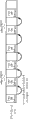
Subsequently, with reference to Figure 1A and Figure 1B, this technology is described.In Figure 1A and 1B, " i12 " represents I picture; " p02 ", " p03 " ... represent P picture; And " b00 ", " b01 " ... represent B picture.Row and the row below above of each of Figure 1A and Figure 1B represent respectively (for example) even field and odd field.
Therefore,, when coding video frequency data, forbid that picture p13 and p16 are used the picture p03 belonging to early than the GOP 0 of GOP 1 as reference pictures.On the contrary, the picture i12 of p13 and p16 usage data GOP 1 is as reference pictures.Therefore, when arbitrary access GOP 1, predictive picture p13 and p16 from the picture i12 as reference pictures.Therefore, can decoded picture p17 picture afterwards.
Similarly, in Figure 1B, with two immediate reference pictures, belong to the picture p15 of GOP 1 and belong to the picture p03 early than the GOP 0 of GOP 1, carrying out the picture p18 of coded data GOP 1.When arbitrary access GOP 1, from picture i12, reproduce.Because picture p15 can not be with reference to the picture p03 for reference pictures, therefore can not decoded picture p15.Similarly, can not decode and use picture p03 and p15 as the picture p18. of reference pictures
In this case, when encoded video streams, forbid that picture p15 and p18 are used the picture p03 belonging to early than the GOP 0 of GOP1 as reference pictures.Picture p15 and p18 are used the picture i12 that belongs to GOP 1 as reference pictures.Therefore, when arbitrary access GOP 1, predictive picture p15 and p18 from the i12 as reference pictures.As a result, can decoded picture p18.
In above-mentioned EP_map, the position of the I picture of video flowing is used as to inlet point.In MPEG2 video, there is not such predictive mode: be subordinated to the picture that prediction in the picture of the GOP that is later than the current GOP in DISPLAY ORDER is later than the I picture that belongs to current GOP in DISPLAY ORDER.Therefore,, when when using I picture as inlet point, guarantee from I picture access randomly and reproduce current GOP.
But in recent years, ISO (International Standards Organization) has carried out International standardization by moving picture compressing and coding system MPEG-4AVC|H.264.MPEG-4AVC|H.264 system realizes higher code efficiency and compression ratio than the traditional coded system such as MPEG2 and MPEG4 system.In addition, MPEG-4AVC|H.264 system usage data is realized high transmission efficiency by a plurality of transfer channels of its transmission.Therefore, MPEG-4AVC|H.264 can transmit video flowing by the degree of freedom higher than prior art systems.
Because MPEG-4AVC|H.264 system can have a plurality of reference pictures, so it can be with reference to the picture in a plurality of past.For example, in MPEG-4AVC|H.264, can in the P picture more Zao from the I picture than DISPLAY ORDER, predict the P picture that is later than I picture.
Therefore, in the prior art, when by by all if when being recorded to recording medium and then reproducing from it with reference to the encoded video flowing of coded system of MPEG-4AVC|H.264 system of a plurality of pictures and so on, if I picture is recorded in EP_map as random access position (inlet point), do not guarantee by arbitrary access the picture that reproduces conventionally with I picture, do not start.
Summary of the invention
Therefore, the object of this aspect is to provide data recording equipment, method and program, data reproducing equipment, method and program, recording medium and data structure, it is encoded during with recorded video stream that their allow in the picture of the reference pictures with from as early than the I picture DISPLAY ORDER prediction to be later than the predictive mode of picture of the I picture in DISPLAY ORDER, the video flowing that arbitrary access is reproduced from recording medium.
A first aspect of the present invention is to provide a kind of data recording equipment, the video flowing of encoding by the either method in the 1st coding method and the 2nd coding method to recording medium recording, wherein, the 1st coding method is encoded to video flowing, take from the image that can independently decode is unit to the set next image that can independently the decode image nearby following on decoding order, can be by the image in this unit, predict in this unit, following image in the above-mentioned image that can independently decode on DISPLAY ORDER; The 2nd coding method is encoded to video flowing, take from the image that can independently decode is unit to the set next image that can independently the decode image nearby following on decoding order, can compare the image in unit in the past by Yu Gai unit, predict in this unit, following image in the above-mentioned image that can independently decode on DISPLAY ORDER; It is characterized in that, notebook data tape deck has: code device, by above-mentioned the 2nd coding method, video flowing is encoded and generated numeralization video flowing, wherein, take from the image that can independently decode is unit to the set next image that can independently the decode image nearby following on decoding order, is constrained to and forbids that the image that Cong Yugai unit compares in unit in the past predicts that the DISPLAY ORDER of comparing with the above-mentioned image that can independently decode in Gai unit is following image; Form generating apparatus, carries out the positional information on the recovery time information on the above-mentioned numeralization video flowing of the above-mentioned image that can independently decode and this numeralization video flowing correspondence and generates form; Tape deck, carries out correspondence by the above-mentioned numeralization video flowing of encoding by above-mentioned code device and the above table that generates by above table generating apparatus and is recorded in recording medium.
A second aspect of the present invention is to provide a kind of data record method, the video flowing of encoding by the either method in the 1st coding method and the 2nd coding method to recording medium recording, wherein, the 1st coding method is encoded to video flowing, take from the image that can independently decode is unit to the set next image that can independently the decode image nearby following on decoding order, can be by the image in this unit, predict in this unit, following image in the above-mentioned image that can independently decode on DISPLAY ORDER; The 2nd coding method is encoded to video flowing, take from the image that can independently decode is unit to the set next image that can independently the decode image nearby following on decoding order, can compare the image in unit in the past by Yu Gai unit, predict in this unit, following image in the above-mentioned image that can independently decode on DISPLAY ORDER; It is characterized in that, this data record method has following steps: coding step, by above-mentioned the 2nd coding method, video flowing is encoded, and generate numeralization video flowing, wherein, take from the image that can independently decode is unit to the set next image that can independently the decode image nearby following on decoding order, is constrained to and forbids that the DISPLAY ORDER of comparing with the above-mentioned image that can independently decode that Cong Yugai unit is in a ratio of in the image prediction Gai unit in unit is in the past following image; Form generates step, and the positional information on the recovery time information on the above-mentioned numeralization video flowing of the above-mentioned image that can independently decode and this numeralization video flowing is carried out to correspondence and generated form; Recording step, by the numeralization video flowing at above-mentioned coding step coding with generate at above table the above table that step generates and carry out correspondence and be recorded in recording medium.
The third aspect of this aspect is to provide a kind of data recording program, make computer installation carry out the data record method of the video flowing of encoding by the either method in the 1st coding method and the 2nd coding method to recording medium recording, wherein, the 1st coding method is encoded to video flowing, take from the image that can independently decode is unit to the set next image that can independently the decode image nearby following on decoding order, can be by the image in this unit, predict in this unit, following image in the above-mentioned image that can independently decode on DISPLAY ORDER, the 2nd coding method is encoded to video flowing, take from the image that can independently decode is unit to the set next image that can independently the decode image nearby following on decoding order, can compare the image in unit in the past by Yu Gai unit, predict in this unit, following image in the above-mentioned image that can independently decode on DISPLAY ORDER, it is characterized in that, above-mentioned data record method has following steps: coding step, by above-mentioned the 2nd coding method, video flowing is encoded, and generate numeralization video flowing, wherein, take from the image that can independently decode is unit to the set next image that can independently the decode image nearby following on decoding order, is constrained to and forbids that the DISPLAY ORDER of comparing with the above-mentioned image that can independently decode that Cong Yugai unit compares in the image prediction Gai unit in unit is in the past following image, form generates step, and the positional information on the recovery time information on the above-mentioned numeralization video flowing of the above-mentioned image that can independently decode and this numeralization video flowing is carried out to correspondence and generated form, recording step, by the above-mentioned numeralization video flowing of encoding by above-mentioned coding step with generate by above table above table that step generates and carry out correspondence and be recorded in recording medium.
A fourth aspect of the present invention is to provide a kind of data reproducing device, the video flowing of encoding by the either method in the 1st coding method and the 2nd coding method to recording medium reproducing, wherein, the 1st coding method is encoded to video flowing, take from the image that can independently decode is unit to the set next image that can independently the decode image nearby following on decoding order, can be by the image in this unit, predict in this unit, following image in the above-mentioned image that can independently decode on DISPLAY ORDER, the 2nd coding method is encoded to video flowing, take from the image that can independently decode is unit to the set next image that can independently the decode image nearby following on decoding order, can compare the image in unit in the past by Yu Gai unit, predict in this unit, following image in the above-mentioned image that can independently decode on DISPLAY ORDER, it is characterized in that, notebook data transcriber has: transcriber, its reproducing recorded medium, this recording medium recording the numeralization video flowing of video flowing being encoded and generate by above-mentioned the 2nd coding method, and the positional information on the recovery time information on the above-mentioned numeralization video flowing of the above-mentioned image that can independently decode and this numeralization video flowing is carried out to correspondence and the form that generates, wherein, the above-mentioned coding that should carry out video flowing by above-mentioned the 2nd coding method is, take from the image that can independently decode is unit to the set next image that can independently the decode image nearby following on decoding order, be constrained to and forbid that Cong Yugai unit compares comparing with the above-mentioned image that can independently decode on DISPLAY ORDER in the image prediction Gai unit in unit in the past and carries out for following image, decoding controller, control, make according to the above table being reproduced by above-mentioned transcriber, the position of take by the represented above-mentioned numeralization video flowing of above-mentioned positional information is starting point, carry out the decoding of the above-mentioned numeralization video flowing that reproduced by above-mentioned transcriber, wherein, the corresponding above-mentioned recovery time information of above-mentioned positional information.
A fifth aspect of the present invention is to provide a kind of data reproducing method, the video flowing of encoding by the either method in the 1st coding method and the 2nd coding method to recording medium reproducing, wherein, the 1st coding method is encoded to video flowing, take from the image that can independently decode is unit to the set next image that can independently the decode image nearby following on decoding order, can be by the image in this unit, predict in this unit, following image in the above-mentioned image that can independently decode on DISPLAY ORDER, the 2nd coding method is encoded to video flowing, take from the image that can independently decode is unit to the set next image that can independently the decode image nearby following on decoding order, can compare the image in unit in the past by Yu Gai unit, predict in this unit, following image in the above-mentioned image that can independently decode on DISPLAY ORDER, it is characterized in that, notebook data reproducting method has: reproduce step, its reproducing recorded medium, this recording medium recording the numeralization video flowing of video flowing being encoded and generate by above-mentioned the 2nd coding method, and the positional information on the recovery time information on the above-mentioned numeralization video flowing of the above-mentioned image that can independently decode and this numeralization video flowing is carried out to correspondence and the form that generates, wherein, the above-mentioned coding that should carry out video flowing by above-mentioned the 2nd coding method is, take from the image that can independently decode is unit to the set next image that can independently the decode image nearby following on decoding order, be constrained to and forbid that Cong Yugai unit compares comparing with the above-mentioned image that can independently decode on DISPLAY ORDER in the image prediction Gai unit in unit in the past and carries out for following image, step is controlled in decoding, control, make according to the above table being reproduced by above-mentioned reproduction step, the position of take by the represented above-mentioned numeralization video flowing of above-mentioned positional information is starting point, carry out the decoding of the above-mentioned numeralization video flowing to being reproduced by above-mentioned reproduction step, wherein, the corresponding above-mentioned recovery time information of above-mentioned positional information.
The 6th aspect of this aspect is to provide a kind of data reproduction program, make computer installation carry out the data reproducing method of the video flowing of encoding by the either method in the 1st coding method and the 2nd coding method to recording medium reproducing, wherein, the 1st coding method is encoded to video flowing, take from the image that can independently decode is unit to the set next image that can independently the decode image nearby following on decoding order, can be by the image in this unit, predict in this unit, following image in the above-mentioned image that can independently decode on DISPLAY ORDER, the 2nd coding method is encoded to video flowing, take from the image that can independently decode is unit to the set next image that can independently the decode image nearby following on decoding order, can compare the image in unit in the past by Yu Gai unit, predict in this unit, following image in the above-mentioned image that can independently decode on DISPLAY ORDER, it is characterized in that, above-mentioned data reproducing method has: reproduce step, its reproducing recorded medium, this recording medium recording the numeralization video flowing of video flowing being encoded and generate by above-mentioned the 2nd coding method, and the positional information on the recovery time information on the above-mentioned numeralization video flowing of the above-mentioned image that can independently decode and this numeralization video flowing is carried out to correspondence and the form that generates, wherein, the above-mentioned coding that should carry out video flowing by above-mentioned the 2nd coding method is, take from the image that can independently decode is unit to the set next image that can independently the decode image nearby following on decoding order, be constrained to and forbid that Cong Yugai unit compares comparing with the above-mentioned image that can independently decode on DISPLAY ORDER in the image prediction Gai unit in unit in the past and carries out for following image, step is controlled in decoding, control, make according to the above table being reproduced by above-mentioned reproduction step, the position of take by the represented above-mentioned numeralization video flowing of above-mentioned positional information is starting point, carry out the decoding by the above-mentioned numeralization video flowing of above-mentioned reproduction step reproduction, wherein, the corresponding above-mentioned recovery time information of above-mentioned positional information.
According to of the present invention first, second and the third aspect, according to predictive coding method encoded video streams and by coded videograph in the data record method of recording medium, being encoded as one of them unit is to start with independent decodable code picture as the video flowing of a plurality of unit of active cell, the picture group finishing with the picture early than belonging to the independent decodable code picture of the unit that active cell in ratio decoder order is more late, in predictive coding method, be subordinated to early than prediction in the picture of the unit of active cell than the more late picture of independent decodable code picture that belongs to active cell in DISPLAY ORDER.To forbid the mode encoded video streams of predictive coding method and to produce the video flowing of encoding, being encoded as one of them unit is the picture group that starts, finishes with the picture early than belonging to the independent decodable code picture of the unit that active cell in ratio decoder order is more late with independent decodable code picture as the video flowing of a plurality of unit of active cell, in predictive coding method, be subordinated to early than prediction in the picture of the unit of active cell than the more late picture of independent decodable code picture that belongs to active cell in DISPLAY ORDER.Establishment is by the table that in the video flowing of coding, independently the positional information in the recovery time information of decodable code picture and the video flowing of coding is associated.Coded video flowing is associated with created table.By associated video flowing and table record on recording medium.Therefore, when rendering data from recording medium, by specifying the recovery time to guarantee the random access reproduction for the encoded video streams reproducing from this recording medium.
According to the present invention the 4th, the the 5th and the 6th aspect, from encoding thereon according to predictive coding method and having recorded rendering data the recording medium of video flowing, being encoded as one of them unit is to start with independent decodable code picture as the video flowing of a plurality of unit of active cell, the picture group finishing with the picture early than belonging to the independent decodable code picture of the unit that active cell in ratio decoder order is more late, in predictive coding method, be subordinated to early than prediction in the picture of the unit of active cell than the more late picture of independent decodable code picture that belongs to active cell in DISPLAY ORDER.From to forbid that the mode of predictive coding method encodes and produced rendering data the recording medium of video flowing thereon, being encoded as one of them unit is to start with independent decodable code picture as the video flowing of a plurality of unit of active cell, the picture group finishing with the picture early than belonging to the independent decodable code picture of the unit that active cell in ratio decoder order is more late, in predictive coding method, be subordinated to early than prediction in the picture of the unit of active cell than the more late picture of independent decodable code picture that belongs to active cell in DISPLAY ORDER, and recorded relatively the table that in the video flowing of coding, independently the positional information in the recovery time information of decodable code picture and the video flowing of coding is associated.The encoded video streams that the indicated position decoding of positional information corresponding to recovery time information according to reproduced table from the video flowing with coding reproduces.Therefore,, by specifying the recovery time, guarantee the random access reproduction of the encoded video streams for reproducing from this recording medium.
According to this aspect, have from data early than the picture of the GOP of current GOP prediction be later than in the video coding system of predictive mode of picture of the I picture that belongs to current GOP, to be subordinated to the forbidden mode of predictive mode that is later than the picture of the I picture that belongs to current GOP early than prediction in the picture of the GOP of current GOP, the AV that encodes stream.Establishment has the EP_map of the PTS of access unit, and to forbid the mode of predictive mode, the I picture of encoding or the IDR picture defining at MPEG 4AVC|H.264 start this access unit.EP_map and AV stream are recorded on recording medium.As a result, guarantee the random access reproduction that starts from the indicated inlet point of EP_map in AV stream.
Accompanying drawing explanation
Figure 1A and Figure 1B show according to prior art and are subordinated to the schematic diagram of predictive mode that is later than the picture of the I picture that belongs to current GOP early than prediction in the picture of the GOP of the current GOP in DISPLAY ORDER;
Fig. 2 shows the schematic diagram of the schematic configuration of the application format on the recording medium using in recording and reconstruction system according to the present invention;
Fig. 3 shows the schematic diagram in the schematic configuration flowing according to the AV recording on the recording medium using in the recording and reconstruction system of this aspect;
Fig. 4 shows the schematic diagram of the example of the shearing Segment A V stream of describing EP_map;
Fig. 5 shows the schematic diagram of the concept example of E_ map;
Fig. 6 A, Fig. 6 B and Fig. 6 C show the schematic diagram of the access unit can random-access I picture to start;
Fig. 7 shows the schematic diagram of example of data structure of the source grouping of field SPN_EP_start indication;
Fig. 8 shows the schematic diagram of describing EP_map in further detail;
Fig. 9 shows the schematic diagram of describing EP_map in further detail;
Figure 10 shows the schematic diagram of describing EP_map in further detail;
Figure 11 shows the schematic diagram of the example of the grammer of showing EP_map_for_one_stream_PID ();
Figure 12 shows the schematic diagram of example of the grammer of piece EP_map_for_one_stream_PID;
Figure 13 shows the flow chart of the example of the process that creates EP_map;
Figure 14 A and Figure 14 B show the schematic diagram of describing the situation that video PID changes in transport stream;
Figure 15 shows in the situation that carry out the block diagram for the example of the player model of the search of I picture or IDR picture;
Figure 16 shows the flow chart of the example of the process of I picture search in player model; With
Figure 17 A and Figure 17 B show the block diagram of example of the structure of motion picture recording and reconstruction equipment according to the embodiment of the present invention.
Embodiment
Embodiments of the present invention will be described below.Fig. 2 shows the schematic configuration of the application format on the recording medium using in recording and reconstruction system according to the present invention.This form has two-layer, with PlayList and the Clip of its management AV stream.
The antithetical phrase of an AV stream and additional information thereof is used as to an object and is called shearing fragment.The AV stream file that comprises AV stream is called and shears Segment A V stream file, thereby the file that comprises corresponding additional information is called to shearing clip information file.
On time shaft, to shearing the content of Segment A V stream file, shine upon.The timestamp corresponding by the access point with shearing fragment carrys out given playlist.When the access point of the shearing fragment of the free stamp of playlist index strip, by shearing clip information file, find to indicate the address information of the decoding start address of this stream.
Playlist is the reproduction regions group of shearing fragment.A reproduction regions is called to playitems playitem (PlayItem).Playitems playitem is the antithetical phrase that on time shaft, IN point and OUT are ordered.Therefore, playlist is playitems playitem group.
With volume information, manage all playlists that record and shear fragment on a dish.
Fig. 3 shows the schematic configuration of the AV stream recording on the recording medium using in recording and reconstruction system according to the present invention.According to the present invention, BDAV (Blu-ray disc audio/video) the MPEG2 transport stream using AV stream on recording medium is treated.BDAV MPEG2 transport stream is comprised of an integer unit (aligned unit) of aiming at 6144 byte-sized.
The unit of an aligning is comprised of 32 sources.Source grouping has the size of 192 bytes.The grouping of source is comprised of the transmission that has the transmission grouping additional headers (TP_extra header) of four byte-sized and have 188 byte-sized.
The data that include video flowing and audio stream in MPEG2PES (Basic Flow of packetizing).In other words, the data of video flowing and audio stream suitably cut apart and be grouped in the data division of each PES grouping.By comprising the PES packet header that flows ID, add in PES grouped data part the type of the Basic Flow that this stream ID sign is transmitted by current PE S grouping to.Form by this way PES grouping.
By PES packet switched, it is transmission grouping.In other words, to transmit the size of the Payload of grouping, cut apart PES grouping.In a predetermined manner transfer of packet header is added in Payload.As a result, form transmission grouping.Transfer of packet header comprises the PID (packet ID) as the identification information of the data that comprise for Payload.
The source packet numbers starting with 0 (for shearing the beginning of Segment A V stream) and increase is one by one distributed to source grouping.The unit of aiming at starts with the first byte of source grouping.
Above-mentioned shearing clip information file comprises EP_map.As in the above, as described in " background technology " part, when timestamp being distributed to the access point of shearing fragment, with EP_map, find from it, to start the data address that data read in shearing Segment A V stream file.EP_map is the list of the inlet point (EP) that extracts from Basic Flow and transport stream.EP_map has for finding at AV stream the address information that starts the inlet point of decoding from it.An EP entry of EP_map is comprised of the antithetical phrase of the data address of presentative time stamp (PTS) and access unit corresponding to the PTS in AV stream.In MPEG-4AVC|H.264 system, an access unit is corresponding with a picture.
Subsequently, with reference to Fig. 4 and Fig. 5, EP_map is described.Fig. 4 shows for describing the example of the shearing Segment A V stream of EP_map.In the example of Fig. 4, shear Segment A V stream and formed by three multiplexing video flowings.The PID (group character) comprising in the header of the transmission grouping of being divided into groups by each source identifies each video flowing.In the example shown in Fig. 4, three video flowings that identified are multiplexed into one shear in Segment A V stream by PID=x, PID=y and PID=z.
At each video flowing of the position of I picture access randomly.In Fig. 4, respectively with blacking pattern, hatching pattern and intersection (" X ") hatching pattern identify the beginning byte that comprises I picture three video flowings, by the source of box indicating, divided into groups.There is no blacking or add the source grouping that other box indicatings of shade comprise the video data that is not random access point and the source grouping that comprises other video datas.
For example, in the video flowing identifying at PID=x, the source grouping that comprises beginning byte that can random-access I picture and have a source packet numbers X1 is placed on to the position of PTS=pts (x1) on the time shaft of shearing Segment A V stream.Similarly, in identical video flowing, the source grouping that comprises beginning byte that can random-access I picture and have a source packet numbers X2 is placed on to the position of PTS=pts on time shaft (x2).
Fig. 5 shows the concept example that flows corresponding EP_map with the shearing Segment A V shown in Fig. 4.In the example shown in Fig. 5, EP_map has the data of field stream_PID, entry PTS_EP_start and entry SPN_EP_start.Field stream_PID comprises the PID that transmits the transmission grouping of video flowing with it.The PTS that entry PTS_EP_start comprises the access unit (will be described later) can random-access I picture to start.The address of the source grouping of the first byte of the access unit that entry SPN_EP_start comprises the value institute reference that comprises the entry PTS_EP_start in AV flows.
With reference to the example shown in Fig. 4, in EP_map, the PID of each video flowing is stored in field stream_PID.For field stream_PID, create entry PTS_EP_start and entry SPN_EP_start are carried out to associated table EP_map_for_one_stream_PID ().For example, in Fig. 5, the video flowing identifying for PID=x, table EP_map_for_one_stream_PID[0] associated PTS=pts (x1) and source packet numbers X1; PTS=pts (x2) and source packet numbers X2; ...; And PTS=pts (xk) and source packet numbers Xk.For other PID, identify and each multiplexing video flowing creates this table.In flowing corresponding shearing clip information file with shearing Segment A V, comprise EP_map.
Fig. 6 A, 6B and 6C show the schematic diagram of the access unit can random-access I picture to start.In Fig. 6 A, Fig. 6 B and Fig. 6 C, box indicating picture.By the indicated picture of the arrow of " inlet point ", represent the access unit can random-access I picture to start.Fig. 6 A and Fig. 6 B show defined IDR picture in MPEG-4AVC|H.264.In MPEG-4AVC|H.264 system, forbid predicting the picture that is later than the IDR picture in decoding order from the picture of the IDR picture early than decoding order.
In MPEG-4AVC|H.264, serial access unit is called to " sequence ".Each sequence of can decoding independently.Sequence need to start with IDR picture.For each IDR picture, buffer is resetted.In addition forbid from be later than the picture of the IDR picture decoding order with reference to the picture early than the IDR picture in decoding order.Therefore, can be from starting to decode independently each sequence.
In the example shown in Fig. 6 A, when encoded video streams, forbid predicting the picture p10 that is later than IDR picture in decoding order from the picture p12 early than IDR picture decoding order.In the example shown in Fig. 6 B, suppose to decode at the picture on " after the border of GOP " with the order of IDR picture, picture b10, picture p13 and picture b12.At this some place, because picture b10 is later than IDR picture on decoding order, so when video flowing is encoded, forbid predictive picture p10 from the picture p02 early than IDR picture.Similarly, in Fig. 6 B, forbid predictive picture p13 from picture p02.
Fig. 6 C shows the example that replaces the IDR picture shown in Fig. 6 B with I picture (picture i11).In this case, when video flowing is encoded, forbid being subordinated to the picture that is later than the picture i11 that belongs to current GOP in DISPLAY ORDER early than prediction in the picture of the GOP of the current GOP in DISPLAY ORDER.In the example shown in Fig. 6 C, when video flowing is encoded, forbid predictive picture p13 from picture p02.
MPEG-4AVC|H.264 system does not resemble MPEG2 system and defines clearly GOP.According to the embodiment of the present invention, for the convenient picture group that the IDR picture with in decoding order and I picture are started is called GOP.MPEG-4AVC|H.264 system allows a plurality of interframe encode type hybrid such as I fragment, P fragment and B fragment in a picture.According to this execution mode of the present invention, I picture represents only to comprise the picture of I fragment.
Fig. 7 shows the example of the data structure of the indicated source grouping of field SPN_EP_start.As mentioned above, by the header TP_extra_header with four byte-sized being added to composition source in the transmission grouping with 188 byte-sized, divide into groups.Transmission packet partial is partly comprised of header portion (TP header) and Payload.The source packet numbers that field SPN_EP_start comprises source grouping, as shown in Fig. 6 A, 6B and 6C, the first byte that this source grouping comprises the access unit starting with IDR picture or I picture.In MPEG-4AVC|H.264 system, access unit, picture, starts with AU delimiter (delimiter) (access unit delimiter).Be followed by SRS (sequential parameter group) and PPS (frame parameter group) after AU delimiter, be followed by afterwards the beginning of fragment data of IDR picture described in Fig. 6 A, Fig. 6 B and Fig. 6 C or I picture or whole.
When the value of the mark payload_unit_start_indicator of the header (TP header) of transmission grouping be " 1 ", its Payload of indicating new PES to divide into groups to transmit grouping starts, and access unit is with source grouping beginning.
Below with reference to Fig. 8, Fig. 9 and Figure 10, EP_map is described in further detail.Routine as shown in Figure 8, table EP_map_for_one_stream_PID () is comprised of two sublist EP_coarse and EP_fine.Sublist EP_coarse is the table for searching for rough unit, and sublist EP_fine is the table for searching for meticulous unit.Because EP_map is comprised of these two tables, thus can reduce to show the size of data of EP_map_for_one_stream_PID (), and the performance of data search is provided.
In the example shown in Fig. 8, sublist EP_fine carries out associated table by entry PTS_EP_fine with entry SPN_EP_fine.In this sublist, with ascending order, take and start entry number to distribute to entry as 0 for going up most entry.In sublist EP_fine, the data width of entry PTS_EP_fine and entry SPN_EP_fine is four bytes altogether.On the contrary, sublist EP_coarse carries out associated table by entry ref_to_EP_fine_id, entry PTS_EP_coarse with entry SPN_EP_coarse.The data width of entry ref_to_EP_fine_id, entry PTS_EP_coarse and entry SPN_EP_coarse is eight bytes altogether.The number of entries Nf of sublist EP_fine is less than the number of entries Nc of sublist EP_coarse.
The entry of sublist EP_fine is comprised of the bit information in each LSB (minimum effective bit) side of the entry PTS_EP_start of EP_map and entry SPN_EP_start.Bit information in each MSB (the highest significant bit) side of the entry of sublist EP_coarse entry PTS_EP_start and entry SPN_EP_start and corresponding entry number in sublist EP_fine forms.This entry number is the entry of sublist EP_fine, has the bit information in LSB mono-side, from identical data PTS_EP_start, extracts.
Fig. 9 shows the example of the form of entry PTS_EP_coarse and entry PTS_EP_fine.PTS, i.e. entry PTS_EP_start, has the data length of 32 bits.When MSB is the 32nd bit and LSB while being the 0th bit, in the example shown in Fig. 9, for the entry PTS_EP_coarse for searching for rough unit, use 14 bits from the 32nd bit to the 19 bits of PTS_EP_start.Rely on entry PTS_EP_coarse, can carry out resolution and be the search of maximum 26.5 hours of 5.8 seconds.For the entry PTS_EP_fine for searching for meticulous unit, use 11 bits from the 19th bit to the 9 bits.Rely on entry PTS_EP_fine, can carry out 5.7 milliseconds of maximum search of 11.5 seconds of resolution.Common the 19th bit that uses of entry PTS_EP_coarse and entry PTS_EP_fine.Do not use nine bits from the 0th bit to the 8 bits in LSB mono-side.
Figure 10 shows the example of the form of entry SPN_EP_coarse and entry SPN_EP_fine.Source packet numbers, i.e. SPN_EP_start, has the data length of 32 bits.When MSB is the 31st bit and LSB while being the 0th bit, in the example shown in Figure 10, for the entry SPN_EP_coarse for searching for rough unit, use entry SPN_EP_start from all bits of the 31st bit to the 0 bit.On the contrary, for the entry SPN_EP_fine for searching for meticulous unit, use entry SPN_EP_start from the 16th 17 bits to the 0th bit.Rely on entry SPN_EP_fine, can search for the AV stream file of at most about 25MB (Mbytes).
For source packet numbers, can be by the value of the predetermined number of bits in MSB mono-side as entry SPN_EP_coarse.For example, for entry SPN_EP_coarse, use 17 bits from the 31st bit to the 16 bits of entry SPN_EP_start.For entry SPN_EP_fine, use 17 bits from the 16th bit to the 0 bit of entry SPN_EP_start.
Figure 11 shows the example of the grammer of table EP_map_for_one_stream_PID ().In this example, using and describe grammer as the C language of the program description language for computer equipment etc.This is also applicable to illustrate other accompanying drawings of other grammers.
Table EP_map_for_one_stream_PID () forms piece EP_map ().Field number_of_stream_PID_entries represents the number of entries of the table EP_map_for_one_stream_PID of EP_map.The independent variable that relies on value [k], by the number of times of the value representation of the content Repeating Field number_of_stream_PID_entries of for circulation.Field stream_PID[k] represent the value of the PID of transmission grouping, this grouping transmission is by the Basic Flow of table EP_map_for_one_stream_PID (being called [k] individual table EP_map_for_one_stream_PID below) institute's reference of [k] the individual entry as EP_map.Field EP_stream_type[k] represent the type by the Basic Flow of [k] individual EP_map_for_one_stream_PID institute reference.Field num_EP_coarse_entries[k] be illustrated in the number of entries of the sublist EP_coarse in [k] individual table EP_map_for_one_stream_PID.Field num_EP_fine_entries[k] be illustrated in the number of entries of the sublist EP_fine in [k] individual table EP_map_for_one_stream_PID.Field EP_map_for_one_stream_PID_start_address[k] represent the relative byte location that [k] individual EP_map_for_one_stream_PID starts in piece EP_map ().This value of byte number representation being started by the first byte with piece EP_map ().
After for circulation, be followed by filling word.After filling word, description block EP_map_for_one_stream_PID.Piece EP_map_for_one_stream_PID is the EP_map for a stream of a plurality of AV stream that is multiplexed to transport stream as shown in Figures 4 and 5.
Figure 12 shows the example of the grammer of piece EP_map_for_one_stream_PID.In order to explain the semanteme of piece EP_map_for_one_stream_PID, will the entry PTS_EP_start of entry and the connotation of entry SPN_EP_start in the source of the data of storing be described in piece EP_map_for_one_stream_PID.Entry SPN_EP_start is associated with PTS_EP_start, and SPN_EP_start represents the inlet point of AV stream.Entry PTS_EP_coarse is associated with entry PTS_EP_fine, and obtains entry PTS_EP_fine from identical entry PTS_EP_start.Similarly, SPN_EP_coarse is associated with entry SPN_EP_fine, and obtains SPN_EP_fine from same item SPN_EP_start.
PTS_EP_start and SPN_EP_start are defined as follows.
As shown in Figure 9, entry PTS_EP_start is the signless integer with 33 Bit data length.The entry PTS_EP_start with 33 bit lengths represents the PTS of video access units, and this video access units starts with the I picture of the IDR picture as shown in Fig. 6 A, Fig. 6 B and Fig. 6 C or AV stream.
As shown in Figure 10, entry SPN_EP_start is the signless integer with 32 bit lengths.Entry SPN_EP_start is illustrated in the address that AV flows the source grouping of the first byte that comprises the video access units being associated with entry PTS_EP_start.Entry SPN_EP_start is represented by the source packet numbers of counting (increase), dividing into groups in first source of flowing from AV with initial value " 0 ".
Subsequently by the semanteme of description block EP_map_for_one_stream_PID.As shown in Figure 12, piece EP_map_for_one_stream_PID is comprised of a for circulation and the 2nd for circulation, the one for looping discription is for carrying out the sublist EP_coarse of rough unit searches, and the 2nd for looping discription is for carrying out the sublist EP_fine of meticulous unit searches according to the Search Results of a for circulation.Before the first and second for circulations, there is field EP_fine_table_start_address.Field EP_fine_table_start_address is by the field EP_video_type[EP_fine_id of the 2nd for circulation] the start address of the first byte, be expressed as the relative byte number starting from the first byte of piece EP_map_for_one_stream_PID.Byte number starts with value " 0 " relatively.
To be cycled to repeat with a for of independent variable [i] the represented number of times of number of entries Nc of sublist EP_coarse.In a for circulation, field ref_to_EP_fine_id[i] represent to have with before by field ref_to_EP_fine_id[i] field PTS_EP_coarse[i] number of entries of sublist EP_fine of the entry PTS_EP_fine that is associated of indicated entry PTS_EP_coarse.From same item PTS_EP_start, obtain entry PTS_EP_fine and the entry PTS_EP_coarse that is associated with it.The value of the independent variable [EP_fine_id] sequentially defining with appearance in circulating by the 2nd for provides field ref_to_EP_fine_id[i].
After the one for circulation, be followed by filling word, be followed by afterwards the 2nd for circulation.To be cycled to repeat with the 2nd for of independent variable [EP_fine_id] the represented number of times of line number amount Nf of sublist EP_fine.In the 2nd for circulation, field EP_video_type[EP_fine_id has been described], field I_end_position_offset[EP_fine_id], field PTS_EP_fine[EP_fine_id] and field SPN_EP_fine[EP_fine_id].Field PTS_EP_fine[EP_fine_id] and field SPN_EP_fine[EP_fine_id] storage from sublist EP_fine with entry PTS_EP_fine and the entry SPN_EP_fine of independent variable [EP_fine_id] institute reference.
Following entry PTS_EP_coarse, entry PTS_EP_fine, entry SPN_EP_coarse and the entry SPN_EP_fine of obtaining.Suppose Nf entry of the value that the ascending order of the data SPN_EP_start that sublist EP_fine comprises to be associated is arranged.According to formula (1), from corresponding entry PTS_EP_start, obtain entry PTS_EP_fine.
PTS_EP_fine[EP_fine_id]=(PTS_EP_start[EP_fine_id]>>9)/211.....(1)
By formula (2) and (3), represent the relation between entry PTS_EP_coarse and corresponding entry PTS_EP_fine.
PTS_EP_coarse[i]=(PTS_EP_start[ref_to_EP_fine_id[i]]>>19)/214....(2)
PTS_EP_fine[ref_to_EP_fine_id[i]]=
(PTS_EP_start[ref_to_EP_fine_id[i]]>>9)/211....(3)
According to formula (4), from corresponding entry SPN_EP_start, obtain entry SPN_EP_fine.
SPN_EP_fine[EP_fine_id]=SPN_EP_start[EP_fine_id]/217....(4)
By formula (5) and (6), represent the relation between entry SPN_EP_coarse and corresponding entry SPN_EP_fine.
SPN_EP_coarse[i]=SPN_EP_start[ref_to_EP_fine_id[i]]....(5)
SPN_EP_fine[ref_to_EP_fine_id[i]]=SPN_EP_start[ref_to_EP_fine_id[i]]/217....(6)
Formula (1) is in (6) in the above, and the bit that surpasses x bit in the LSB of data mono-side is used in symbol " > > x " indication.
Subsequently, with reference to the flow chart shown in Figure 13, the process that creates above-mentioned EP_map is described.By the multiplex stream analysis part 25 of describing in the back with reference to Figure 17 A and Figure 17 B, carried out the process shown in the flow chart of Figure 13.When the AV stream as having the transport stream of form with reference to Figure 2 and 3 as described and inputting is recorded on recording medium, the process shown in flowchart.
Input transport stream is input in multiplex stream analysis part 25.At step S10, start to create the process of EP_map.At step S11, multiplex stream analysis part 25 is analyzed input transport stream, and is that the video flowing that recorded shearing Segment A V flows is specified PID.When input transport stream packets is when having a plurality of video flowing of different PID, multiplex stream analysis part 25 is that the video flowing of recorded shearing Segment A V stream is specified PID.At step S12, multiplex stream analysis part 25 selection from input transport stream has the transmission of the video flowing of specified PID and divides into groups and receive this grouping.
At step S13, multiplex stream analysis part 25 determines that the first the byte whether Payload of the transmission grouping receiving divides into groups with PES starts.Can be undertaken this by the value of the sign payload_unit_start_indicator of transfer of packet header determines.When this value is " 1 ", the Payload of indication transmission grouping starts with the first byte of PES grouping.When the Payload of determined result indication transmission grouping does not start with the first byte of PES byte, flow process turns back to step S12.
When the first byte that the Payload dividing into groups when the determined result indication of step S13 transmission divides into groups with PES starts, flow process advances to step S14.At step S14, whether the data division that multiplex stream analysis part 25 is determined PES grouping is to use the first byte of the video access units starting with reference to Fig. 6 A, 6B and the described IDR picture of 6C or I picture to start.By checking that carrying out this with reference to the described access unit delimiter SPS comprising continuously in transmission grouping of Fig. 7 and PPS determines.When determined result indication PES grouped data part does not start with the first byte of video access units, flow process turns back to step S12.
When the PES grouped data part of the determined result indication PES of step S14 grouping starts with the first byte of the video access units that starts with IDR picture or I picture, flow process advances to step S15.At step S15, multiplex stream analysis part 25 current transmission is divided into groups (be source grouping) be appointed as inlet point.
At step S16, multiplex stream analysis part 25 obtains packet numbers (source packet numbers), the IDR picture comprising in this grouping or the PTS of I picture and the PID of the video flowing that inlet point belongs to that is designated as the transmission grouping (source grouping) of inlet point at step S15.Obtained information is provided to control section from multiplex stream analysis part 25.Control section creates EP_map according to received information.
As long as just by packet numbers being counted to obtain the packet numbers of the transmission grouping that is designated as inlet point, the packet numbers of the transport stream that comprises the first byte of shearing Segment A V stream file is " 0 " when step S12 receives the transmission grouping of video flowing.The PTS of IDR picture and I picture is included in the header portion of PES grouping.
At step S17, multiplex stream analysis part 25 determines whether the transmission grouping of current input is last input transmission grouping.When current the inputted transmission grouping of determined result indication is the transmission grouping of last input, process completes.When current the inputted transmission grouping of determined result indication is not last transmission grouping, flow process turns back to step S12.
Situation about subsequently, description video PID being changed in transport stream.In this case, example as shown in Figure 14 A, EP_map preferably comprises EP_map as the sublist for each video PID.Example as shown in Figure 14 B, will consider to change at the video PID=x in half above that shears Segment A V stream file the situation of video PID=y in the later half of shearing Segment A V stream file.
In this case, example as shown in Figure 14 A, the EP_map of the shearing clip information file corresponding with shearing Segment A V stream file comprises the EP_map corresponding with the transmission grouping (source grouping) with video PID=x and divides into groups corresponding EP_map as sublist with the transmission with video PID=y.The PTS_EP_start entry of the EP_map corresponding with video PID=x and with the PTS_EP_start entry of EP_map corresponding to video PID=y be the value in reproducing sequence on same time axle.Therefore, if Figure 14 B is exemplified, when carrying out that search is reproduced etc., reproduction sequence that can be corresponding with the PTS_EP_start entry of the sublist with EP_map is come access continuously to have the source grouping of video PID=x and is had IDR picture or the I picture of video PID=y.
Subsequently, by the search operation of describing I picture and IDR picture.Figure 15 is illustrated in the example carrying out the player model in the situation of the search of I picture or IDR picture.In the following description, for convenient, will the search of I picture or IDR picture be called to the search of I picture.Figure 16 shows the example of the process of I picture search in the player model shown in Figure 15.
In Figure 15, player model has driver 100, file system 101, console controller 102, demodulation multiplexer 103 and decoder 104.By for example CPU (CPU), form console controller 102.Can come composing document system 101, demodulation multiplexer 103 and decoder 104 by software or the hardware of the upper operation of this CPU.User interface (UI) (not shown) notifies user's order to console controller.
Using for example CD and so on, on it, recorded and to have sheared Segment A V stream file and be loaded in driver 100 as the recording medium of transport stream.At step S20, file system 101 is rendering data from be loaded into the dish of driver 100, reads shearing clip information file, and the data of the EP_map of message file are sent to console controller 102 from dish.
The PTS of the program numbers of the program that on the other hand, UI appointment will be reproduced and the search time started corresponding with user's order.Specified value is sent to console controller 102 (step S21).At step S22, console controller 102 search EP_map to be to find the entry SPN_EP_start corresponding with the PTS that represents to search for the time started, and the video PID of the indicated source packet numbers of obtained entry SPN_EP_start is set to demodulation multiplexer 103.
For example, the sublist EP_coarse that searches for EP_map according to 14 bits in MSB mono-side of the PTS corresponding with the search time started is to find PTS_EP_coarse.As a result, the corresponding entry ref_to_EP_fine_id of acquisition and entry SPN_EP_coarse.According to entry SPN_EP_coarse, can obtain the rough position of the source grouping that it is searched for.According to obtained entry ref_to_EP_fine_id, specify the hunting zone of sublist EP_fine.In specified scope, search for sublist EP_fine.As Search Results, obtain the 10th bit in LSB mono-side of the PTS corresponding with the search time started and the corresponding entry PTS_EP_fine of value of the 11st bit.The video PID of the indicated source packet numbers of the entry SPN_EP_coarse corresponding with entry PTS_EP_fine is set to demodulation multiplexer 103.
When entry SPN_EP_fine is used 17 bits in MSB mono-side of entry SPN_EP_start, the video PID that connects in a predefined manner the corresponding source of the value packet numbers of entry SPN_EP_fine and entry SPN_EP_coarse is set to demodulation multiplexer 103.
At step S23, console controller 102 is set to file system 101 by data address corresponding to the source packet numbers with obtaining in step S22.File system 101 sends a command to driver 100 to read transport stream the data address from specified.Driver 100 is from ordering the data address of corresponding appointment and read transport stream with this.This transport stream is sent to file system 101.Afterwards, from file system 101, this transport stream is sent to demodulation multiplexer 103.
At step S25, determine whether user has sent search command subsequently.When user has sent search command subsequently, flow process turns back to step S21.
The address of the source grouping of the first byte that as mentioned above, the data of the source packet numbers of entry SPN_EP_fine indications comprises the access unit being started by random-access I picture or IDR picture.In said process, when the operation such as searching for, total access can random-access I picture or IDR picture.As a result, can guarantee the random access reproduction for MPEG-4AVC|H.264 video flowing.
Subsequently, by describing, to thering are the data of the application structure shown in Fig. 2, carry out the system of recording and reconstruction.Figure 17 A and 17B show the example of the structure of motion picture recording and reconstruction equipment according to the embodiment of the present invention.
What be connected to user interface I/O terminal 28 is to have the user interface (not shown) of the operating equipment such as various types of switches and the indicating equipment of simple designation data.The control signal of the operational correspondence with user to user interface is provided to control section 17 by user interface I/O terminal 28.The display control signal producing in control section 17 is provided to user interface by user interface I/O terminal 28.User interface can offer display control signal the monitor apparatus such as television receiver, to show the data corresponding with display control signal.
First, record operation will be described.Video data is input to input terminal 30.Audio signal is input to input terminal 31.The vision signal of input and audio signal are offered to AV encoder 23.Also vision signal is offered to video analysis part 24.Vision signal and the coding audio signal of 23 pairs of inputs of AV encoder, and export coded video flowing V, coded audio stream A and system information S.
The output of these codings of AV encoder 23 is offered to multiplexer 22.Multiplexer 22 the provided video flowing V of the coding corresponding with system information S and the audio stream A of coding is provided multiplexing, and output multiplex stream.Multiplex stream is for example MPEG2 transport stream or MPEG2 program stream.When multiplex stream is MPEG2 transport stream, with the size of the Payload of transport stream, distinguish the video flowing V of coding and the audio stream A of coding.Add predetermined header to each transmission grouping.As a result, form transmission grouping.The header of each transmission grouping comprises PID in a predefined manner with the type of identification data.
By the terminal 50A selecting from switch 50, will offer source burster 21 and above-mentioned multiplex stream analysis part 25 from the multiplex stream of multiplexer 22 outputs.Source burster 21 is encoded to provided multiplex stream the shearing Segment A V stream of the source grouping composition of describing with reference to Fig. 3 according to the application format of recording medium.
By ECC (error correction coding) coded portion 20 use error correction code, the coded shearing Segment A V stream of source burster 21 is encoded.Modulating part 19 is modulated to the shearing Segment A V stream of coding record code and is provided to writes part 18.With corresponding from the control signal providing from control section 17, write part 18 the shearing Segment A V stream that is modulated to record code by modulating part 19 is recorded to and can records recording medium 10.
Motion picture recording and reconstruction equipment can directly have been inputted multiplexing and shear the transport stream of Segment A V stream, and this transport stream is recorded to recording medium.For example, the transport stream of the digital television broadcasting from the output of digital interface or TV tuner etc. is input to input terminal 32.
Two kinds of methods that can have the transport stream of record input.In first method, the transport stream that record is inputted pellucidly, and in second method kind, the transport stream of recompile input records bit rate to reduce.By operational example, select one of two kinds of recording methods as user interface.By user interface I/O terminal 28, the control signal with operational correspondence is offered to control section 17.Control section 17 and this control signal be each part of controlled motion picture recording and reconstruction equipment accordingly.
When transport stream inputted in record pellucidly, the terminal 50B of selector switch 50 and the terminal 51A of selector switch 51.By switch 51 and switch 50, will offer source burster 21 and multiplex stream analysis part 25 from the transport stream of input terminal 32 inputs respectively.Afterwards, carry out with coding and record from input terminal 30 process identical with the situation of audio stream with input terminal 31 video flowings of input.
On the contrary, when the transport stream of recompile and record input, the terminal 51B of selector switch 51, and will offer demodulation multiplexer 15 from the transport stream of input terminal 32 inputs.Demodulation multiplexer 15 is video flowing V, audio stream A and the system information S of coding for coding by provided transmission flow demultiplexing.Demodulation multiplexer 15 is provided to AV decoder 16 by the video flowing V of coding discretely, and audio stream A and the system information S of coding offer multiplexer 22.
16 pairs of AV decoders provide the video flowing V of the coding coming to decode from demodulation multiplexer 15, and decoded vision signal is offered to AV decoder 23.The video flowing V of 23 pairs of encoding video signals that provide of AV decoder and acquisition coding.The encoding video signal of 23 pairs of I pictures with reference to Fig. 6 A, 6B and 6C description of AV encoder and so on.In other words, forbid predicting the picture of the I picture that is later than the current GOP belonging in DISPLAY ORDER from the GOP early than current GOP DISPLAY ORDER.The video flowing V of coding is offered to multiplexer 22.
Motion picture recording and reconstruction equipment is recorded to recording medium 10 in the above described manner by shearing Segment A V stream file, and will also be recorded to wherein about shearing the application database information of Segment A V stream file.By control section 17 bases, from video analysis part 24, provide the characteristic information of the motion picture coming, the appointed information that the characteristic information of the shearing Segment A V stream coming is provided and inputs next user from terminal 28 from multiplex stream analysis part 25 to create application database information.
When by 23 pairs of encoding video signals of AV encoder with while recording, in motion picture recording and reconstruction equipment, produce and the characteristic information of the motion picture that record obtains from video analysis part 24.By 16 demultiplexings of demodulation multiplexer and that decode by AV decoder 16, from the vision signal of input terminal 30 input or from the vision signal of the transport stream of input terminal 32 inputs, offer video analysis part 24.Video analysis part 24 is provided by the content of the vision signal providing, and produces the information of putting corresponding picture about the signature with incoming video signal.For example, video analysis part 24 detects the signature point such as program starting point, scene change point or CM (commercial message) broadcast start/end point, and obtains the appointed information of the picture corresponding with detected gauge point.Alternatively, video analysis part 24 can produce the thumbnail pictures of the picture corresponding with gauge point.Thumbnail pictures is the picture that dwindles real screen data being dwindled by for example reduction (thin-out) process.Can indicate the position of shearing the thumbnail pictures in Segment A V stream by PTS.
The positional information of the appointed information of these pictures, thumbnail pictures and thumbnail pictures (for example PTS) is offered to multiplexer 22 by control section 17.When 22 pairs of multiplexers encoded the picture of coding of picture corresponding to the gauge point specified with control section 17 carry out when multiplexing, multiplexer 22 returns to control section 17 by the address information of shearing the picture of the coding in Segment A V stream.Control section 17 by the type of feature picture with shear Segment A V stream in the address information of picture of corresponding coding carry out associatedly, and associated information is for example stored in RAM.
The characteristic information of the shearing Segment A V stream obtaining from multiplex stream analysis part 25 is the information about the coded message of recorded shearing Segment A V stream.In motion picture recording and reconstruction equipment, produce characteristic information.The characteristic information of shearing Segment A V stream comprises the address information corresponding with the timestamp of inlet point.In addition the characteristic information of, shearing Segment A V stream comprises discontinuity (discontinuity) information of STC (system time clock), about the information of the variation of programme content, the address information corresponding with the time of advent etc.
Timestamp and the address information of the video access units that the IDR picture described with reference to Fig. 6 A, 6B and 6C and I picture start of usining is the data that are stored in EP_map as the inlet point of shearing Segment A V stream.Information about the change of the content of the program in shearing Segment A V stream is to shear the data of storing in the piece ProgramInfo (not shown) of clip information file.
When recording pellucidly the transport stream of inputting from input terminal 32, multiplex stream analysis part 25 detects with the signature of shearing in Segment A V stream and puts corresponding picture, and produces type and the address information of the picture detecting.These information are the data of storing in shearing the piece ClipMark (not shown) of clip information file.Therefore, the characteristic information of the shearing Segment A V stream that multiplex stream analysis part 25 is obtained is stored in to be sheared in clip information file, and it is the database of shearing Segment A V stream.These information that multiplex stream analysis part 25 is obtained are stored in the RAM of control section 17 temporarily.
The appointed information that is dealt into the user of user interface (not shown) is provided to control section 17 from user interface I/O terminal 28.Appointed information comprise for example shear the appointed information of the reproduction regions that in Segment A V stream, user likes, describe reproduction regions content character and bookmark point that user is assigned therein as the scene that he or she likes and shear the timestamp of the recovery point that Segment A V flows.These users' appointed information is stored in provisionally in the RAM of control section 17.In addition, these appointed information are stored in to the database (not shown) for the playlist on recording medium 10.
Subsequently, will describe and reproduce operation.The shearing Segment A V the stream file identical mode of mode described in the part with record operation having been created and application database information recording are on recording medium 10.When recording medium 10 is loaded into actuator device (not shown), control section 17 sends a command to reading section 11 to read application database information from recording medium 10.When reading section 11 receives order, reading section 11 reads application database information from recording medium 10.The output of reading section 11 is offered to demodulation part 12.
The output of demodulation part 12 demodulation reading section 11 and record code is decoded as to numerical data.The output of demodulation part 12 is offered to ECC decoded portion 13.The error correction procedure that 13 execution of ECC decoded portion are used for application database information is with decoding and error code.Application database information through error correction is offered to control section 17.
Under the control of control section 17, source depacketizer 14 is converted to the stream that can be input to demodulation multiplexer 15 by the shearing Segment A V stream file with application format record on recording medium 10.For example, source depacketizer 14 is decomposed into source grouping by the BDAV MPEG2 transport stream (seeing Fig. 3) of reproducing from recording medium 10, removes header TP_extra_header, and obtain transmission grouping from each grouping.Shearing Segment A V stream as transmission grouping is offered to demodulation multiplexer 15.
For reproducing this structure of operation, when when shearing the special time of Segment A V stream and start to reproduce the playlist that user selected, carry out operation below.Control section 17 is used the EP_map of the PTS of the times based on specified, searches the inlet point having with specified immediate PTS of time, with the address of the video access units that starts with reference to Fig. 6 A, 6B and the described IDR picture of 6C or I picture.Control section 17 sends order and to read the address from being obtained, shears Segment A V stream file to reading section 11.
As mentioned above, by demodulation part 12, ECC decoded portion 13, source depacketizer 13, demodulation multiplexer 15 and AV decoder 16, come demodulation, decoding, solution grouping and demultiplexing to shear Segment A V stream file, then using it as playback video signal and reproducing audio signal output to respectively terminal 26 and 27.
Reading section 11 reads and shears Segment A V stream file from recording medium 10 accordingly with order.Shearing Segment A V stream file is offered to demodulation multiplexer 15 by demodulation part 12, ECC decoded portion 13 and source depacketizer 14.Demodulation multiplexer 15 divides into groups shearing Segment A V stream file, and obtained transmission grouping is offered to AV decoder 16.
While selecting specific markers in program cue points that user stores from shear the piece ClipMark of clip information file and scene change point, in mode below, carry out to reproduce operating.Control section 17 is presented at user interface (not shown) to shear the cue points of program of storing in the piece ClipMark of frag info and the list of the thumbnail of scene change point.When user from the list of thumbnail pictures, select he or she like thumbnail pictures time, start to reproduce operation.When selecting thumbnail pictures, the positional information (for example PTS) corresponding with selected thumbnail pictures in shearing Segment A V stream offered to control section 17.
The shearing Segment A V stream file having been read by demodulation part 12, ECC decoded portion 13, source depacketizer 14, demodulation multiplexer 15 and 16 pairs of AV decoders carries out demodulation, decoding, solution grouping, demultiplexing and decoding, then exports respectively playback video signal and reproducing audio signal to video output terminal 26 and audio frequency outlet terminal 27.
Recording medium 10 is not limited to particular type.For example, can use according to the disc-shape recoding medium of biu-ray disc standard as recording medium 10.Biu-ray disc standard use 12 cm diameters, 0.1 millimeter of thickness with tectal dish as recording medium.The object lens that biu-ray disc standard is also used the royal purple laser of the wavelength with 405nm and had 0.85 aperture are as optical system.Biu-ray disc standard realizes the recording capacity of maximum 27GB (GB).
Alternatively, can use hard disk as recording medium 10.Except disc-shape recoding medium, can also use large-capacity semiconductor memory as recording medium 10.In addition, can also use recordable DVD (digital versatile disc), for example DVD-R (recordable DVD), DVD-RAM (DVD random access memory), DVD-RW (can write DVD), DVD+RW (DVD+RW form), as recording medium 10.Similarly, can use CD-R (can record compact disk) or CD-RW (can write compact disk) as recording medium 10.
In addition, recording medium 10 is not limited to recordable recording medium.In other words, can use the reproducing recorded medium having recorded with the identical data that recording process was produced of the recording process with motion picture recording and reconstruction equipment thereon.For example, advised the reproduction dish (this dish is called to BD-ROM) according to above-mentioned biu-ray disc standard.Can use this BD-ROM as recording medium 10.Alternatively, can also use and only reproduce DVD-ROM (DVD read-only memory) or CD-ROM (compact disk read-only memory) as recording medium 10.
In other words, with with reference to Fig. 6 A, 6B and the described I picture of 6C similarly, forbid predicting the picture that is later than the I picture that belongs to current GOP from the GOP early than current GOP, to shearing Segment A V stream, encode, and created EP_map corresponding to cataloged procedure is pre-recorded on this reproducing recorded medium.A reproducing recorded medium is offered to user.
When a reproducing recorded medium is used as to recording medium 10, reproducing part is carried out with it for the identical operation of the performed operation of recordable recording medium.Certainly, not executive logging operation of recording section.When using reproducing recorded medium, as moving picture reproduction apparatus, can from the structure shown in Figure 17 A and Figure 17 B, omit recording section.In addition,, as motion picture recording equipment, can from the structure shown in Figure 17 A and Figure 17 B, omit reproducing part.In this case, therefore can carry out smoothly search operation, so preferably motion picture recording and reconstruction equipment is with according to the EP map of present embodiment accordingly, from motion picture recording equipment, recorded rendering data the recording medium 10 of data thereon.
In above-mentioned example, the motion picture recording and reconstruction equipment shown in Figure 17 A and Figure 17 B is comprised of hardware.Alternatively, except the mechanical part such as being wherein written into the driver portion of recording medium 10, motion picture recording and reconstruction equipment can be comprised of software.In this case, software is pre-stored in the ROM of for example control section 17.Alternatively, motion picture recording and reconstruction equipment can be formed on the computer equipment such as personal computer.In this case, provide the software that makes computer equipment realize motion picture recording and reconstruction equipment as such as having recorded the CD-ROM of this software or the recording medium DVD-ROM on it.When computer equipment is connected to the network such as internet, can provide this software by network.
In superincumbent description, multiplex stream is used as to MPEG2 transport stream.Alternatively, this aspect can be applied to system that MPEG2 program stream or DSS (digital satellite system) transport stream are processed as multiplex stream.When using MPEG2 program stream, divide into groups and use package (pack) in not use source.
Claims (15)
1. a data recording equipment, to the video flowing of recording medium recording coding, wherein,
Video flowing is encoded, take from the image that can independently decode is unit to the set next image that can independently the decode image nearby following on decoding order, can compare the image in unit in the past by Yu Gai unit, predict in this unit, following image in the above-mentioned image that can independently decode on DISPLAY ORDER;
It is characterized in that, notebook data tape deck has:
Code device, by being encoded, video flowing generates numeralization video flowing, wherein, take from the image that can independently decode is unit to the set next image that can independently the decode image nearby following on decoding order, is constrained to and forbids that the image that Cong Yugai unit compares in unit in the past predicts that the DISPLAY ORDER of comparing with the above-mentioned image that can independently decode in Gai unit is following image;
Form generating apparatus, carries out the positional information on the recovery time information on the above-mentioned numeralization video flowing of the above-mentioned image that can independently decode and this numeralization video flowing correspondence and generates form;
Tape deck, carries out correspondence by the above-mentioned numeralization video flowing of encoding by above-mentioned code device and the above table that generates by above table generating apparatus and is recorded in recording medium.
2. data recording equipment according to claim 1, is characterized in that:
Also there is packet gasifying device, cut apart above-mentioned numeralization video flowing and be stored in the packet of pre-sizing,
Above-mentioned tape deck to above-mentioned recording medium recording by above-mentioned packet gasifying device by data packetize above-mentioned numeralization video flowing, above table generating apparatus shows the positional information on above-mentioned numeralization video flowing with above-mentioned packet unit.
3. data recording equipment according to claim 1, is characterized in that:
Also there is multiplexer, a plurality of above-mentioned numeralization video flowing that multiplexing a plurality of above-mentioned video flowings obtain after encoding by above-mentioned code device separately,
Above-mentioned tape deck is to above-mentioned recording medium recording by the multiplexing above-mentioned a plurality of numeralization video flowings of above-mentioned multiplexer, and above table generating apparatus is respectively to generating above table by the multiplexing above-mentioned a plurality of numeralization video flowings of above-mentioned multiplexer.
4. data recording equipment according to claim 1, is characterized in that:
Above table generating apparatus generates respectively the 1st sub-table and the 2nd sub-table, wherein,
The 1st sub-table makes roughly recovery time information on above-mentioned numeralization video flowing and roughly the above-mentioned positional information of recovery time information is corresponding corresponding to this,
The 2nd sub-table makes the more detailed recovery time information on above-mentioned numeralization video flowing corresponding with the above-mentioned positional information corresponding to this more detailed recovery time information.
5. data recording equipment according to claim 1, is characterized in that:
Above-mentioned code device carries out above-mentioned coding according to the standard of MPEG4, AVC|H.264,
Its all section of the above-mentioned image that can independently decode all consists of I section.
6. data recording equipment according to claim 1, is characterized in that:
Above-mentioned code device carries out above-mentioned coding according to the standard of MPEG4, AVC|H.264,
The above-mentioned image that can independently decode is IDR image.
7. a data record method, to the video flowing of recording medium recording coding, wherein,
Video flowing is encoded, take from the image that can independently decode is unit to the set next image that can independently the decode image nearby following on decoding order, can compare the image in unit in the past by Yu Gai unit, predict in this unit, following image in the above-mentioned image that can independently decode on DISPLAY ORDER;
It is characterized in that, this data record method has following steps:
Coding step, by video flowing is encoded, and generate numeralization video flowing, wherein, take from the image that can independently decode is unit to the set next image that can independently the decode image nearby following on decoding order, is constrained to and forbids that the DISPLAY ORDER of comparing with the above-mentioned image that can independently decode that Cong Yugai unit is in a ratio of in the image prediction Gai unit in unit is in the past following image;
Form generates step, and the positional information on the recovery time information on the above-mentioned numeralization video flowing of the above-mentioned image that can independently decode and this numeralization video flowing is carried out to correspondence and generated form;
Recording step, by the numeralization video flowing at above-mentioned coding step coding with generate at above table the above table that step generates and carry out correspondence and be recorded in recording medium.
8. a data reproducing device, to the video flowing of recording medium reproducing coding, wherein,
Video flowing is encoded, take from the image that can independently decode is unit to the set next image that can independently the decode image nearby following on decoding order, can compare the image in unit in the past by Yu Gai unit, predict in this unit, following image in the above-mentioned image that can independently decode on DISPLAY ORDER;
It is characterized in that, notebook data transcriber has:
Transcriber, its reproducing recorded medium, this recording medium recording video flowing is encoded and the numeralization video flowing that generates and the positional information on the recovery time information on the above-mentioned numeralization video flowing of the above-mentioned image that can independently decode and this numeralization video flowing is carried out to correspondence and the form that generates
Wherein, this above-mentioned coding that video flowing is carried out is, take from the image that can independently decode is unit to the set next image that can independently the decode image nearby following on decoding order, is constrained to and forbids that Cong Yugai unit compares comparing with the above-mentioned image that can independently decode on DISPLAY ORDER in the image prediction Gai unit in unit in the past and carries out for following image;
Decoding controller, controls, and makes according to above table, the position of take by the represented above-mentioned numeralization video flowing of above-mentioned positional information is starting point, carry out the decoding of the above-mentioned numeralization video flowing that reproduced by above-mentioned transcriber, wherein, the corresponding above-mentioned recovery time information of above-mentioned positional information.
9. data reproducing device according to claim 8, is characterized in that:
According to above table, carry out being recorded in the arbitrary access of the above-mentioned numeralization video flowing of aforementioned recording medium.
10. data reproducing device according to claim 8, is characterized in that:
Above-mentioned numeralization video flowing is divided and be stored in the packet of pre-sizing, and is recorded in aforementioned recording medium,
Above table shows the positional information on above-mentioned numeralization video flowing with above-mentioned packet unit.
11. data reproducing devices according to claim 8, is characterized in that:
A plurality of above-mentioned numeralization video flowing obtaining after a plurality of above-mentioned video flowings of multiplexing each own coding, and record it in aforementioned recording medium,
The above table that corresponds respectively to above-mentioned above-mentioned a plurality of numeralization video flowings after multiplexing is recorded in aforementioned recording medium.
12. data reproducing devices according to claim 8, is characterized in that:
Above table consists of the 1st sub-table and the 2nd sub-table, wherein,
The 1st sub-table makes roughly recovery time information on above-mentioned numeralization video flowing and roughly the above-mentioned positional information of recovery time information is corresponding corresponding to this,
The 2nd sub-table makes the more detailed recovery time information on above-mentioned numeralization video flowing corresponding with the above-mentioned positional information corresponding to this more detailed recovery time information,
Above-mentioned decoding controller was retrieved above-mentioned roughly recovery time information, is obtained the 1st result for retrieval from above-mentioned the 1st form according to the recovery time of appointment, according to the 1st result for retrieval, from above-mentioned the 2nd form, retrieve above-mentioned more detailed recovery time information, obtain the 2nd result for retrieval, at least utilize above-mentioned the 2nd result for retrieval, obtain the above-mentioned positional information of accordingly above-mentioned numeralization video flowing being decoded with the recovery time of above-mentioned appointment.
13. data reproducing devices according to claim 8, is characterized in that:
Above-mentioned numeralization video flowing is encoded according to the standard of MPEG4AVC|H.264,
All sections of the above-mentioned image that can independently decode all consist of I section.
14. data reproducing devices according to claim 8, is characterized in that:
Above-mentioned numeralization video flowing is encoded according to the standard of MPEG4AVC|H.264,
The above-mentioned image that can independently decode is IDR image.
15. 1 kinds of data reproducing methods, to the video flowing of recording medium reproducing coding, wherein,
Video flowing is encoded, take from the image that can independently decode is unit to the set next image that can independently the decode image nearby following on decoding order, can compare the image in unit in the past by Yu Gai unit, predict in this unit, following image in the above-mentioned image that can independently decode on DISPLAY ORDER;
It is characterized in that, notebook data reproducting method has:
Reproduce step, its reproducing recorded medium, this recording medium recording video flowing is encoded and the numeralization video flowing that generates and the positional information on the recovery time information on the above-mentioned numeralization video flowing of the above-mentioned image that can independently decode and this numeralization video flowing is carried out to correspondence and the form that generates
Wherein, this above-mentioned coding that video flowing is carried out is, take from the image that can independently decode is unit to the set next image that can independently the decode image nearby following on decoding order, is constrained to and forbids that Cong Yugai unit compares comparing with the above-mentioned image that can independently decode on DISPLAY ORDER in the image prediction Gai unit in unit in the past and carries out for following image;
Step is controlled in decoding, control, make according to above table, the position of take by the represented above-mentioned numeralization video flowing of above-mentioned positional information is starting point, carry out the decoding of the above-mentioned numeralization video flowing to being reproduced by above-mentioned reproduction step, wherein, the corresponding above-mentioned recovery time information of above-mentioned positional information.
Applications Claiming Priority (2)
| Application Number | Priority Date | Filing Date | Title |
|---|---|---|---|
| JP2004168461A JP4608953B2 (en) | 2004-06-07 | 2004-06-07 | Data recording apparatus, method and program, data reproducing apparatus, method and program, and recording medium |
| JP168461/04 | 2004-06-07 |
Related Parent Applications (1)
| Application Number | Title | Priority Date | Filing Date |
|---|---|---|---|
| CN2005800186527A Division CN1965577B (en) | 2004-06-07 | 2005-06-03 | Data recording device, method, and data reproduction device and method |
Publications (2)
| Publication Number | Publication Date |
|---|---|
| CN102611898A CN102611898A (en) | 2012-07-25 |
| CN102611898B true CN102611898B (en) | 2014-04-02 |
Family
ID=35500231
Family Applications (2)
| Application Number | Title | Priority Date | Filing Date |
|---|---|---|---|
| CN201210038587.6A Expired - Fee Related CN102611898B (en) | 2004-06-07 | 2005-06-03 | Data recording device, method, and program, data reproduction device, method, and program, recording medium, and data structure |
| CN2005800186527A Active CN1965577B (en) | 2004-06-07 | 2005-06-03 | Data recording device, method, and data reproduction device and method |
Family Applications After (1)
| Application Number | Title | Priority Date | Filing Date |
|---|---|---|---|
| CN2005800186527A Active CN1965577B (en) | 2004-06-07 | 2005-06-03 | Data recording device, method, and data reproduction device and method |
Country Status (7)
| Country | Link |
|---|---|
| US (1) | US8897376B2 (en) |
| EP (2) | EP2533522B1 (en) |
| JP (1) | JP4608953B2 (en) |
| KR (1) | KR101183716B1 (en) |
| CN (2) | CN102611898B (en) |
| TW (1) | TW200603084A (en) |
| WO (1) | WO2005122567A1 (en) |
Families Citing this family (30)
| Publication number | Priority date | Publication date | Assignee | Title |
|---|---|---|---|---|
| US7869690B2 (en) | 2002-11-11 | 2011-01-11 | Sony Corporation | Apparatus and method for recording AV streams onto a recording medium with reproduction path change point features |
| JP2007318615A (en) * | 2006-05-29 | 2007-12-06 | Toshiba Corp | Moving image reproducing device, moving image reproduction method and program |
| JP4799504B2 (en) * | 2006-08-10 | 2011-10-26 | キヤノン株式会社 | Image decoding apparatus and control method thereof |
| JP2008311871A (en) * | 2007-06-13 | 2008-12-25 | Hitachi Ltd | Information recording and reproducing device, and video camera device |
| JP5147546B2 (en) * | 2008-05-30 | 2013-02-20 | キヤノン株式会社 | Video encoding device and video decoding device |
| JP4984183B2 (en) * | 2009-04-07 | 2012-07-25 | ソニー株式会社 | REPRODUCTION DEVICE, REPRODUCTION METHOD, AND RECORDING METHOD |
| JP2010263615A (en) | 2009-04-08 | 2010-11-18 | Sony Corp | Information processing device, information processing method, playback device, playback method, and recording medium |
| JP5267886B2 (en) | 2009-04-08 | 2013-08-21 | ソニー株式会社 | REPRODUCTION DEVICE, RECORDING MEDIUM, AND INFORMATION PROCESSING METHOD |
| JP4993224B2 (en) | 2009-04-08 | 2012-08-08 | ソニー株式会社 | Playback apparatus and playback method |
| JP4985885B2 (en) * | 2009-04-08 | 2012-07-25 | ソニー株式会社 | REPRODUCTION DEVICE, REPRODUCTION METHOD, AND RECORDING METHOD |
| JP4957823B2 (en) * | 2009-04-08 | 2012-06-20 | ソニー株式会社 | Playback apparatus and playback method |
| JP4962525B2 (en) | 2009-04-08 | 2012-06-27 | ソニー株式会社 | REPRODUCTION DEVICE, REPRODUCTION METHOD, AND PROGRAM |
| JP4984184B2 (en) | 2009-04-08 | 2012-07-25 | ソニー株式会社 | Playback apparatus and playback method |
| US8208790B2 (en) | 2009-05-19 | 2012-06-26 | Panasonic Corporation | Recording medium, reproducing device, encoding device, integrated circuit, and reproduction output device |
| JP4984181B2 (en) | 2009-06-22 | 2012-07-25 | ソニー株式会社 | Playback apparatus and playback method |
| US8521006B2 (en) * | 2010-05-06 | 2013-08-27 | Intel Corporation | Boundary detection in media streams |
| JP5545478B2 (en) | 2010-06-23 | 2014-07-09 | ソニー株式会社 | Information processing apparatus, information processing method, and program |
| KR101803970B1 (en) * | 2011-03-16 | 2017-12-28 | 삼성전자주식회사 | Method and apparatus for composing content |
| US9807386B2 (en) | 2011-09-29 | 2017-10-31 | Telefonaktiebolaget Lm Ericsson (Publ) | Reference picture list handling |
| PL2805511T3 (en) | 2012-01-20 | 2019-09-30 | Sun Patent Trust | Methods and apparatus for encoding and decoding video using temporal motion vector prediction |
| PL2811743T3 (en) | 2012-02-03 | 2021-09-13 | Sun Patent Trust | Image encoding method, image decoding method, image encoding device, image decoding device, and image encoding/decoding device |
| WO2013132792A1 (en) | 2012-03-06 | 2013-09-12 | パナソニック株式会社 | Method for coding video, method for decoding video, device for coding video, device for decoding video, and device for coding/decoding video |
| DE102012212175A1 (en) | 2012-07-12 | 2014-01-16 | Robert Bosch Gmbh | Method and device for operating a vehicle |
| JP2017073798A (en) * | 2016-11-15 | 2017-04-13 | 株式会社Nttドコモ | Moving image prediction decoding device and moving image prediction decoding method |
| JP2018093412A (en) * | 2016-12-06 | 2018-06-14 | 株式会社日立製作所 | Processor, transmission program, transmission method |
| CN112771611B (en) * | 2018-09-26 | 2022-09-13 | 富士胶片株式会社 | Recording device, reading device, recording method, recording medium, and reading method |
| CN109588679A (en) * | 2018-12-31 | 2019-04-09 | 昆明源水农产品开发有限公司 | A kind of method for processing chestnut |
| JP2020043613A (en) * | 2019-12-19 | 2020-03-19 | 株式会社Nttドコモ | Moving picture prediction decoding method |
| JP6967653B2 (en) * | 2019-12-19 | 2021-11-17 | 株式会社Nttドコモ | Moving image prediction decoding method |
| JP7026762B2 (en) * | 2020-12-23 | 2022-02-28 | 株式会社Nttドコモ | Moving image prediction decoding method |
Citations (2)
| Publication number | Priority date | Publication date | Assignee | Title |
|---|---|---|---|---|
| JP2000341640A (en) * | 1999-03-19 | 2000-12-08 | Sony Corp | Recording device and its method and reproducing device and its method and recording medium |
| JP2002158972A (en) * | 2000-04-21 | 2002-05-31 | Sony Corp | Information processor and processing method, and recording medium therefor, and program and its recording medium |
Family Cites Families (7)
| Publication number | Priority date | Publication date | Assignee | Title |
|---|---|---|---|---|
| JP3358835B2 (en) | 1992-12-14 | 2002-12-24 | ソニー株式会社 | Image coding method and apparatus |
| JP3359745B2 (en) * | 1994-07-29 | 2002-12-24 | シャープ株式会社 | Moving image reproducing device and moving image recording device |
| JP3484834B2 (en) * | 1995-07-28 | 2004-01-06 | ソニー株式会社 | Data encoding / decoding method and apparatus |
| JP3484832B2 (en) * | 1995-08-02 | 2004-01-06 | ソニー株式会社 | Recording apparatus, recording method, reproducing apparatus and reproducing method |
| CN1199446C (en) * | 2000-04-21 | 2005-04-27 | 索尼公司 | Information processing device and method, recorded medium, and program |
| EP1280348A4 (en) * | 2000-04-21 | 2004-10-06 | Sony Corp | Information processing apparatus and method, program, and recorded medium |
| EP3122044A1 (en) * | 2003-03-03 | 2017-01-25 | Godo Kaisha IP Bridge 1 | Video decoding method |
-
2004
- 2004-06-07 JP JP2004168461A patent/JP4608953B2/en active Active
-
2005
- 2005-06-03 CN CN201210038587.6A patent/CN102611898B/en not_active Expired - Fee Related
- 2005-06-03 CN CN2005800186527A patent/CN1965577B/en active Active
- 2005-06-03 EP EP20120166835 patent/EP2533522B1/en active Active
- 2005-06-03 US US11/569,487 patent/US8897376B2/en active Active
- 2005-06-03 WO PCT/JP2005/010633 patent/WO2005122567A1/en not_active Application Discontinuation
- 2005-06-03 EP EP05750877A patent/EP1755337B1/en active Active
- 2005-06-03 KR KR20067025653A patent/KR101183716B1/en not_active IP Right Cessation
- 2005-06-06 TW TW094118594A patent/TW200603084A/en unknown
Patent Citations (2)
| Publication number | Priority date | Publication date | Assignee | Title |
|---|---|---|---|---|
| JP2000341640A (en) * | 1999-03-19 | 2000-12-08 | Sony Corp | Recording device and its method and reproducing device and its method and recording medium |
| JP2002158972A (en) * | 2000-04-21 | 2002-05-31 | Sony Corp | Information processor and processing method, and recording medium therefor, and program and its recording medium |
Also Published As
| Publication number | Publication date |
|---|---|
| EP2533522B1 (en) | 2014-01-29 |
| EP1755337B1 (en) | 2012-10-17 |
| WO2005122567A1 (en) | 2005-12-22 |
| JP4608953B2 (en) | 2011-01-12 |
| CN102611898A (en) | 2012-07-25 |
| TWI313450B (en) | 2009-08-11 |
| TW200603084A (en) | 2006-01-16 |
| KR20070020491A (en) | 2007-02-21 |
| CN1965577A (en) | 2007-05-16 |
| JP2005348314A (en) | 2005-12-15 |
| EP1755337A1 (en) | 2007-02-21 |
| US8897376B2 (en) | 2014-11-25 |
| EP1755337A4 (en) | 2010-04-28 |
| US20070268971A1 (en) | 2007-11-22 |
| KR101183716B1 (en) | 2012-09-17 |
| CN1965577B (en) | 2012-07-04 |
| EP2533522A1 (en) | 2012-12-12 |
Similar Documents
| Publication | Publication Date | Title |
|---|---|---|
| CN102611898B (en) | Data recording device, method, and program, data reproduction device, method, and program, recording medium, and data structure | |
| CN101902655B (en) | Data transmitting device and method | |
| CN101315804B (en) | Editing device, editing method, and data processing device, data processing method | |
| JP4972933B2 (en) | Data structure, recording apparatus, recording method, recording program, reproducing apparatus, reproducing method, and reproducing program | |
| US20100074601A1 (en) | File reproduction apparatus, file reproduction method, file reproduction method program and recording medium for recording file reproduction method program | |
| US7961570B2 (en) | Recording medium having data structure for managing reproduction of multiple audio streams recorded thereon and recording and reproducing methods and apparatuses | |
| CN1985325A (en) | Information recording medium, data differentiation device, and data reproducing device | |
| JPWO2007017986A1 (en) | Video information playback method and video information playback apparatus | |
| US8064755B2 (en) | Method and apparatus for recording a multi-component stream and a high-density recording medium having a multi-component stream recorded thereon and reproducing method and apparatus of said recording medium | |
| CN101331762B (en) | Recording device, recording method, and recording program | |
| US20060104614A1 (en) | Method and apparatus for writing information on picture data sections in a data stream and for using the information | |
| CN103079046B (en) | Playback device, playback method, and recording method | |
| CN100397882C (en) | Recording medium having data structure for managing random/shuffle reproduction of video data recorded thereon and recording and reproducing methods and apparatuses | |
| TW200414154A (en) | Recording medium having data structure for managing reproduction of multiple graphics streams recorded thereon and recording and reproducing methods and apparatuses | |
| RU2328041C2 (en) | Record medium with data structure for interleaved video data reproducing control of several reproducing channels and recording/reproducing methods and devices | |
| JP5110135B2 (en) | recoding media | |
| CN101356809A (en) | Information processing device, information processing method, and computer program |
Legal Events
| Date | Code | Title | Description |
|---|---|---|---|
| C06 | Publication | ||
| PB01 | Publication | ||
| C10 | Entry into substantive examination | ||
| SE01 | Entry into force of request for substantive examination | ||
| C14 | Grant of patent or utility model | ||
| GR01 | Patent grant | ||
| CF01 | Termination of patent right due to non-payment of annual fee | ||
| CF01 | Termination of patent right due to non-payment of annual fee |
Granted publication date: 20140402 Termination date: 20190603 |