CN102544828A - Anti-extrusion connector wiring terminal - Google Patents
Anti-extrusion connector wiring terminal Download PDFInfo
- Publication number
- CN102544828A CN102544828A CN2012100268393A CN201210026839A CN102544828A CN 102544828 A CN102544828 A CN 102544828A CN 2012100268393 A CN2012100268393 A CN 2012100268393A CN 201210026839 A CN201210026839 A CN 201210026839A CN 102544828 A CN102544828 A CN 102544828A
- Authority
- CN
- China
- Prior art keywords
- metal conductor
- gasket
- terminal
- locking screw
- hole
- Prior art date
- Legal status (The legal status is an assumption and is not a legal conclusion. Google has not performed a legal analysis and makes no representation as to the accuracy of the status listed.)
- Granted
Links
- 238000001125 extrusion Methods 0.000 title claims abstract description 6
- 239000004020 conductor Substances 0.000 claims abstract description 53
- 239000002184 metal Substances 0.000 abstract description 48
- 229910052751 metal Inorganic materials 0.000 abstract description 48
- RYGMFSIKBFXOCR-UHFFFAOYSA-N Copper Chemical compound [Cu] RYGMFSIKBFXOCR-UHFFFAOYSA-N 0.000 description 5
- 229910052802 copper Inorganic materials 0.000 description 5
- 239000010949 copper Substances 0.000 description 5
- 238000004519 manufacturing process Methods 0.000 description 4
- 229910001369 Brass Inorganic materials 0.000 description 2
- 239000010951 brass Substances 0.000 description 2
- 238000010276 construction Methods 0.000 description 2
- 238000010586 diagram Methods 0.000 description 2
- 238000000034 method Methods 0.000 description 2
- 229910000831 Steel Inorganic materials 0.000 description 1
- DMFGNRRURHSENX-UHFFFAOYSA-N beryllium copper Chemical compound [Be].[Cu] DMFGNRRURHSENX-UHFFFAOYSA-N 0.000 description 1
- YOCUPQPZWBBYIX-UHFFFAOYSA-N copper nickel Chemical compound [Ni].[Cu] YOCUPQPZWBBYIX-UHFFFAOYSA-N 0.000 description 1
- 230000007812 deficiency Effects 0.000 description 1
- 230000000694 effects Effects 0.000 description 1
- 238000004870 electrical engineering Methods 0.000 description 1
- 238000009434 installation Methods 0.000 description 1
- 239000000463 material Substances 0.000 description 1
- 239000007769 metal material Substances 0.000 description 1
- 230000000149 penetrating effect Effects 0.000 description 1
- 229910001220 stainless steel Inorganic materials 0.000 description 1
- 239000010935 stainless steel Substances 0.000 description 1
- 239000010959 steel Substances 0.000 description 1
Images



Landscapes
- Connections Arranged To Contact A Plurality Of Conductors (AREA)
Abstract
本发明公开了一种防挤压的连接器接线端子,包括方形端子、垫片、金属导体及锁紧螺钉,所述方形端子上水平设有通孔、垂直设有螺纹孔,垫片至少一端头上设有凸起的卡扣,金属导体上至少设有一个卡槽;所述垫片叠放于金属导体的上面,且卡扣卡接于卡槽内;垫片连同金属导体穿在方形端子的通内,锁紧螺钉设于方形端子的螺纹孔内,且锁紧螺钉的端头与垫片的上表面触及。本发明采用在金属导体与锁紧螺钉之间增设垫片的结构,既保证了金属导体与电缆连接的电性能,又防止了金属导体的局部变形和局部损伤,提高了金属导体的反复使用率,提高了连接器接线端子的工作可靠性与使用寿命。
The invention discloses an anti-extrusion connector terminal, which comprises a square terminal, a gasket, a metal conductor and a locking screw. The square terminal is provided with a through hole horizontally and a threaded hole vertically. At least one end of the gasket is There is a raised buckle on the head, and at least one slot on the metal conductor; the gasket is stacked on top of the metal conductor, and the buckle is snapped into the slot; the gasket and the metal conductor are worn in a square In the through hole of the terminal, the locking screw is set in the threaded hole of the square terminal, and the end of the locking screw touches the upper surface of the washer. The invention adopts the structure of adding a gasket between the metal conductor and the locking screw, which not only ensures the electrical performance of the connection between the metal conductor and the cable, but also prevents local deformation and local damage of the metal conductor, and improves the repeated use rate of the metal conductor , Improve the reliability and service life of the connector terminals.
Description
技术领域 technical field
本发明涉及电气连接件技术领域,尤其是一种防挤压的连接器接线端子。 The invention relates to the technical field of electrical connectors, in particular to an anti-extrusion connector terminal.
背景技术 Background technique
通流能力是电气连接件的基本指标,为满足UL测试对温升的要求,接触可靠性必不可缺,通常,对电流在1A以下的小电流接线端子,采用弹性接触就可满足接线端子的接触可靠性,而对于电流大于1A的接线端子,一般采用紧固件连接,由于其具备规格统一、适应性强、便于标准化且操作简单方便的优点,因此在电器工程上获得非常普遍的应用,接线端子起到将电缆与金属导体实施连接的作用,尤其在大电流的工作状态下,为减小系统的功率损耗,要求选择导电能力好的导体材料制作金属导体,例如:黄铜、紫铜、镍铜、铍铜等,尤其是黄铜、紫铜,由于性价比较高,获得广泛应用;存在的问题是,由于铜材的硬度比较低,不耐磨损,而紧固件通常采用钢制的螺栓或螺钉,在螺栓或螺钉与铜质的金属导体紧固时,往往导致铜质的金属导体变形或局部损伤,降低金属导体的反复使用率。 Current capacity is the basic index of electrical connectors. In order to meet the temperature rise requirements of UL tests, contact reliability is indispensable. Usually, for small current terminals with a current below 1A, elastic contacts can meet the requirements of the terminals. Contact reliability. For terminals with a current greater than 1A, fasteners are generally used to connect them. Because of their advantages of uniform specifications, strong adaptability, easy standardization, and simple and convenient operation, they are widely used in electrical engineering. The terminal block plays the role of connecting the cable and the metal conductor, especially in the working state of high current, in order to reduce the power loss of the system, it is required to choose a conductor material with good conductivity to make the metal conductor, such as: brass, copper, Nickel copper, beryllium copper, etc., especially brass and red copper, are widely used due to their high cost performance; the problem is that because copper has low hardness and is not resistant to wear, fasteners are usually made of steel. When bolts or screws are fastened to copper metal conductors, the copper metal conductors are often deformed or partially damaged, reducing the repeated use rate of the metal conductors.
发明内容 Contents of the invention
本发明的目的是针对现有技术的不足而提供的一种防挤压的连接器接线端子,本发明采用在金属导体与锁紧螺钉之间增设垫片的结构,既保证了金属导体与电缆连接的电性能,又防止了金属导体的变形和局部损伤,提高了金属导体的反复使用率,提高了连接器接线端子的工作可靠性与使用寿命。 The purpose of the present invention is to provide an anti-extrusion connector terminal for the deficiencies of the prior art. The present invention adopts the structure of adding a gasket between the metal conductor and the locking screw, which not only ensures the metal conductor and the cable The electrical performance of the connection prevents the deformation and local damage of the metal conductor, improves the repeated use rate of the metal conductor, and improves the working reliability and service life of the connector terminal. the
实现本发明目的的具体技术方案是: The concrete technical scheme that realizes the object of the invention is:
一种防挤压的连接器接线端子,其特点包括方形端子、垫片、金属导体及锁紧螺钉,所述方形端子为矩形体,其上水平设有“一”字形或“十”字形的通孔、垂直设有与通孔贯通的螺纹孔,垫片为矩形片,其至少一端头上设有凸起的卡扣,金属导体上至少设有一个卡槽;所述垫片叠放于金属导体的上面,且卡扣卡接于卡槽内;垫片连同金属导体穿在方形端子的通内,锁紧螺钉设于方形端子的螺纹孔内,且锁紧螺钉的端头与垫片的上表面触及。 An anti-extrusion connector terminal, which is characterized by square terminals, gaskets, metal conductors and locking screws. The through hole is vertically provided with a threaded hole penetrating the through hole, the gasket is a rectangular piece, at least one end of which is provided with a raised buckle, and the metal conductor is provided with at least one slot; the gasket is stacked on The top of the metal conductor, and the buckle is snapped into the card slot; the gasket and the metal conductor are passed through the hole of the square terminal, the locking screw is set in the threaded hole of the square terminal, and the end of the locking screw and the gasket touch the upper surface.
本发明采用在金属导体与锁紧螺钉之间增设垫片的结构,既保证了金属导体与电缆连接的电性能,又防止了金属导体的局部变形和局部损伤,提高了金属导体的反复使用率,提高了连接器接线端子的工作可靠性与使用寿命。 The invention adopts the structure of adding a gasket between the metal conductor and the locking screw, which not only ensures the electrical performance of the connection between the metal conductor and the cable, but also prevents local deformation and local damage of the metal conductor, and improves the repeated use rate of the metal conductor , Improve the reliability and service life of the connector terminals.
附图说明 Description of drawings
图1为本发明的结构示意图; Fig. 1 is a structural representation of the present invention;
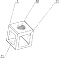
图2为本发明方形端子的结构示意图; Fig. 2 is the structural representation of square terminal of the present invention;
图3为本发明垫片的结构示意图; Fig. 3 is the structural representation of gasket of the present invention;
图4为本发明金属导体的结构示意图; Fig. 4 is the structural representation of metal conductor of the present invention;
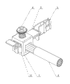
图5为本发明的使用状态示意图; Fig. 5 is a schematic diagram of the use state of the present invention;
图6为本发明的又一使用状态示意图。 Fig. 6 is a schematic diagram of another usage state of the present invention. the
具体实施方式 Detailed ways
参阅图1、图2、图3、图4,本发明包括方形端子1、垫片2、金属导体3及锁紧螺钉4,所述方形端子1为矩形体,其上水平设有“一”字形或“十”字形的通孔11、垂直设有与通孔11贯通的螺纹孔12,垫片2为矩形片,其至少一端头上设有凸起的卡扣21,金属导体3上至少设有一个卡槽31;所述垫片2叠放于金属导体3的上面,且卡扣21卡接于卡槽31内;垫片2连同金属导体3穿在方形端子1的通11内,锁紧螺钉4设于方形端子1的螺纹孔12内,且锁紧螺钉4的端头与垫片2的上表面触及。
Referring to Fig. 1, Fig. 2, Fig. 3 and Fig. 4, the present invention includes a
the
本发明是这样使用的: The present invention is used like this:
本发明包括方形端子1、垫片2、金属导体3及锁紧螺钉4,使用时,首先将垫片2叠放于金属导体3的上面,且使垫片2上的卡扣21卡接于金属导体3的卡槽31内,将方形端子1的通孔11套在金属导体3上装有垫片2的位置,然后将方形端子1连同金属导体3一起装入绝缘基座内,使方形端子1的通11对准绝缘基座内的电缆孔,将电缆5由电缆孔插入方形端子1的通孔11内,并使电缆5处于金属导体3与通孔11之间,拧紧锁紧螺钉4,锁紧螺钉4的端头压迫垫片2、金属导体3将电缆5与金属导体3挤压并紧固在方形端子1内,安装完成。拆卸时,只需松动锁紧螺钉4,电缆5与金属导体3即可分开。
The present invention includes a
由于本发明垫片2的设置,使锁紧螺钉4的端头不直接触及金属导体3和电缆,由于垫片2选用了不锈钢或其他硬度较高的金属材料,在垫片2的保护下,金属导体3由原先的点受力变成了面受力,防止了金属导体的局部变形和局部损伤,延长了金属导体3的使用寿命,达到多次反复使用的目的,保证了金属导体3与电缆5的连接可靠性。
Due to the setting of the
由于本发明垫片2的端头上至少设有一个凸起的卡扣21,使用时,垫片2叠放于金属导体3的上面,且使卡扣21卡接于卡槽31内,这样就保证在安装与连接电缆5的过程中,垫片2不会自行脱落,既方便施工,又能保证电缆5的连接的质量。
Since the end of the
本发明制造工艺简单,适宜标准化批量生产,尤其对造价较高的金属导体,可多次反复安装使用,具有施工方便,连接安全可靠,制造成本低、使用效果好的优点。 The invention has a simple manufacturing process and is suitable for standardized mass production, especially for metal conductors with high manufacturing costs, can be repeatedly installed and used, and has the advantages of convenient construction, safe and reliable connection, low manufacturing cost and good use effect.
参阅图5,本发明电缆5与金属导体3呈“T”字状连接的使用状态。
Referring to FIG. 5 , the
参阅图6,本发明电缆5与金属导体3呈“一”字状连接的使用状态。
Referring to Fig. 6, the
Claims (1)
Priority Applications (1)
| Application Number | Priority Date | Filing Date | Title |
|---|---|---|---|
| CN201210026839.3A CN102544828B (en) | 2012-02-08 | 2012-02-08 | Anti-extrusion connector wiring terminal |
Applications Claiming Priority (1)
| Application Number | Priority Date | Filing Date | Title |
|---|---|---|---|
| CN201210026839.3A CN102544828B (en) | 2012-02-08 | 2012-02-08 | Anti-extrusion connector wiring terminal |
Publications (2)
| Publication Number | Publication Date |
|---|---|
| CN102544828A true CN102544828A (en) | 2012-07-04 |
| CN102544828B CN102544828B (en) | 2014-04-30 |
Family
ID=46351128
Family Applications (1)
| Application Number | Title | Priority Date | Filing Date |
|---|---|---|---|
| CN201210026839.3A Expired - Fee Related CN102544828B (en) | 2012-02-08 | 2012-02-08 | Anti-extrusion connector wiring terminal |
Country Status (1)
| Country | Link |
|---|---|
| CN (1) | CN102544828B (en) |
Cited By (2)
| Publication number | Priority date | Publication date | Assignee | Title |
|---|---|---|---|---|
| CN103682939A (en) * | 2012-09-07 | 2014-03-26 | 佛山市国电电器有限公司 | Welding method for terminal of electric appliance and knitting strip |
| CN110790207A (en) * | 2019-11-20 | 2020-02-14 | 广东科谷实验室技术研究院(有限合伙) | A fixing device for a capping machine |
Citations (6)
| Publication number | Priority date | Publication date | Assignee | Title |
|---|---|---|---|---|
| CN1617389A (en) * | 2003-11-14 | 2005-05-18 | 施耐德电器工业公司 | Electrical terminal and electrical protection apparatus containing such a terminal |
| CN101170015A (en) * | 2006-10-28 | 2008-04-30 | Abb专利有限公司 | Appliance switchgear and connection terminals for appliance switchgear |
| CN101170016A (en) * | 2006-10-28 | 2008-04-30 | Abb专利有限公司 | Appliance switchgear and connection terminals for appliance switchgear |
| DE102008025428A1 (en) * | 2008-05-27 | 2009-12-03 | Phoenix Contact Gmbh & Co. Kg | Electrical connection device i.e. electrical connecting terminal, has conductor protection device comprising retaining section that is connected with upper wall sections of sheet bending part by flow-form connection |
| CN101641832A (en) * | 2007-03-18 | 2010-02-03 | 菲尼克斯电气公司 | Pe connection for a pin-and-socket connector |
| CN202268505U (en) * | 2011-04-25 | 2012-06-06 | 中山杰士美电子有限公司 | Wire clamping sheet |
-
2012
- 2012-02-08 CN CN201210026839.3A patent/CN102544828B/en not_active Expired - Fee Related
Patent Citations (6)
| Publication number | Priority date | Publication date | Assignee | Title |
|---|---|---|---|---|
| CN1617389A (en) * | 2003-11-14 | 2005-05-18 | 施耐德电器工业公司 | Electrical terminal and electrical protection apparatus containing such a terminal |
| CN101170015A (en) * | 2006-10-28 | 2008-04-30 | Abb专利有限公司 | Appliance switchgear and connection terminals for appliance switchgear |
| CN101170016A (en) * | 2006-10-28 | 2008-04-30 | Abb专利有限公司 | Appliance switchgear and connection terminals for appliance switchgear |
| CN101641832A (en) * | 2007-03-18 | 2010-02-03 | 菲尼克斯电气公司 | Pe connection for a pin-and-socket connector |
| DE102008025428A1 (en) * | 2008-05-27 | 2009-12-03 | Phoenix Contact Gmbh & Co. Kg | Electrical connection device i.e. electrical connecting terminal, has conductor protection device comprising retaining section that is connected with upper wall sections of sheet bending part by flow-form connection |
| CN202268505U (en) * | 2011-04-25 | 2012-06-06 | 中山杰士美电子有限公司 | Wire clamping sheet |
Cited By (2)
| Publication number | Priority date | Publication date | Assignee | Title |
|---|---|---|---|---|
| CN103682939A (en) * | 2012-09-07 | 2014-03-26 | 佛山市国电电器有限公司 | Welding method for terminal of electric appliance and knitting strip |
| CN110790207A (en) * | 2019-11-20 | 2020-02-14 | 广东科谷实验室技术研究院(有限合伙) | A fixing device for a capping machine |
Also Published As
| Publication number | Publication date |
|---|---|
| CN102544828B (en) | 2014-04-30 |
Similar Documents
| Publication | Publication Date | Title |
|---|---|---|
| CN209071162U (en) | A kind of clamping Wiring type safety contact switch | |
| CN204497398U (en) | A clamp-type LED terminal and its connector | |
| CN102544828B (en) | Anti-extrusion connector wiring terminal | |
| US9748676B2 (en) | Electrical connector | |
| CN206480806U (en) | A kind of high-power loose-proof socket | |
| CN205159579U (en) | Microspur type hermetic connector | |
| CN203150734U (en) | Wiring device of secondary circuit wiring head | |
| CN205543285U (en) | Split -type wiring terminal | |
| CN205692993U (en) | The electric snap joint of point measured by band | |
| CN216872786U (en) | A wire harness fixing device | |
| CN108232480B (en) | magnetic lead connecting device | |
| CN215377810U (en) | A dust-proof automobile wiring harness terminal structure | |
| CN202749554U (en) | Self-clamping socket | |
| CN209069983U (en) | A kind of testing terminal short-circuit tool | |
| CN203911180U (en) | Wiring terminal for electric power | |
| CN220492288U (en) | Multi-socket electric connector | |
| CN209592551U (en) | Battery wiring adapter | |
| CN107516776A (en) | Electric snap joint with measurement point | |
| CN201117886Y (en) | Surge protector socketing device | |
| CN114221150A (en) | A spring-based connector structure for high current transmission | |
| CN205562626U (en) | A New Type of Electric Meter with Connecting Terminals | |
| CN204304037U (en) | A kind of for conducting electricity the staggered flexible fingertip of plugging member | |
| CN219180791U (en) | a connector | |
| CN206602256U (en) | A kind of bridge type pluggable electric connector | |
| CN205376783U (en) | a terminal block |
Legal Events
| Date | Code | Title | Description |
|---|---|---|---|
| C06 | Publication | ||
| PB01 | Publication | ||
| C10 | Entry into substantive examination | ||
| SE01 | Entry into force of request for substantive examination | ||
| C14 | Grant of patent or utility model | ||
| GR01 | Patent grant | ||
| CF01 | Termination of patent right due to non-payment of annual fee | ||
| CF01 | Termination of patent right due to non-payment of annual fee |
Granted publication date: 20140430 |